EP1433667A2 - Seitenaufprallairbag - Google Patents
Seitenaufprallairbag Download PDFInfo
- Publication number
- EP1433667A2 EP1433667A2 EP03024429A EP03024429A EP1433667A2 EP 1433667 A2 EP1433667 A2 EP 1433667A2 EP 03024429 A EP03024429 A EP 03024429A EP 03024429 A EP03024429 A EP 03024429A EP 1433667 A2 EP1433667 A2 EP 1433667A2
- Authority
- EP
- European Patent Office
- Prior art keywords
- airbag
- gas
- chamber
- upper chamber
- lower chamber
- Prior art date
- Legal status (The legal status is an assumption and is not a legal conclusion. Google has not performed a legal analysis and makes no representation as to the accuracy of the status listed.)
- Withdrawn
Links
Images


Classifications
-
- B—PERFORMING OPERATIONS; TRANSPORTING
- B60—VEHICLES IN GENERAL
- B60R—VEHICLES, VEHICLE FITTINGS, OR VEHICLE PARTS, NOT OTHERWISE PROVIDED FOR
- B60R21/00—Arrangements or fittings on vehicles for protecting or preventing injuries to occupants or pedestrians in case of accidents or other traffic risks
- B60R21/02—Occupant safety arrangements or fittings, e.g. crash pads
- B60R21/16—Inflatable occupant restraints or confinements designed to inflate upon impact or impending impact, e.g. air bags
- B60R21/23—Inflatable members
- B60R21/231—Inflatable members characterised by their shape, construction or spatial configuration
- B60R21/233—Inflatable members characterised by their shape, construction or spatial configuration comprising a plurality of individual compartments; comprising two or more bag-like members, one within the other
-
- B—PERFORMING OPERATIONS; TRANSPORTING
- B60—VEHICLES IN GENERAL
- B60R—VEHICLES, VEHICLE FITTINGS, OR VEHICLE PARTS, NOT OTHERWISE PROVIDED FOR
- B60R21/00—Arrangements or fittings on vehicles for protecting or preventing injuries to occupants or pedestrians in case of accidents or other traffic risks
- B60R21/02—Occupant safety arrangements or fittings, e.g. crash pads
- B60R21/16—Inflatable occupant restraints or confinements designed to inflate upon impact or impending impact, e.g. air bags
- B60R21/20—Arrangements for storing inflatable members in their non-use or deflated condition; Arrangement or mounting of air bag modules or components
- B60R21/207—Arrangements for storing inflatable members in their non-use or deflated condition; Arrangement or mounting of air bag modules or components in vehicle seats
-
- B—PERFORMING OPERATIONS; TRANSPORTING
- B60—VEHICLES IN GENERAL
- B60R—VEHICLES, VEHICLE FITTINGS, OR VEHICLE PARTS, NOT OTHERWISE PROVIDED FOR
- B60R21/00—Arrangements or fittings on vehicles for protecting or preventing injuries to occupants or pedestrians in case of accidents or other traffic risks
- B60R21/02—Occupant safety arrangements or fittings, e.g. crash pads
- B60R21/16—Inflatable occupant restraints or confinements designed to inflate upon impact or impending impact, e.g. air bags
- B60R21/23—Inflatable members
- B60R21/231—Inflatable members characterised by their shape, construction or spatial configuration
- B60R21/23138—Inflatable members characterised by their shape, construction or spatial configuration specially adapted for side protection
-
- B—PERFORMING OPERATIONS; TRANSPORTING
- B60—VEHICLES IN GENERAL
- B60R—VEHICLES, VEHICLE FITTINGS, OR VEHICLE PARTS, NOT OTHERWISE PROVIDED FOR
- B60R21/00—Arrangements or fittings on vehicles for protecting or preventing injuries to occupants or pedestrians in case of accidents or other traffic risks
- B60R21/02—Occupant safety arrangements or fittings, e.g. crash pads
- B60R21/16—Inflatable occupant restraints or confinements designed to inflate upon impact or impending impact, e.g. air bags
- B60R21/23—Inflatable members
- B60R21/231—Inflatable members characterised by their shape, construction or spatial configuration
- B60R21/2334—Expansion control features
- B60R21/2338—Tethers
-
- B—PERFORMING OPERATIONS; TRANSPORTING
- B60—VEHICLES IN GENERAL
- B60R—VEHICLES, VEHICLE FITTINGS, OR VEHICLE PARTS, NOT OTHERWISE PROVIDED FOR
- B60R21/00—Arrangements or fittings on vehicles for protecting or preventing injuries to occupants or pedestrians in case of accidents or other traffic risks
- B60R21/02—Occupant safety arrangements or fittings, e.g. crash pads
- B60R21/16—Inflatable occupant restraints or confinements designed to inflate upon impact or impending impact, e.g. air bags
- B60R21/26—Inflatable occupant restraints or confinements designed to inflate upon impact or impending impact, e.g. air bags characterised by the inflation fluid source or means to control inflation fluid flow
- B60R21/261—Inflatable occupant restraints or confinements designed to inflate upon impact or impending impact, e.g. air bags characterised by the inflation fluid source or means to control inflation fluid flow with means other than bag structure to diffuse or guide inflation fluid
-
- B—PERFORMING OPERATIONS; TRANSPORTING
- B60—VEHICLES IN GENERAL
- B60R—VEHICLES, VEHICLE FITTINGS, OR VEHICLE PARTS, NOT OTHERWISE PROVIDED FOR
- B60R21/00—Arrangements or fittings on vehicles for protecting or preventing injuries to occupants or pedestrians in case of accidents or other traffic risks
- B60R21/02—Occupant safety arrangements or fittings, e.g. crash pads
- B60R21/16—Inflatable occupant restraints or confinements designed to inflate upon impact or impending impact, e.g. air bags
- B60R21/23—Inflatable members
- B60R21/231—Inflatable members characterised by their shape, construction or spatial configuration
- B60R21/233—Inflatable members characterised by their shape, construction or spatial configuration comprising a plurality of individual compartments; comprising two or more bag-like members, one within the other
- B60R2021/23316—Inner seams, e.g. creating separate compartments or used as tethering means
-
- B—PERFORMING OPERATIONS; TRANSPORTING
- B60—VEHICLES IN GENERAL
- B60R—VEHICLES, VEHICLE FITTINGS, OR VEHICLE PARTS, NOT OTHERWISE PROVIDED FOR
- B60R21/00—Arrangements or fittings on vehicles for protecting or preventing injuries to occupants or pedestrians in case of accidents or other traffic risks
- B60R21/02—Occupant safety arrangements or fittings, e.g. crash pads
- B60R21/16—Inflatable occupant restraints or confinements designed to inflate upon impact or impending impact, e.g. air bags
- B60R21/23—Inflatable members
- B60R21/231—Inflatable members characterised by their shape, construction or spatial configuration
- B60R21/233—Inflatable members characterised by their shape, construction or spatial configuration comprising a plurality of individual compartments; comprising two or more bag-like members, one within the other
- B60R2021/23324—Inner walls crating separate compartments, e.g. communicating with vents
-
- B—PERFORMING OPERATIONS; TRANSPORTING
- B60—VEHICLES IN GENERAL
- B60R—VEHICLES, VEHICLE FITTINGS, OR VEHICLE PARTS, NOT OTHERWISE PROVIDED FOR
- B60R21/00—Arrangements or fittings on vehicles for protecting or preventing injuries to occupants or pedestrians in case of accidents or other traffic risks
- B60R21/02—Occupant safety arrangements or fittings, e.g. crash pads
- B60R21/16—Inflatable occupant restraints or confinements designed to inflate upon impact or impending impact, e.g. air bags
- B60R21/23—Inflatable members
- B60R21/231—Inflatable members characterised by their shape, construction or spatial configuration
- B60R21/2334—Expansion control features
- B60R21/2338—Tethers
- B60R2021/23382—Internal tether means
Definitions
- the present invention relates to an airbag apparatus for side collision for protecting occupants in a vehicle in case of side collision and also in case of rollovers and the like and, more specifically, to an airbag apparatus for side collision having an airbag of which the interior is divided into a plurality of chambers.
- An airbag apparatus for side collision is, as is known, constructed in such a manner that an airbag is deployed on the side of an occupant by a gas generator, so that the body of the occupant is received by the deployed airbag.
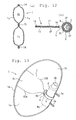
- Fig. 15 is a side view of a seat having an airbag apparatus for side collision in the same patent publication
- Fig. 16 is an enlarged cross-sectional view of the portion indicated by VI in Fig. 15.
- An airbag 18 is divided into an upper chamber 20 and a lower chamber 22 by a seam 24.
- the rear end of the seam 24 is located at some distance from the rear edge of the airbag 18, and a cylindrical tubular housing 30 is arranged at a gap between the rear end of the seam 24 and the rear edge of the airbag 18.
- a rod-shaped gas generator 36 is disposed in the tubular housing 30.
- the upper and the lower ends of the tubular housing 30 is provided with pipe clips 32, 34, and the gas generator 36 is fixed with the pipe clips 32, 34.
- the pipe clips 32, 34 seals between gas generator 36 and the tubular housing 30.
- the pipe clips 32, 34 are attached to mounting positions 26 on a seatback 14.
- the tubular housing 30 is formed with an outlet port 42 for the upper chamber for allowing gas to flow from the gas generator 36 into the upper chamber 20 and an outlet port 44 for the lower chamber for allowing gas to flow into the lower chamber 22.
- the opening area of the outlet port 44 for the lower chamber is larger than the opening area of the outlet port 42 for the upper chamber. Therefore, when the gas generator 36 is activated, the airbag 18 is inflated to achieve the internal pressure of about 0.5 bar for the upper chamber 20 and the internal pressure of about 1.5 bar for the lower chamber 22.
- the tubular housing 30 is used. Therefore, when the occupant is received by the lower chamber 22 of the deployed airbag 18, gas in the lower chamber 22 flows through the tubular housing 30 which forms communicating means between the lower chamber 22 and the upper chamber 20 into the upper chamber 20, and hence the gas pressure in the lower chamber cannot be maintained at a high level for a long time. Furthermore, because the rear end of the seam 24 and the rear edge of the gas distributor 30 have a slight space therebetween also forming communicating means between the lower chamber 22 and the upper chamber 20, gas leaks from the lower chamber 22 with the higher inner pressure to the upper chamber 20 with the lower inner pressure. This also lowers the gas pressure in the lower chamber 22 relatively quickly.
- An object of the present invention is to provide an airbag apparatus for side collision in which such problems are overcome and thus the gas pressure in a lower chamber is maintained at a high level for a sufficiently long time.
- An airbag apparatus for side collision includes an airbag including an occupant-side surface which faces an occupant when deployed, and a vehicle-body-side surface which is on the opposite side therefrom, and having an interior divided into a plurality of chambers including at least two chambers of an upper chamber and a lower chamber, a gas generator for deploying the airbag, and communicating means for communicating the upper chamber and the lower chamber, and is characterized in that gas flow preventing means, for example a check valve, for preventing gas from flowing from the lower chamber to the upper chamber are provided.
- gas flow preventing means for example a check valve
- the airbag apparatus for side collision since gas is prevented from flowing from the lower chamber to the upper chamber by the gas flow preventing means, the pressure in the lower chamber is maintained at a high level for a long time.
- the airbag apparatus for side collision can protect the occupant not only in the case of side collision, but also in the case of overturn.
- vent unit for allowing gas to flow out from the upper chamber toward the outside of the airbag.
- the present invention may also be such that the occupant-side surface and the vehicle-body-side surface are joined, the plurality of chambers are defined in the airbag by a linearly extending partitioning joint line, the communicating portion is formed in the airbag by part of the partitioning joint line being positioned away from one side edge of the airbag, and part of the gas flow preventing means are joined to the occupant-side surface and the vehicle-body-side surface by the partitioning joint line.
- mounting structure of the gas flow preventing means is simple and thus manufacturing thereof is easy.
- the airbag apparatus may further comprise a gas distributor enclosing the gas generator and including outlet ports for allowing gas from the gas generator at least to the upper chamber and the lower chamber, wherein the outlet port for the lower chamber of the gas distributor is larger than the outlet port for the upper chamber thereof.
- the airbag apparatus for side collision can protect the occupant not only in the case of side collision, but also in the case of overturn.
- the gas distributor may include a sheet for wrapping the gas generator, and the outlet port for the lower chamber of the gas distributor extends toward the lower chamber side with respect to the gas generator. Therefore, it is also possible that the extended portion is adapted to constitute the check valve.
- the check valve is constituted by the gas distributor, and thus a construction is simple and a manufacturing cost is low.
- the gas distributor in such a manner that the sheet is rolled in a cylindrical shape, the one edge and the other edge of the sheet are superimposed, and a mounting member of the gas generator is passed through the superimposed edges.
- the gas distributor can be constructed only by rolling the flat sheet into a cylindrical shape and passing the mounting member (for example a bolt) of the gas generator through the both edges, and thus manufacture of the gas distributor may be significantly simplified.
- a vent unit for allowing gas to flow from the upper chamber to the outside of the airbag is provided. An impact to the occupant crushing into the upper chamber is absorbed by gas flowing out from the upper chamber through the bent unit.
- the interior may be separated into a plurality of chambers by at least one separating mechanism;
- the gas generator may be cylindrical and disposed in the airbag; and the gas distributor may also be cylindrical and disposed in the airbag, the gas distributor holding the gas generator therein and having outlets for introducing gas to the upper chamber and the lower chamber from the gas generator.
- Such an airbag may have a hole in the vicinity of the gas distributor. The periphery of the hole is sealed by a sealing mechanism in an airtight manner. The sealing mechanism is connected with at least one of the separating mechanism.
- the gas flow preventing means comprise a clamp member extending through the hole which is wrapped around the gas distributor on the exterior of the airbag to press the airbag against the periphery of the gas distributor.
- the separating mechanism is connected with the sealing mechanism in the periphery of the hole, and the hole adjacent to the gas distributor is secured and pressed against the gas distributor by the clamp member.
- the airbag apparatus of the present invention may preferably include at least one inner chamber between the upper chamber and the lower chamber.
- gas may be directly supplied to the inner chamber from the gas distributor. This allows quicker inflation of the inner chamber of the airbag.
- the gas may flow into the inner chamber via the upper chamber such that when the occupant comes into contact with the upper chamber, the gas gradually flows into the inner chamber from the upper chamber so as to absorb the impact from the occupant.
- holes may preferably be provided along the gas distributor so that each of the holes is connected with the respective separating mechanism.
- a gas outlet for the inner chamber may be provided on the gas distributor between the separating mechanism.
- gas is directly supplied to the inner chamber from the gas distributor.
- a plurality of the separating mechanism is connected with a common hole, and the inner chamber is provided between the separating mechanism. In this case, gas is introduced to the inner chamber via, for example, the upper chamber. This structure is advantageous for having fewer holes.
- Fig. 1 is a perspective view of a seat of a vehicle provided with an airbag apparatus for side collision according to the present invention
- Fig. 2 (a) is a cross-sectional view of an embodiment taken along the line II-II in Fig. 1
- Figs. 2(b) and (c) are cross-sectional view taken along the line B-B and the line C-C in Fig. 2(a).
- Fig. 3 is a perspective view of a check valve.
- an airbag 1 is constructed to be deployed along the window side of a seat 10.
- the seat 10 is provided with a seat cushion 11, a seatback 12, and a headrest 13.
- a case (not shown) of an airbag apparatus for side collision is mounted to the side of the seatback 12, the airbag 1 is folded and stored in the case, and is covered with a module cover (not shown).
- the airbag 1 is formed into a bag shape by placing two sheet-shaped members such as cloth, resin sheet, or the like (cloth in this embodiment) one on top of another, and stitching the peripheral edges thereof together.
- the interior thereof is divided into a lower chamber 1a on the lower side and an upper chamber 1b on the upper side by a linear connected portion (seam in this embodiment) 2.
- the seam 2 connects the occupant-side surface 1p and the vehicle-body-side surface 1q on the opposite side therefrom of the airbag 1.
- the seam 2 is shaped substantially like a number 6 having a looped portion 2a.
- the rear end of the looped portion 2a of the seam 2 extends upward at some distance from the rear edge of the airbag 1, and a communicating portion communicating the upper chamber 1b and the lower chamber 1a is formed at the gap between the looped portion 2a and the rear edge of the airbag 1.
- the front edge of the seam 2 is continuing from the front edge of the airbag 1.
- a check valve 6c is disposed at this communicating portion and a rod-shaped gas generator 3 is disposed therein.
- the gas generator 3 is disposed so that the longitudinal direction is oriented in the vertical direction.
- the gas generator 3 is provided with gas injecting sections 3b at the upper and the lower ends, the gas injecting section may be provided only at one end.
- Two stud bolts 3a, 3a are projected from the gas generator 3.
- the stud bolts 3a, 3a are pierced through the check valve 6c and the rear edge of the airbag 1 and projects rearward from the airbag 1.
- the stud bolts 3a, 3a are secured to a case of the airbag apparatus for side collision with nuts. Accordingly the gas generator 3 and the airbag 1 are joined to the case.
- the check valve 6c is formed by placing two sheets 6a, 6a one on top of another, and stitching both sides with seams 6b. It is also possible to fold one sheet and stitch on one side.
- the side of the check valve 6c on the front side of the airbag is stitched (together) with the occupant-side surface 1p and the vehicle-body-side surface 1q by the looped portion 2a of the seam 2.
- the side of the check valve 6c on the rear side of the airbag is stitched to the occupant-side surface 1p and the vehicle-body-side surface 1q by a seam for stitching the occupant-side surface 1p and the vehicle-body-side surface 1q together along the peripheral edge of the airbag 1.
- the check valve 6c When the gas generator 3 is activated and gas is injected, the check valve 6c is inflated into a substantially cylindrical shape as shown in Fig. 3(b), and gas is allowed to pass through the check valve 6c.
- the outer peripheral surface of the check valve 6c is brought into intimate contact with the occupant-side surface 1p and the vehicle-body-side surface 1q, so that gas is prevented from passing between the outer surface of the check valve 6c with respect to the occupant-side surface 1p and the vehicle-body-side surface 1q.
- the outer surface of the check valve 6c may be joined with the occupant-side surface 1p and the vehicle-body-side surface 1q by adhesion or stitching.
- the upper chamber 1b is provided with a vent hole 5.
- the gas generator 3 when the vehicle encountered side collision or overturn, the gas generator 3 is activated and injects gas.
- the gas flows from the gas generator 3 to the lower chamber 1a and the upper chamber 1b respectively to deploy these chambers 1a and 1b. Accordingly, as shown in Fig. 1, the airbag 1 deploys along the window side of the seat 10.
- FIG. 4 is a cross-sectional view showing an airbag 1A provided with a substantially lateral U-shaped seam 2A in the airbag, and thus includes a middle chamber 1c between the upper chamber 1b and the lower chamber 1a.
- the front edge of the seam 2A is joined to the front edge of the airbag 1A.
- the seam 2A is provided with an open section 7 for communicating the upper chamber 1b and the middle chamber 1c.
- Other constructions of the airbag 1A are the same as the airbag 1 shown in Figs. 1 to 3, and thus the reference numerals identical to Figs. 1 to 3 represent the identical parts, in Fig 4.
- Fig. 5(a) is a cross sectional view of the further embodiment taken along the line II-II in Fig. 1;
- Fig. 5(b) and Fig. 6 are cross-sectional views taken along the line B-B, and the line III-III of Fig. 5(a), respectively.
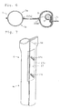
- Fig. 7 is a perspective view of a gas distributor;
- Fig. 8 is a perspective view of a gas generator and a holder thereof;
- Fig. 9 is a cross-sectional view taken along the line VI-VI in Fig. 5.
- the airbag 1 shown in Fig. 5 is formed into a bag shape by placing two sheet-shaped members such as cloth, resin sheet, or the like (cloth in this embodiment) one on top of another, and stitching the peripheral edges thereof together.
- the interior thereof is divided into a lower chamber 1a on the lower side and an upper chamber 1b on the upper side by a linear connected portion (seam in this embodiment) 2.
- the seam 2 connects an occupant-side surface 1p and a vehicle-body-side surface 1q on the opposite side therefrom of the airbag 1.
- the seam 2 is shaped substantially like a number 6 having a looped portion 2a.
- the rear end of the looped portion 2a of the seam 2 extends upward at some distance from the rear edge of the airbag 1, and a communicating portion communicating the upper chamber 1b and the lower chamber 1a is formed at the portion between the looped portion 2a and the rear edge of the airbag 1.
- the front edge of the seam 2 is continuing from the front edge of the airbag 1.
- a gas distributor 6 is disposed at this communicating portion and a rod-shaped gas generator 3 is disposed therein.
- the gas distributor 6 is formed by rolling a substantially square heat-resistant cloth into a cylindrical shape, superimposing one edge and the other edge thereof, and forming bolt insertion holes (or slits) at the superimposed portion. By inserting bolts 17c that will be described later into the bolt insertion hole, the cloth is maintained in a cylindrical shape.
- the cylindrical gas distributor 6 is disposed so that the axial direction of the cylinder is oriented in the vertical direction.
- the outlet port on the upper chamber side at the top of the gas distributor 6 is narrowed by a seam 6d.
- the outlet port of the lower chamber is larger than the outlet port of the upper chamber.
- the gas generator 3 is disposed so that the longitudinal direction is oriented in the vertical direction.
- the gas generator 3 is provided with a gas injecting section 3b at the lower end thereof.
- the gas generator 3 is held by an inflator holder (hereinafter referred to as a holder) 17.
- the holder 17 includes a main plate portion 17a in a plate shape and two band portions 17b in C-shape, and the bolts 17c are projected from the band portions 17b.
- the gas generator 3 is clamped between the main plate portion 17a and the band portions 17b.
- the bolts 17c are pierced through the main plate portion 17a and projects to the opposite side from the band portions 17b.
- the bolts 17c are, as described above, pierced through the bolt insertion holes formed on the both edges of the cloth constituting the gas distributor 6 and the rear edge of the airbag 1 and projected rearward from the airbag 1.
- the bolts 17c are secured to the case of the airbag apparatus for side collision with nuts. Accordingly, the gas generator 3 and the airbag 1 are connected to the case.
- the entire gas generator 3 is disposed in the gas distributor 6.
- the lower portion of the gas distributor 6 extends downward with respect to the lower end of the gas generator 3, and constitutes a check valve 6c.
- the gas distributor 6 When the gas generator 3 is activated and gas is injected, the gas distributor 6 is inflated into a substantially cylindrical shape as shown in Fig. 3(b), gas is distributed through the gas distributor 6 into the lower chamber 1a and the upper chamber 1b, and the airbag 1 is deployed.
- the outer peripheral surface of the gas distributor 6 is brought into intimate contact with the occupant-side surface 1p and the vehicle-body-side surface 1q, so that gas is prevented from passing between the outside the outer surface of the gas distributor 6 with respect to the occupant-side surface 1p and the vehicle-body-side surface 1q.
- the outer surface of the gas distributor 6 may be joined with the occupant-side surface 1p and the vehicle-body-side surface 1q by adhesion or stitching.
- the upper chamber 1b is provided with a vent hole 5.
- the gas generator 3 when the vehicle encountered side collision or overturn, the gas generator 3 is activated and injects gas.
- the gas flows from the gas generator 3 to the lower chamber 1a and the upper chamber 1b respectively to deploy these chambers 1a and 1b. Accordingly, as shown in Fig. 1, the airbag 1 deploys along the window side of the seat 10. Since the outlet port for the lower chamber of the gas distributor 6 is larger than the outlet port for the upper chamber thereof, and the gas injection port of the gas generator 3 is disposed at the lower portion of the gas distributor 6, the lower chamber 1a deploys earlier and to a higher internal pressure in comparison with the upper chamber 1b.
- Fig. 10 is a cross-sectional view showing an airbag 1A provided with a substantially lateral U-shaped seam 2A in the airbag, and thus includes a middle chamber 1c between the upper chamber 1b and the lower chamber 1a.
- the front edge of the seam 2A is joined to the front edge of the airbag 1A.
- the seam 2A is provided with an open section 7 for communicating the upper chamber 1b and the middle chamber 1c.
- Other constructions of the airbag 1A are the same as the aforementioned airbag 1 shown in Fig. 5 and 6, and thus the reference numerals identical to Fig. 5 and 6 represent the identical parts in Fig. 10.
- Fig. 11(a) is a perspective view of an automobile seat having a side airbag device according to a further embodiment.
- Fig. 11(b) is a lateral view of an airbag in Fig. 11(a).
- Fig. 12(a) is a sectional view taken along line IIa-IIa of Fig. 11(b).
- Fig. 12(b) is a sectional view taken along line IIb-IIb of Fig. 11(b).
- a side airbag 1 is inflated along the window side of a seat 10.
- the seat 10 includes a seat cushion 11, a seat back 12, and a head rest 13.
- a case (not shown in the drawings) for the side airbag device is provided on one side of the seat back 12.
- the side airbag 1 is folded and stored in the case and covered by a module cover (not shown in the drawings).
- the side airbag 1 includes a pair of sheet panels 1p and 1q formed of, for example, fabric or resin sheet. The peripheries of the sheet panels 1p and 1q are stitched together with a thread to form a seam 14. The interior of the side airbag 1 is separated into a lower chamber 1a and an upper chamber 1b by a seam 15 formed of a thread as a separating mechanism.
- a cylindrical gas distributor 4 is disposed along the rear inner edge of the side airbag 1 substantially in the vertical direction.
- the vertical direction is referred to as the cylindrical axis direction of the gas distributor 4.
- a cylindrical gas generator 3 is disposed in the gas distributor 4.
- the gas generator 3 is longitudinally disposed parallel to the cylindrical axis of the gas distributor 4.
- the lower end of the gas generator 3 is provided with a gas exhaust nozzle.
- Two stud bolts 3a protrude from the gas generator 3.
- the stud bolts 3a are pierced through the rear edges of the gas distributor 4 and the side airbag 1 to protrude from the back of the side airbag 1.
- the stud bolts 3a and 3a are fastened to the case (not shown in the drawings) of the side airbag device by a screw nut.
- the gas generator 3, the gas distributor 4 and the side airbag 1 are combined together with the case.
- a space 3S for gas passage is provided between the outer surface of the gas generator 3 and the inner surface of the gas distributor 4.
- a gas outlet 4a at the lower end of the cylindrical gas distributor 4 is disposed in the lower chamber 1a, and a gas outlet 4b at the upper end is disposed in the upper chamber 1b.
- the gas outlet 4a has a larger diameter than that of the gas outlet 4b. As shown in the drawing, the gas outlet 4a is pointed downwards while the gas outlet 4b is pointed upwards.
- a hole 8 which extends through the panels 1p and 1q is provided in the vicinity of the gas distributor 4 (towards the front of the side airbag 1 from the gas distributor 4).
- the panels 1p and 1q are stitched together in an airtight manner with a thread to form a seam 16.
- the seam 16 is connected with the seam 15.
- the seam 15 is connected with the seam 14 at the front edge of the side airbag 1.
- a clamp member 9, such as a band clamp, extends through the hole 6 to wrap around the gas distributor 4 on the exterior of the side airbag 1 so as to tightly secure the side airbag 1 to the gas distributor 4.
- the upper chamber 1b and the lower chamber 1a are completely separated from each other in an airtight manner in the periphery of the gas distributor 4.
- the side airbag device having the above structure, when a vehicle has a side-on collision or rolls over, gas is ejected from the gas generator 3.
- the gas is distributed from the gas outlets 4a and 4b of the gas distributor 4 to the lower chamber 1a and the upper chamber 1b, respectively, to inflate the chambers 1a and 1b.
- the airbag 1 is inflated along the window side of the seat 10.
- the lower gas outlet 4a has a larger diameter than that of the upper gas outlet 4b so as to supply a larger amount of gas and higher gas pressure to the lower chamber 1a than to the upper chamber 1b.
- the gas exhaust nozzle of the gas generator 3 is disposed at the lower part of the gas generator 3, a larger amount of gas as well as higher gas pressure is supplied to the lower chamber 1a.
- the lower chamber 1a is inflated at a higher inner pressure to keep the waist of a vehicle occupant from moving horizontally.
- the upper chamber 1b is inflated at a lower inner pressure than that of the lower chamber 1a to restrain the upper body of the occupant with softer impact.
- the gas pressure in the lower chamber 1a is maintained sufficiently high for a longer period of time since gas leakage from the lower chamber 1a to the upper chamber 1b is prevented. This is due to the seam 15 provided as the separating mechanism being connected with the seams 14 and 16, and the clamp member 9 being extended through the hole 8 to press the panels 1p and 1q of the side airbag 1 against the periphery of the gas distributor 4 in an airtight manner.
- gas is ejected from the gas distributor 4 in the vertical direction to rapidly inflate the side airbag 1 vertically.
- the side airbag 1 is then inflated in the forward direction.
- the side airbag 1 is separated into two chambers, that is, the upper chamber 1b and the lower chamber 1a.
- the side airbag 1 may alternatively be separated into three or more chambers.
- Fig. 13 and Fig. 14 illustrate embodiments each of which includes two seams 15A and 15B as the separating mechanism to provide an upper chamber 1b, a lower chamber 1a, and an inner chamber 1c.
- a side airbag 1 in Fig. 13 has one hole 8.
- the seams 15A and 15B are each connected with a seam 16 formed in the periphery of the hole 5.
- the seam 15B which separates the upper chamber 1b from the inner chamber 1c, is provided with a communicating portion 7 that links the two chambers 1b and 1c.
- Each of the seams 15A and 15B is connected with the seam 14 at the front edge of the side airbag 1A.
- the lower chamber 1a is separated from the inner chamber 1c and the upper chamber 1b in an airtight manner so that high gas pressure in the lower chamber 1a is maintained for a long period of time.
- a portion of the gas in the upper chamber 1b flows into the inner chamber 1c so as to absorb the impact from the occupant.
- two holes 8A and 8B are provided in different positions vertically along the gas distributor 4.
- a seam 16A in the periphery of the hole 8A is connected with the seam 15A.
- a seam 16B in the periphery of the hole 8B is connected with the seam 15B.
- the seams 15A and 15B are each connected with the seam 14 at the front edge of the side airbag 1B.
- the seam 15B is not provided with a communicating portion.
- a gas outlet 4c is provided between the holes 8A and 8B on the gas distributor 4 for distributing gas into the inner chamber 1c.
- the lower chamber 1a, the inner chamber 1c, and the upper chamber 1b are inflated.
- the lower chamber 1a is inflated the quickest of the three and is also inflated with the highest inner pressure.
- the lower chamber 1a is separated from the inner chamber 1c and the upper chamber 1b in an airtight manner so that high inner pressure in the lower chamber 1a is satisfactorily maintained for a long period of time.
- Gas is directly supplied to the inner chamber 1c from the gas distributor 4 and is ejected forward from the outlet 4c provided on the cylindrical surface of the gas distributor 4 so as to quickly inflate the inner chamber 1c in the forward direction.
- the present invention may have alternative embodiments not shown in the drawings.
- three or more separating seams may be provided to form four or more chambers.
- the present invention maintains higher pressure for a longer period of time in an inflated lower chamber separately formed in the lower part of an airbag.
Landscapes
- Engineering & Computer Science (AREA)
- Mechanical Engineering (AREA)
- Physics & Mathematics (AREA)
- Fluid Mechanics (AREA)
- Air Bags (AREA)
Applications Claiming Priority (6)
| Application Number | Priority Date | Filing Date | Title |
|---|---|---|---|
| JP2002380190A JP4062094B2 (ja) | 2002-12-27 | 2002-12-27 | エアバッグ装置 |
| JP2002380190 | 2002-12-27 | ||
| JP2003049537 | 2003-02-26 | ||
| JP2003049537A JP4103628B2 (ja) | 2003-02-26 | 2003-02-26 | 側突用エアバッグ装置 |
| JP2003060107 | 2003-03-06 | ||
| JP2003060107A JP4103633B2 (ja) | 2003-03-06 | 2003-03-06 | 側突用エアバッグ装置 |
Publications (2)
| Publication Number | Publication Date |
|---|---|
| EP1433667A2 true EP1433667A2 (de) | 2004-06-30 |
| EP1433667A3 EP1433667A3 (de) | 2004-09-22 |
Family
ID=32475242
Family Applications (1)
| Application Number | Title | Priority Date | Filing Date |
|---|---|---|---|
| EP03024429A Withdrawn EP1433667A3 (de) | 2002-12-27 | 2003-10-23 | Seitenaufprallairbag |
Country Status (3)
| Country | Link |
|---|---|
| US (1) | US7168733B2 (de) |
| EP (1) | EP1433667A3 (de) |
| CN (1) | CN1329228C (de) |
Cited By (19)
| Publication number | Priority date | Publication date | Assignee | Title |
|---|---|---|---|---|
| WO2005028264A1 (en) * | 2003-09-25 | 2005-03-31 | Autoliv Development Ab | Improvements in or relating to a gas deflector |
| EP1559620A1 (de) * | 2004-01-28 | 2005-08-03 | Nihon Plast Co., Ltd. | Airbagsystem |
| US7267363B2 (en) | 2003-04-02 | 2007-09-11 | Autoliv Development Ab | Air-bag unit mounted on a seat |
| DE102006023271A1 (de) * | 2006-05-18 | 2007-11-22 | Autoliv Development Ab | Gassack-Einheit |
| US7322595B2 (en) | 2002-06-07 | 2008-01-29 | Autoliv Development Ab | Electrically insulated fixing device for an airbag module |
| US7357411B2 (en) | 2004-11-16 | 2008-04-15 | Takata Corporation | Airbag apparatus |
| DE102006049429A1 (de) * | 2006-10-16 | 2008-04-17 | Autoliv Development Ab | Airbageinrichtung |
| DE102007003863A1 (de) | 2007-01-25 | 2008-08-07 | Autoliv Development Ab | Seitengassackanordnung |
| US7422234B2 (en) | 2003-05-10 | 2008-09-09 | Autoliv Development Ab | Air-bag assembly for a motor vehicle |
| EP1839963A3 (de) * | 2006-03-31 | 2009-07-01 | Ford Global Technologies, LLC | Airbag für ein Kraftfahrzeug |
| US7594678B2 (en) | 2003-11-11 | 2009-09-29 | Autoliv Development Ab | Side air-bag with internal tether |
| US7669887B2 (en) | 2003-06-20 | 2010-03-02 | Autoliv Development Ab | Air bag |
| DE102010051793A1 (de) * | 2010-11-18 | 2012-05-24 | GM Global Technology Operations LLC | Kraftfahrzeug mit Seitenairbag |
| EP2397376A4 (de) * | 2009-02-13 | 2012-07-25 | Ashimori Ind Co Ltd | Airbag |
| US8246076B2 (en) | 2008-12-18 | 2012-08-21 | Takata AG | Airbag for a vehicle occupant restraint system and a method for protecting a vehicle occupant |
| EP2463159A4 (de) * | 2009-08-03 | 2012-12-26 | Toyota Motor Co Ltd | Seitenairbagvorrichtung für ein fahrzeug |
| US8931801B2 (en) | 2009-04-28 | 2015-01-13 | Takata AG | Airbag for a vehicle occupant restraint system and method for producing a vehicle occupant restraint system |
| DE102009057420B4 (de) * | 2008-12-09 | 2016-06-02 | Toyoda Gosei Co., Ltd. | Airbagvorrichtung |
| EP3400152A4 (de) * | 2016-03-16 | 2019-07-24 | Autoliv ASP, Inc. | Seitenairbag mit innendiffusor |
Families Citing this family (62)
| Publication number | Priority date | Publication date | Assignee | Title |
|---|---|---|---|---|
| US7338069B2 (en) * | 2004-04-02 | 2008-03-04 | Automotive Technologies International, Inc. | Airbags with internal valves |
| US20050104342A1 (en) * | 2003-11-17 | 2005-05-19 | Ford Global Technologies, Llc | An improved side airbag |
| DE10360468A1 (de) * | 2003-12-22 | 2005-08-04 | Trw Occupant Restraint Systems Gmbh & Co. Kg | Gassackmodul |
| US7316415B2 (en) * | 2004-08-30 | 2008-01-08 | Autoliv Asp, Inc. | Dual chamber airbag |
| JP4297014B2 (ja) * | 2004-09-08 | 2009-07-15 | 豊田合成株式会社 | エアバッグ装置 |
| JP4846595B2 (ja) * | 2004-11-04 | 2011-12-28 | オートリブ ディベロップメント エービー | 車両用サイドエアバッグ装置 |
| CN101767568B (zh) * | 2004-11-12 | 2013-01-23 | 高田-彼得里公开股份有限公司 | 气囊装置 |
| JP4775111B2 (ja) * | 2005-05-25 | 2011-09-21 | タカタ株式会社 | 乗員保護装置 |
| CN100441448C (zh) * | 2005-05-31 | 2008-12-10 | 丰田合成株式会社 | 用于保护乘员的方法与结构 |
| WO2006132990A1 (en) * | 2005-06-03 | 2006-12-14 | Abc Group, Inc. | Active bolster |
| US7980589B2 (en) * | 2005-11-17 | 2011-07-19 | Salflex Polymers Ltd. | Inflatable bolster |
| WO2007056849A1 (en) * | 2005-11-17 | 2007-05-24 | Salflex Polymers Ltd. | Bolster deployment pattern |
| JP4898826B2 (ja) * | 2005-12-01 | 2012-03-21 | タカタ・ペトリ アーゲー | エアバッグ装置 |
| JP5007047B2 (ja) * | 2006-01-13 | 2012-08-22 | 本田技研工業株式会社 | エアバッグ装置 |
| JP2007210420A (ja) * | 2006-02-08 | 2007-08-23 | Takata Corp | エアベルト及びエアベルト装置 |
| DE102006013287A1 (de) * | 2006-03-23 | 2007-09-27 | Daimlerchrysler Ag | Gassack für ein Kraftfahrzeug |
| JP2007276522A (ja) * | 2006-04-03 | 2007-10-25 | Toyoda Gosei Co Ltd | サイドエアバッグ装置 |
| JP5120599B2 (ja) * | 2006-06-20 | 2013-01-16 | マツダ株式会社 | サイドエアバッグ装置 |
| DE202006010878U1 (de) * | 2006-07-11 | 2006-09-21 | Takata-Petri Ag | Gassackanordnung für ein Fahrzeuginsassen-Rückhaltesystem |
| JP4245031B2 (ja) * | 2006-09-28 | 2009-03-25 | トヨタ自動車株式会社 | 車両用サイドエアバッグ装置 |
| US7278656B1 (en) | 2007-01-30 | 2007-10-09 | Key Safety Systems, Inc. | Seat mounted side impact airbag module |
| JP2008189132A (ja) * | 2007-02-05 | 2008-08-21 | Toyoda Gosei Co Ltd | サイドエアバッグ装置 |
| US7770921B2 (en) * | 2007-05-25 | 2010-08-10 | Autoliv Development Ab | Airbag for protection of a vehicle occupant |
| US20080252054A1 (en) * | 2007-04-16 | 2008-10-16 | Hyundai Mobis Co., Ltd. | Air bag cushion |
| EP2019001B1 (de) * | 2007-07-27 | 2012-06-13 | Dalphi Metal España, S.A. | Doppelkammerairbagmodul mit Anti-Rücklauf-Diffusor |
| JP5125596B2 (ja) * | 2008-02-22 | 2013-01-23 | 豊田合成株式会社 | 側突用エアバッグ装置 |
| JP5070084B2 (ja) * | 2008-02-22 | 2012-11-07 | タカタ株式会社 | 側突用エアバッグ装置 |
| JP5472294B2 (ja) | 2009-05-11 | 2014-04-16 | トヨタ自動車株式会社 | 車両用サイドエアバッグ装置 |
| DE102009023923B4 (de) * | 2009-06-04 | 2016-02-11 | Autoliv Development Ab | Befestigungsklemme und Gassack-Einheit |
| US20110012328A1 (en) * | 2009-07-17 | 2011-01-20 | Ford Global Technologies, Llc | Side curtain airbag with pressure control device |
| US8596678B2 (en) * | 2009-10-05 | 2013-12-03 | Autoliv Asp, Inc. | Air bag with pressure-managed gas delivery inflatable duct |
| JP5403070B2 (ja) | 2009-12-21 | 2014-01-29 | トヨタ自動車株式会社 | サイドエアバッグ装置及びサイドエアバッグの縫製方法 |
| US8459689B2 (en) | 2009-12-24 | 2013-06-11 | Salflex Polymers Ltd. | Passenger side active knee bolster |
| CN102869548B (zh) * | 2010-04-23 | 2015-10-14 | 丰田自动车株式会社 | 车辆用侧面安全气囊装置 |
| WO2011137517A1 (en) | 2010-05-05 | 2011-11-10 | Salflex Polymers Ltd. | Injection molded inflatable active bolster |
| US8579325B2 (en) | 2010-11-09 | 2013-11-12 | Salflex Polymers Ltd. | Active bolster |
| US9254808B2 (en) | 2011-02-07 | 2016-02-09 | Salflex Polymers Limited | Active bolster assembly |
| DE112012004364T5 (de) | 2011-10-21 | 2014-07-03 | Tk Holdings Inc. | Airbag-Modul und Verfahren zur Steuerung von Gas darin |
| KR101360434B1 (ko) * | 2012-03-28 | 2014-02-11 | 기아자동차주식회사 | 사이드 에어백 |
| JP5787097B2 (ja) * | 2012-07-06 | 2015-09-30 | 豊田合成株式会社 | エアバッグ装置 |
| US8622423B1 (en) * | 2012-09-11 | 2014-01-07 | Key Safety Systems, Inc. | Airbag with heat shield |
| JP2014184805A (ja) * | 2013-03-22 | 2014-10-02 | Toyota Motor Corp | 自動車用サイドエアバッグ装置 |
| JP2014184852A (ja) * | 2013-03-22 | 2014-10-02 | Toyota Motor Corp | 車両用サイドエアバッグ装置 |
| JP5949712B2 (ja) * | 2013-09-18 | 2016-07-13 | トヨタ自動車株式会社 | 車両用サイドエアバッグ装置及び車両用シート |
| US9108587B2 (en) * | 2013-10-08 | 2015-08-18 | Autoliv Asp, Inc. | 3-layer “C” shaped side airbag |
| US9150186B1 (en) | 2014-03-13 | 2015-10-06 | Ford Global Technologies, Llc | Passenger airbag with secondary chamber |
| US9340176B2 (en) | 2014-03-13 | 2016-05-17 | Ford Global Technologies, Llc | Passenger airbag with secondary chamber |
| JP6197777B2 (ja) * | 2014-10-10 | 2017-09-20 | トヨタ自動車株式会社 | 車両用ファーサイドエアバッグ装置 |
| US9592788B2 (en) * | 2015-01-14 | 2017-03-14 | GM Global Technology Operations LLC | Front center airbag lower chamber and panel |
| JP6583145B2 (ja) * | 2016-06-03 | 2019-10-02 | 豊田合成株式会社 | エアバッグ装置 |
| JP6454364B2 (ja) * | 2017-01-23 | 2019-01-16 | 本田技研工業株式会社 | エアバッグ装置 |
| DE102018103071B4 (de) * | 2017-11-15 | 2024-03-07 | Joyson Safety Systems Germany Gmbh | Gassack für ein Fahrzeuginsassen-Rückhaltesystem eines Kraftfahrzeugs |
| US10703321B2 (en) * | 2017-11-20 | 2020-07-07 | Ford Global Technologies, Llc | Airbag assembly |
| KR102206666B1 (ko) * | 2018-01-15 | 2021-01-22 | 오토리브 디벨로프먼트 에이비 | 사이드 에어백 장치 및 이것을 구비한 차량용 시트 |
| US10766448B2 (en) | 2018-06-01 | 2020-09-08 | Autoliv Asp, Inc. | Side airbag assembly |
| DE102018130029A1 (de) * | 2018-11-28 | 2020-05-28 | Dr. Ing. H.C. F. Porsche Aktiengesellschaft | Luftsackvorrichtung für einen Seitenairbag eines Fahrzeugs |
| US11007971B2 (en) * | 2019-02-15 | 2021-05-18 | Ford Global Technologies, Llc | Side airbag including spacer chamber |
| US10843654B2 (en) * | 2019-04-26 | 2020-11-24 | Autoliv Asp, Inc. | Side airbag assembly |
| US10988100B2 (en) | 2019-08-29 | 2021-04-27 | Ford Global Technologies, Llc | Side airbag including non-expandable region |
| US11479201B2 (en) * | 2020-02-20 | 2022-10-25 | Schroth Safety Products Llc | Chamber adjustable stiffness airbag |
| CN111891065A (zh) * | 2020-07-28 | 2020-11-06 | 宁波吉利汽车研究开发有限公司 | 一种安全气囊的实现方法、控制方法及安全气囊和汽车 |
| JP2024061008A (ja) * | 2022-10-20 | 2024-05-07 | 株式会社Subaru | エアバッグ装置 |
Family Cites Families (34)
| Publication number | Priority date | Publication date | Assignee | Title |
|---|---|---|---|---|
| US3642303A (en) * | 1970-02-13 | 1972-02-15 | Gen Motors Corp | Vehicle occupant restraint system |
| US3768830A (en) * | 1970-09-23 | 1973-10-30 | Eaton Corp | Vehicle knee bag |
| US4262931A (en) * | 1979-09-18 | 1981-04-21 | Ford Motor Company | Air bag restraint system |
| JPH0420857A (ja) | 1990-05-15 | 1992-01-24 | Oouchi Shinko Kagaku Kogyo Kk | ゴム表面移行物の分折方法 |
| US5161821A (en) * | 1991-09-13 | 1992-11-10 | Davidson Textron Inc. | Side impact airbag system attached to seat belt |
| US5273309A (en) * | 1992-06-19 | 1993-12-28 | General Motors Corporation | Air bag for side impact |
| US5556128A (en) * | 1994-11-24 | 1996-09-17 | Volkswagen Ag | Safety arrangement for a vehicle occupant |
| DE19522765A1 (de) * | 1995-06-27 | 1997-01-02 | Pars Passive Rueckhaltesysteme | Airbagmodul |
| DE19538657A1 (de) * | 1995-10-17 | 1997-04-24 | Trw Repa Gmbh | Gassack-Seitenaufprall-Schutzeinrichtung |
| DE29517372U1 (de) * | 1995-11-02 | 1996-02-01 | Trw Repa Gmbh | Gassack-Seitenaufprall-Schutzeinrichtung |
| US5718450A (en) * | 1996-01-19 | 1998-02-17 | Takata, Inc. | Inflatable restraint system having a head/thorax cushion for side impact protection |
| US5632506A (en) * | 1996-06-14 | 1997-05-27 | Trw Vehicle Safety Systems Inc. | Vehicle occupant protection apparatus |
| JP3430835B2 (ja) * | 1996-09-26 | 2003-07-28 | 三菱自動車工業株式会社 | エアバック装置 |
| JPH10100827A (ja) | 1996-09-26 | 1998-04-21 | Mitsubishi Motors Corp | エアバッグ装置 |
| JP3381536B2 (ja) | 1996-11-18 | 2003-03-04 | 豊田合成株式会社 | 側部用エアバッグ装置 |
| JPH10181752A (ja) | 1996-12-25 | 1998-07-07 | Tetsuya Ogino | エアバッグ |
| JPH10217896A (ja) | 1997-02-07 | 1998-08-18 | Toyota Motor Corp | サイドエアバッグ装置 |
| US5845935A (en) * | 1997-03-07 | 1998-12-08 | Morton International, Inc. | Side airbag module |
| JP3758287B2 (ja) | 1997-03-31 | 2006-03-22 | 日産自動車株式会社 | エアバッグ装置 |
| US5775729A (en) * | 1997-05-06 | 1998-07-07 | Autoliv Asp, Inc. | Integral head/torso airbag and knee airbag restraint system |
| JP2933894B2 (ja) | 1997-07-08 | 1999-08-16 | マツダ株式会社 | 車体側部のエネルギ吸収構造 |
| JPH11157407A (ja) | 1997-11-28 | 1999-06-15 | Nippon Plast Co Ltd | エアバッグ |
| JPH11157406A (ja) | 1997-11-28 | 1999-06-15 | Nippon Plast Co Ltd | エアバッグ |
| US5957493A (en) * | 1997-12-19 | 1999-09-28 | Autoliv Asp, Inc. | Airbag check valve |
| JPH11321535A (ja) * | 1998-05-12 | 1999-11-24 | Toyoda Gosei Co Ltd | サイドエアバッグ装置のエアバッグ |
| DE19850448B4 (de) | 1998-11-02 | 2014-08-21 | TAKATA Aktiengesellschaft | Airbag-Anordnung |
| DE29822159U1 (de) * | 1998-12-11 | 1999-05-12 | Trw Repa Gmbh | Gassack-Seitenaufprall-Schutzeinrichtung |
| JP3755340B2 (ja) | 1999-05-27 | 2006-03-15 | タカタ株式会社 | 自動車乗員頭部の保護バッグ及び保護装置 |
| DE19930155A1 (de) * | 1999-06-30 | 2001-01-04 | Takata Europ Gmbh | Rückschlagventil für eine Luftsack |
| DE19930157B4 (de) | 1999-06-30 | 2012-10-31 | TAKATA Aktiengesellschaft | Luftsack für ein Kraftfahrzeug |
| DE29921743U1 (de) * | 1999-12-10 | 2000-04-13 | Trw Repa Gmbh | Fahrzeuginsassen-Rückhaltesystem |
| JP3915544B2 (ja) | 2002-02-25 | 2007-05-16 | タカタ株式会社 | エアバッグ装置 |
| JP4285167B2 (ja) * | 2003-01-30 | 2009-06-24 | タカタ株式会社 | 側突用エアバッグ装置 |
| JP4285633B2 (ja) | 2003-01-31 | 2009-06-24 | 芦森工業株式会社 | エアバッグ装置 |
-
2003
- 2003-09-23 US US10/667,463 patent/US7168733B2/en not_active Expired - Lifetime
- 2003-09-29 CN CNB031327028A patent/CN1329228C/zh not_active Expired - Fee Related
- 2003-10-23 EP EP03024429A patent/EP1433667A3/de not_active Withdrawn
Cited By (25)
| Publication number | Priority date | Publication date | Assignee | Title |
|---|---|---|---|---|
| US7322595B2 (en) | 2002-06-07 | 2008-01-29 | Autoliv Development Ab | Electrically insulated fixing device for an airbag module |
| US7267363B2 (en) | 2003-04-02 | 2007-09-11 | Autoliv Development Ab | Air-bag unit mounted on a seat |
| US7422234B2 (en) | 2003-05-10 | 2008-09-09 | Autoliv Development Ab | Air-bag assembly for a motor vehicle |
| US7669887B2 (en) | 2003-06-20 | 2010-03-02 | Autoliv Development Ab | Air bag |
| US7644950B2 (en) | 2003-09-25 | 2010-01-12 | Autoliv Development Ab | Gas deflector for an air-bag |
| WO2005028264A1 (en) * | 2003-09-25 | 2005-03-31 | Autoliv Development Ab | Improvements in or relating to a gas deflector |
| US7594678B2 (en) | 2003-11-11 | 2009-09-29 | Autoliv Development Ab | Side air-bag with internal tether |
| EP1559620A1 (de) * | 2004-01-28 | 2005-08-03 | Nihon Plast Co., Ltd. | Airbagsystem |
| US7384062B2 (en) | 2004-01-28 | 2008-06-10 | Nihon Plast Co., Ltd. | Airbag system |
| US7357411B2 (en) | 2004-11-16 | 2008-04-15 | Takata Corporation | Airbag apparatus |
| EP1839963A3 (de) * | 2006-03-31 | 2009-07-01 | Ford Global Technologies, LLC | Airbag für ein Kraftfahrzeug |
| WO2007134729A1 (de) * | 2006-05-18 | 2007-11-29 | Autoliv Development Ab | Gassack-einheit |
| DE102006023271A1 (de) * | 2006-05-18 | 2007-11-22 | Autoliv Development Ab | Gassack-Einheit |
| DE102006049429B4 (de) * | 2006-10-16 | 2015-12-31 | Autoliv Development Ab | Airbageinrichtung |
| DE102006049429A1 (de) * | 2006-10-16 | 2008-04-17 | Autoliv Development Ab | Airbageinrichtung |
| DE102007003863B4 (de) * | 2007-01-25 | 2010-03-11 | Autoliv Development Ab | Seitengassackanordnung |
| DE102007003863A1 (de) | 2007-01-25 | 2008-08-07 | Autoliv Development Ab | Seitengassackanordnung |
| DE102009057420B4 (de) * | 2008-12-09 | 2016-06-02 | Toyoda Gosei Co., Ltd. | Airbagvorrichtung |
| US8246076B2 (en) | 2008-12-18 | 2012-08-21 | Takata AG | Airbag for a vehicle occupant restraint system and a method for protecting a vehicle occupant |
| EP2397376A4 (de) * | 2009-02-13 | 2012-07-25 | Ashimori Ind Co Ltd | Airbag |
| US8528934B2 (en) | 2009-02-13 | 2013-09-10 | Ashimori Industry Co., Ltd. | Airbag device |
| US8931801B2 (en) | 2009-04-28 | 2015-01-13 | Takata AG | Airbag for a vehicle occupant restraint system and method for producing a vehicle occupant restraint system |
| EP2463159A4 (de) * | 2009-08-03 | 2012-12-26 | Toyota Motor Co Ltd | Seitenairbagvorrichtung für ein fahrzeug |
| DE102010051793A1 (de) * | 2010-11-18 | 2012-05-24 | GM Global Technology Operations LLC | Kraftfahrzeug mit Seitenairbag |
| EP3400152A4 (de) * | 2016-03-16 | 2019-07-24 | Autoliv ASP, Inc. | Seitenairbag mit innendiffusor |
Also Published As
| Publication number | Publication date |
|---|---|
| US20050189742A1 (en) | 2005-09-01 |
| EP1433667A3 (de) | 2004-09-22 |
| US7168733B2 (en) | 2007-01-30 |
| CN1329228C (zh) | 2007-08-01 |
| CN1511738A (zh) | 2004-07-14 |
Similar Documents
| Publication | Publication Date | Title |
|---|---|---|
| EP1433667A2 (de) | Seitenaufprallairbag | |
| US8562015B2 (en) | Vehicle side airbag device | |
| US7607690B2 (en) | Airbag and airbag apparatus | |
| US7597351B2 (en) | Side airbag apparatus, motor vehicle seat, and gas distributor of inflator | |
| US8628111B2 (en) | Side airbag device | |
| CN101842269B (zh) | 气囊模块 | |
| EP2042387B1 (de) | Airbag zum Knieschutz | |
| CN102414054B (zh) | 安全气囊装置 | |
| US8727376B2 (en) | Airbag apparatus | |
| EP1364839A2 (de) | Verbesserte Seitenluftsackeinrichtung | |
| JP2004243976A (ja) | 側突用エアバッグ装置 | |
| US20060197320A1 (en) | Airbag and airbag apparatus | |
| US7780191B2 (en) | Side airbag apparatus | |
| JP2005041457A (ja) | 側突用エアバッグ装置 | |
| KR20060130696A (ko) | 측면 충돌 억제 모듈 | |
| US7080853B2 (en) | Airbag for head-protecting airbag device | |
| JP3718763B2 (ja) | 頭部保護エアバッグ装置 | |
| JP4103633B2 (ja) | 側突用エアバッグ装置 | |
| JP2009537368A5 (de) | ||
| JP4062094B2 (ja) | エアバッグ装置 | |
| JP4103586B2 (ja) | エアバッグ装置 | |
| JP5465019B2 (ja) | カーテンエアバッグ装置 | |
| JP2004256017A (ja) | 側突用エアバッグ装置 | |
| US7614649B2 (en) | Airbag system | |
| JP5120354B2 (ja) | エアバッグ装置 |
Legal Events
| Date | Code | Title | Description |
|---|---|---|---|
| PUAI | Public reference made under article 153(3) epc to a published international application that has entered the european phase |
Free format text: ORIGINAL CODE: 0009012 |
|
| AK | Designated contracting states |
Kind code of ref document: A2 Designated state(s): AT BE BG CH CY CZ DE DK EE ES FI FR GB GR HU IE IT LI LU MC NL PT RO SE SI SK TR |
|
| AX | Request for extension of the european patent |
Extension state: AL LT LV MK |
|
| PUAL | Search report despatched |
Free format text: ORIGINAL CODE: 0009013 |
|
| RIC1 | Information provided on ipc code assigned before grant |
Ipc: 7B 60R 21/26 B Ipc: 7B 60R 21/16 A |
|
| AK | Designated contracting states |
Kind code of ref document: A3 Designated state(s): AT BE BG CH CY CZ DE DK EE ES FI FR GB GR HU IE IT LI LU MC NL PT RO SE SI SK TR |
|
| AX | Request for extension of the european patent |
Extension state: AL LT LV MK |
|
| 17P | Request for examination filed |
Effective date: 20050321 |
|
| AKX | Designation fees paid |
Designated state(s): DE FR GB SE |
|
| 17Q | First examination report despatched |
Effective date: 20090811 |
|
| STAA | Information on the status of an ep patent application or granted ep patent |
Free format text: STATUS: THE APPLICATION IS DEEMED TO BE WITHDRAWN |
|
| 18D | Application deemed to be withdrawn |
Effective date: 20140429 |