EP1433733A2 - Fexibles Speicherfördersystem zum Anordnen von gesammelten Dokumenten - Google Patents
Fexibles Speicherfördersystem zum Anordnen von gesammelten Dokumenten Download PDFInfo
- Publication number
- EP1433733A2 EP1433733A2 EP03029666A EP03029666A EP1433733A2 EP 1433733 A2 EP1433733 A2 EP 1433733A2 EP 03029666 A EP03029666 A EP 03029666A EP 03029666 A EP03029666 A EP 03029666A EP 1433733 A2 EP1433733 A2 EP 1433733A2
- Authority
- EP
- European Patent Office
- Prior art keywords
- roller
- documents
- nips
- nip
- downstream
- Prior art date
- Legal status (The legal status is an assumption and is not a legal conclusion. Google has not performed a legal analysis and makes no representation as to the accuracy of the status listed.)
- Withdrawn
Links
- 230000035508 accumulation Effects 0.000 claims abstract description 97
- 238000009825 accumulation Methods 0.000 claims abstract description 97
- 238000005070 sampling Methods 0.000 claims abstract description 27
- 230000001360 synchronised effect Effects 0.000 claims abstract description 26
- 238000012546 transfer Methods 0.000 claims abstract description 15
- 238000004891 communication Methods 0.000 claims abstract description 6
- 238000006073 displacement reaction Methods 0.000 claims description 26
- 238000000034 method Methods 0.000 claims description 16
- 230000001133 acceleration Effects 0.000 claims description 13
- 238000011144 upstream manufacturing Methods 0.000 claims description 10
- 230000000737 periodic effect Effects 0.000 claims description 6
- 238000011143 downstream manufacturing Methods 0.000 claims description 5
- 238000004519 manufacturing process Methods 0.000 claims description 3
- 230000003287 optical effect Effects 0.000 claims description 3
- 230000032258 transport Effects 0.000 description 55
- 238000004364 calculation method Methods 0.000 description 4
- 230000007246 mechanism Effects 0.000 description 3
- 230000008569 process Effects 0.000 description 3
- 238000012545 processing Methods 0.000 description 3
- 238000003780 insertion Methods 0.000 description 2
- 230000037431 insertion Effects 0.000 description 2
- 238000013459 approach Methods 0.000 description 1
- 230000008901 benefit Effects 0.000 description 1
- 230000003247 decreasing effect Effects 0.000 description 1
- 230000001419 dependent effect Effects 0.000 description 1
- 238000001514 detection method Methods 0.000 description 1
- 238000010586 diagram Methods 0.000 description 1
- 238000009434 installation Methods 0.000 description 1
- 239000013641 positive control Substances 0.000 description 1
- 238000002360 preparation method Methods 0.000 description 1
- 239000002994 raw material Substances 0.000 description 1
- 238000007789 sealing Methods 0.000 description 1
- 238000000926 separation method Methods 0.000 description 1
- 239000013589 supplement Substances 0.000 description 1
- 238000005303 weighing Methods 0.000 description 1
Images
Classifications
-
- B—PERFORMING OPERATIONS; TRANSPORTING
- B65—CONVEYING; PACKING; STORING; HANDLING THIN OR FILAMENTARY MATERIAL
- B65H—HANDLING THIN OR FILAMENTARY MATERIAL, e.g. SHEETS, WEBS, CABLES
- B65H9/00—Registering, e.g. orientating, articles; Devices therefor
- B65H9/004—Deskewing sheet by abutting against a stop, i.e. producing a buckling of the sheet
-
- B—PERFORMING OPERATIONS; TRANSPORTING
- B65—CONVEYING; PACKING; STORING; HANDLING THIN OR FILAMENTARY MATERIAL
- B65H—HANDLING THIN OR FILAMENTARY MATERIAL, e.g. SHEETS, WEBS, CABLES
- B65H29/00—Delivering or advancing articles from machines; Advancing articles to or into piles
- B65H29/12—Delivering or advancing articles from machines; Advancing articles to or into piles by means of the nip between two, or between two sets of, moving tapes or bands or rollers
-
- B—PERFORMING OPERATIONS; TRANSPORTING
- B65—CONVEYING; PACKING; STORING; HANDLING THIN OR FILAMENTARY MATERIAL
- B65H—HANDLING THIN OR FILAMENTARY MATERIAL, e.g. SHEETS, WEBS, CABLES
- B65H2220/00—Function indicators
- B65H2220/09—Function indicators indicating that several of an entity are present
-
- B—PERFORMING OPERATIONS; TRANSPORTING
- B65—CONVEYING; PACKING; STORING; HANDLING THIN OR FILAMENTARY MATERIAL
- B65H—HANDLING THIN OR FILAMENTARY MATERIAL, e.g. SHEETS, WEBS, CABLES
- B65H2301/00—Handling processes for sheets or webs
- B65H2301/40—Type of handling process
- B65H2301/42—Piling, depiling, handling piles
- B65H2301/421—Forming a pile
- B65H2301/4213—Forming a pile of a limited number of articles, e.g. buffering, forming bundles
-
- B—PERFORMING OPERATIONS; TRANSPORTING
- B65—CONVEYING; PACKING; STORING; HANDLING THIN OR FILAMENTARY MATERIAL
- B65H—HANDLING THIN OR FILAMENTARY MATERIAL, e.g. SHEETS, WEBS, CABLES
- B65H2301/00—Handling processes for sheets or webs
- B65H2301/40—Type of handling process
- B65H2301/44—Moving, forwarding, guiding material
- B65H2301/445—Moving, forwarding, guiding material stream of articles separated from each other
- B65H2301/4452—Regulating space between separated articles
-
- B—PERFORMING OPERATIONS; TRANSPORTING
- B65—CONVEYING; PACKING; STORING; HANDLING THIN OR FILAMENTARY MATERIAL
- B65H—HANDLING THIN OR FILAMENTARY MATERIAL, e.g. SHEETS, WEBS, CABLES
- B65H2301/00—Handling processes for sheets or webs
- B65H2301/40—Type of handling process
- B65H2301/44—Moving, forwarding, guiding material
- B65H2301/445—Moving, forwarding, guiding material stream of articles separated from each other
- B65H2301/4453—Moving, forwarding, guiding material stream of articles separated from each other and performing dynamic accumulation
-
- B—PERFORMING OPERATIONS; TRANSPORTING
- B65—CONVEYING; PACKING; STORING; HANDLING THIN OR FILAMENTARY MATERIAL
- B65H—HANDLING THIN OR FILAMENTARY MATERIAL, e.g. SHEETS, WEBS, CABLES
- B65H2404/00—Parts for transporting or guiding the handled material
- B65H2404/10—Rollers
- B65H2404/14—Roller pairs
-
- B—PERFORMING OPERATIONS; TRANSPORTING
- B65—CONVEYING; PACKING; STORING; HANDLING THIN OR FILAMENTARY MATERIAL
- B65H—HANDLING THIN OR FILAMENTARY MATERIAL, e.g. SHEETS, WEBS, CABLES
- B65H2404/00—Parts for transporting or guiding the handled material
- B65H2404/70—Other elements in edge contact with handled material, e.g. registering, orientating, guiding devices
- B65H2404/72—Stops, gauge pins, e.g. stationary
- B65H2404/723—Stops, gauge pins, e.g. stationary formed of forwarding means
- B65H2404/7231—Stops, gauge pins, e.g. stationary formed of forwarding means by nip rollers in standby
-
- B—PERFORMING OPERATIONS; TRANSPORTING
- B65—CONVEYING; PACKING; STORING; HANDLING THIN OR FILAMENTARY MATERIAL
- B65H—HANDLING THIN OR FILAMENTARY MATERIAL, e.g. SHEETS, WEBS, CABLES
- B65H2511/00—Dimensions; Position; Numbers; Identification; Occurrences
- B65H2511/20—Location in space
- B65H2511/22—Distance
-
- B—PERFORMING OPERATIONS; TRANSPORTING
- B65—CONVEYING; PACKING; STORING; HANDLING THIN OR FILAMENTARY MATERIAL
- B65H—HANDLING THIN OR FILAMENTARY MATERIAL, e.g. SHEETS, WEBS, CABLES
- B65H2511/00—Dimensions; Position; Numbers; Identification; Occurrences
- B65H2511/50—Occurence
- B65H2511/51—Presence
- B65H2511/514—Particular portion of element
-
- B—PERFORMING OPERATIONS; TRANSPORTING
- B65—CONVEYING; PACKING; STORING; HANDLING THIN OR FILAMENTARY MATERIAL
- B65H—HANDLING THIN OR FILAMENTARY MATERIAL, e.g. SHEETS, WEBS, CABLES
- B65H2513/00—Dynamic entities; Timing aspects
- B65H2513/20—Acceleration or deceleration
-
- B—PERFORMING OPERATIONS; TRANSPORTING
- B65—CONVEYING; PACKING; STORING; HANDLING THIN OR FILAMENTARY MATERIAL
- B65H—HANDLING THIN OR FILAMENTARY MATERIAL, e.g. SHEETS, WEBS, CABLES
- B65H2557/00—Means for control not provided for in groups B65H2551/00 - B65H2555/00
- B65H2557/20—Calculating means; Controlling methods
- B65H2557/24—Calculating methods; Mathematic models
- B65H2557/242—Calculating methods; Mathematic models involving a particular data profile or curve
-
- B—PERFORMING OPERATIONS; TRANSPORTING
- B65—CONVEYING; PACKING; STORING; HANDLING THIN OR FILAMENTARY MATERIAL
- B65H—HANDLING THIN OR FILAMENTARY MATERIAL, e.g. SHEETS, WEBS, CABLES
- B65H2801/00—Application field
- B65H2801/66—Envelope filling machines
Definitions
- the present invention relates to a buffer transport system and also to a method for controlling a flow of document accumulation in a buffer transport system, for staging accumulated documents produced by an input module of an inserter system prior to transfer to a downstream synchronous transport for downstream processing in the inserter system.
- a preferred buffer transport module in a high speed mass mail processing and inserting system provides a staging area for transferring asynchronously produced accumulations of documents generated by the inserter input subsystem to the synchronous transport of the inserter chassis.
- the buffer transport further provides "parking spots" for accumulations of documents that are already in progress of being created when downstream modules stop.
- Inserter systems such as those applicable for use with the present invention, are typically used by organizations such as banks, insurance companies and utility companies for producing a large volume of specific mailings where the contents of each mail item are directed to a particular addressee. Also, other organizations, such as direct mailers, use inserts for producing a large volume of generic mailings where the contents of each mail item are substantially identical for each addressee. Examples of such inserter systems are the 8 series, 9 series, and Advanced Productivity System (APSTM) inserter systems available from Pitney Bowes Inc. of Stamford Connecticut.
- APSTM Advanced Productivity System
- the typical inserter system resembles a manufacturing assembly line. Sheets and other raw materials (other sheets, enclosures, and envelopes) enter the inserter system as inputs. Then, a plurality of different modules or workstations in the inserter system work cooperatively to process the sheets until a finished mail piece is produced. The exact configuration of each inserter system depends upon the needs of each particular customer or installation.
- inserter systems prepare mail pieces by gathering collations of documents on a conveyor. The collations are then transported on the conveyor to an insertion station where they are automatically stuffed into envelopes. After being stuffed with the collations, the envelopes are removed from the insertion station for further processing. Such further processing may include automated closing and sealing the envelope flap, weighing the envelope, applying postage to the envelope, and finally sorting and stacking the envelopes.
- Fig. 1 The input stages of a typical inserter system are depicted in Fig. 1.
- rolls or stacks of continuous printed documents called a "web” are fed into the inserter system by a web feeder 10 .
- the continuous web must be separated into individual document pages. This separation is typically carried out by a web cutter 20 that cuts the continuous web into individual document pages. Downstream of the web cutter 20, a right angle turn 30 may be used to reorient the documents, and/or to meet the inserter user's floor space requirements.
- the separated documents must subsequently be grouped into collations corresponding to the multi-page documents to be included in individual mail pieces. This gathering of related document pages occurs in the accumulator module 40 where individual pages are stacked on top of one another.
- the control system for the inserter senses markings on the individual pages to determine what pages are to be collated together in the accumulator module 40 .
- mail pieces may include varying number of pages to be accumulated. For example, the phone bill for a person who lives by himself may be much shorter than the another phone bill representing calls made by a large family. It is this variation in the number of pages to be accumulated that makes the output of the accumulator 40 asynchronous, that is, not necessarily occurring at regular time intervals.
- a folder 50 Downstream of the accumulator 40 , a folder 50 typically folds the accumulation of documents, so that they will fit in the desired envelopes. To allow the same inserter system to be used with different sized mailings, the folder 50 can typically be adjusted to make different sized folds on different sized paper. As a result, an inserter system must be capable of handling different lengths of accumulated and folded documents.
- a buffer transport 60 transports and stores accumulated and folded documents in series in preparation for transferring the documents to the synchronous inserter chassis 70 .
- the asynchronous nature of the upstream accumulator 40 will have less impact on the synchronous inserter chassis 70 .
- a particularly long phone bill were being formed in the accumulator 40
- a larger than normal gap might form with the preceding document.
- this gap will not have an affect on synchronous placement of documents on the chassis 70 because the buffer 60 preferably includes enough documents that the longer document can "catch up" before its turn to be placed on the synchronous chassis 70 .
- buffer 60 Another important function of the buffer 60 is its ability to "park" document accumulations when the chassis 70 is stopped, or otherwise unable to accept documents.
- a signal is typically sent to the web feeder 10 and web cutter 20 to cease operating.
- pages that are already in the process of being cut, or that are in the right angle turn 30 , or in the folder 50 need a place to come to rest.
- Such components in the inserter input stage run all the time, and do not have the capability of halting part-way through their processes.
- the accumulator 40 typically provides one or two parking spots, or stopping stations, for such documents that are "in progress.” However, documents in the accumulator 40 may have to be sent downstream to make room for further "in progress" documents from upstream. When the chassis 70 is stopped, there must be at least enough stopping stations in the buffer 60 and accumulator 40 to accept all of the "in progress" documents and pages. In particular, when the mail pieces are comprised of shorter numbers of pages, more stopping stations may be needed because more document accumulations result from the same number of pages being cut.
- the buffer 60 be designed to include enough stopping stations to satisfy the parameters of the accumulation lengths and page counts as required by the inserter user.
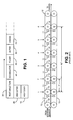
- each stopping station In the prior art buffer depicted in Fig. 2, six stopping stations are provided over a forty-two inch (1.1 m) buffer length. The space within each stopping station being seven inches (17.8 cm).
- Each of the prior art stopping stations, 1, 2, 3, 4, 5 , and 6 includes a roller nip 14 . When a document accumulation must stop at a stopping station, the respective roller nip 14 is stopped. When it is time for a document accumulation to move to the next stopping station, the respective roller nip 14 drives the accumulation downstream.
- the seven inch spacing between roller nips 14 is longer than the typical document accumulation to be transported. Accordingly, a mechanism for moving accumulations between roller nips 14 is provided.
- This mechanism is comprised of o-ring belts 13 that are driven around the length of the buffer transport system by rollers 12 .
- These o-ring belts 13 and rollers 12 run continuously and provide for transportation of accumulations between roller nips 14 at different stopping stations.
- the o-ring belts 13 continue to run even when one or more of the stopping stations and respective roller nips 14 are stopped.
- the tension of the o-ring belts 13 is light, and the surfaces in contact with the accumulations have low friction.
- rollers 12 and belts 13 are incapable of implementing any control over the stopping and starting of movement of documents in the buffer. Rather, control of the relative movement of documents within the buffer is provided by the roller nips 14 .
- the roller nips 14 are controlled in accordance with predetermined rules for moving documents within the buffer.
- a sensor 11 detects an accumulation within a first stopping station, a decision must be made about what to do with it. Accordingly, when a downstream accumulation is detected in the immediate downstream stopping station, then the accumulation is held in the first stopping station. If there is no accumulation in the immediate downstream stopping station, then the roller nip 14 moves the accumulation downstream to the next station.
- This logic is used for each of the stopping stations 1-6 for every period in the control cycle. Accordingly, documents are generally shifted towards the downstream end of the buffer as stations become available.
- the prior art arrangement shown in Fig. 2 often uses more floor space than necessary for a given mail piece creation job.
- Floor space being an important consideration for large pieces of equipment such as inserters, it is desirable to achieve the same (or greater) functionality in less space.
- FIG. 2 Another shortcoming of the arrangement in Fig. 2, occurs if more stopping stations are desired to provide more parking spaces for a user who wants to run a job with accumulations having low page counts and short documents. In this situation, there is no way to advantageously use the additional space available in the conventional buffer.
- the conventional buffer is configured to provide a fixed number of stopping stations for fixed maximum length documents, and this configuration cannot be easily adjusted. As cutters and feeders increase in speed, there may be a need for more stopping stations, particularly when a job includes low page count mail pieces. Thus, the "parking" purpose of the buffer becomes more significant to sustain increases in system throughput performance.
- a buffer transport system for staging accumulated documents produced by an input module of an inserter system prior to transfer to a downstream synchronous transport for downstream processing in the inserter system
- the buffer transport system comprising: a plurality of roller nips in series, the roller nips being spaced close enough to transfer minimum length accumulated documents between consecutive roller nips, each of the roller nips being provided with an independently controllable motor for driving the respective nip; a controller in communication with the motors; and one or more sensors in communication with the controller, the sensors being arranged to sense positions of lead and trail edges of accumulations of documents transported in the buffer transport system; the controller being arranged to determine movement of each of the plurality of roller nips for every sampling period in a periodic operating cycle, the controller being arranged, for each sampling period and for each roller nip, to: a) slave each roller nip to a group of slaved roller nips based on which roller nips are needed to control a particular accumulation of documents under
- a method for controlling a flow of document accumulations in a buffer transport system for staging accumulated documents produced by an input module of an inserter system prior to transfer to a downstream synchronous transport for downstream processing in the inserter system, the buffer transport comprising a plurality of roller nips in series the method including: driving each of the roller nips by an independently controllable motor; determining movement of each of the plurality of roller nips for every sampling period in a periodic operating cycle, further including sub steps in each sampling period and for each roller nip for: a) slaving each roller nip to a group of slaved roller nips based on which roller nips are needed to control a particular accumulation of documents under its control; b) controlling motion of each roller nip in accordance with a predetermined algorithm to bring a lead edge of the particular accumulation within a predetermined gap distance from a trail edge of a downstream accumulation of documents in the buffer transport; and driving a most downstream group of slaved n
- the system and method to be described provide a solution to these shortcomings by providing a more flexible buffer transport system that can use the available length of the buffer transport to more efficiently meet the particular needs of a given mail piece job run.
- the control of movement of the accumulations in the buffer is independent of the length of the documents.
- the number of conceptual stopping stations may be determined by the length of the buffer transport divided by the sum of a document length and the desired gap between document accumulations.
- the system includes a plurality of roller nips in series.
- the roller nips are spaced a uniform distance apart, the uniform distance being close enough to transfer minimum length accumulated documents between consecutive roller nips.
- Each of the roller nips are driven by an independently controllable motor in communication with a controller.
- a plurality of sensors also communicate with the controller.
- at least one sensor is located within the uniform distance between consecutive roller nips.
- the sensors sense positions of lead and trail edges of accumulations of documents within the buffer transport system.
- the controller for the buffer transport system operates on a periodic operating cycle. For each sampling period in the operating cycle and for each roller nip, the controller determines individual nip movement based on predetermined algorithms. First, the controller determines which other nips that the nip under consideration will be operatively slaved with. The slaving of nips together is based on which are needed to control a particular accumulation of documents under its control. The motion of the roller nip is further controlled in accordance with a predetermined algorithm to bring a lead edge of the particular accumulation within a predetermined gap distance from a trail edge of a downstream accumulation of documents in the buffer transport. For the most downstream group of slaved nips, accumulations of documents are transferred to the downstream synchronous transport based on the availability of openings on the synchronous transport.
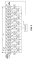
- Fig. 3 provides a schematic representation of a preferred buffer transport in accordance with the present invention.
- the buffer transport is comprised of a plurality of roller nips N, separately marked N1-N14.
- Each of the roller nips is independently driven by a servo motor M, respectively marked M1-M14, in correspondence with the fourteen roller nips N.
- the motors M are controlled by controller 100 .
- Controller 100 provides the control for the movement of the individual nips N in the system.
- the motors M include encoders to provide pulses to the controller 100 to further monitor the displacement and position of documents in the system. Since encoder pulses from the motors M results in a corresponding known displacement, downstream positions of documents can be derived if a starting point is known.
- the controller 100 preferably provides periodic displacement commands to the motors M to control the motion of the documents within the roller nips N .
- the servo motors M are preferably capable of a velocity of 100 inches per second (2.54 m/sec), and 8.6 G's of acceleration. These capabilities will allow the buffer transport to support inserter system throughput speeds up to 18,000 mail pieces per hour.
- the consecutive roller nips N are preferably spaced apart a distance sufficient that they may successfully pass the smallest length accumulation of documents from one nip to another.
- this distance, L nip may be approximately two and a half inches (6.4 cm). Accordingly, the entire buffer having nips N1-N14 would be thirty-five inches (88.9 cm) long.
- L buff will be 35 inches (88.9 cm). If a document length of four inches (10.2 cm) and gap of one inch (2.54 cm) is selected, the above equation yields that seven parking spots will be available. Thus for this particular example, more "stations" for parking accumulations are available in the thirty-five inch (88.9 cm) buffer, than the six stopping stations in the forty-two inch (1.1 m) buffer of the prior art, as depicted in Fig. 2. If a six inch (15.2 cm) document length is selected, however, it can be seen that this particular advantage of the present buffer transport system is lost, as only five parking spots will be available. Accordingly, more sets of roller nips N may be desirable for situations where it is known that greater numbers of parking spots will be needed for longer documents.
- sensors S detect the lead and trail edges of accumulations traveling in the buffer transport.
- the individual sensors are located at, or in close proximity, to the roller nips N .
- the sensors S are preferably optical sensors providing signals to the controller 100 providing positions of the passing edges of accumulated documents. Based on these sensor signals, the controller 100 can determine what roller nips N are in control of accumulations, where documents are in relation to one another, and to provide instructions accordingly.
- the accumulation location information provided by the sensors may be further supplemented by the controller 100 by taking into account the encoder displacements from motors M .
- Such encoder displacements can provide document positions subsequent in time to signals from a particular sensor S indicating the presence of a lead or trail edge.
- sensors S may be used at alternate roller nips N , instead of every one, as shown in Fig. 3.
- the controller 100 may rely more heavily on the encoder information gathered from the motors M for document position determinations.
- the controller 100 individually controls each of the motors M to maximize the space usage within the buffer transport by driving each document accumulation to a predetermined distance from the next downstream accumulation. This control scheme is carried out in a recurring operational cycle. Controller 100 performs calculations and provides instructions for each roller nip N , during each sample period in the operational cycle.
- the servo motors M are controlled via commands from controller 100 directing a particular displacement to occur during the sample period.
- the servo motors M have built-in properties of maximum velocity, maximum acceleration, and maximum deceleration. These properties limit the displacement that can be achieved during any given sample period. Further, in the preferred mode for control under the present invention, the servo motors M typically operate to achieve the desired displacement by (1) accelerating at the maximum acceleration, (2) maintaining the maximum velocity, (3) decelerating at the maximum deceleration, or (4) remaining at rest.
- the controller 100 takes account of several parameters and performs a number of calculations.
- a first parameter is X gapt , the actual gap between consecutive documents at the sampling period, t.
- X gapt is measured from the input the sensors S indicating the positions of the accumulations in the buffer transport.
- the controller 100 may also preferably supplement the sensor information with displacements measured from the servo motor M encoders. Such encoder information provides the displacement of the document that has occurred subsequent to the sensors' detection of documents' lead or trail edges.
- the controller 100 also calculates the displacement that would be required to decelerate from the current velocity, V t , to the velocity of the downstream document, V ft .
- This deceleration displacement, X decelt is significant because it would be undesirable to overshoot the desired gap, and possibly crash into the downstream accumulation.
- the following logic is used to determine the acceleration, A t , to be applied the motors M to achieve the desired displacement for that sampling period. If the roller nip is moving, and the actual gap between documents is equal to, or less than, the distance required to decelerate from the current velocity to the velocity of the downstream document, then the controller will command the motor M to decelerate at the maximum deceleration, d. This logic is directed towards preventing the document from encroaching on the desired gap, or from crashing into the downstream document.
- this first set of conditions is not present, then a next set of conditions is tested. If the actual gap between documents is greater than the distance required to decelerate from the current velocity to the velocity of the downstream document, and the current velocity is less than the maximum velocity, then motor M is commanded to accelerate at the maximum acceleration, a. This logic is designed to bring the document to the predetermined gap distance as quickly as possible.
- the document is continuously driven to a position where it is upstream of the downstream document by the predetermined gap distance, g.
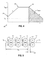
- FIG. 4 An exemplary motion profile for a document controlled in accordance with this motion control logic is depicted in Fig. 4.
- the vertical axis of profile 200 is the speed of a document traveling in the buffer transport, while the horizontal axis represents time.
- the profile begins at point 201 , where the above algorithm has determined that the distance to the downstream document is great enough that the maximum acceleration, a, should be applied. For subsequent sample periods, up until point 202 on the motion profile, the distance between documents continues to be sufficiently large that maximum acceleration is applied.
- the document has reached the maximum velocity, V max , and no more acceleration can be applied. For the interval subsequent to point 202, sufficient distance exists between documents that the maximum velocity V max is maintained.
- V max the maximum velocity
- the displacement required to decelerate from the current velocity to the velocity of the downstream document has been determined to be equal to, or greater than, the actual distance to the downstream document.
- the shaded area labeled X decelt' represents this displacement that would be required to slow to the velocity Vft'.
- the maximum deceleration, d is applied by the servo motors M , controlling the document.
- a special circumstance for control of nips N arises for the most downstream group of roller nips in the buffer transport. For that group, there will be no downstream document in the buffer transport from which to determine a motion profile as described above. Rather, transfers of document accumulations to the synchronous inserter chassis transport from that group of nips is based on the synchronous timing and availability of spaces on the synchronous chassis transport.
- the motion control algorithms eventually cause upstream documents to stop at their places within the buffer.
- the buffer will fill with the maximum number of parked document accumulations, separated by the predetermined gaps.
- the input modules upstream of the buffer transport may be instructed to cease creation of new document accumulations. Accumulations that were already in progress are parked in the available stations in the buffer and the accumulator. Alternatively, the input modules may continue to create enough document accumulations to fill all of the remaining stopping stations, before being shut down. Under this alternative embodiment, the largest number of document accumulations will be immediately available for transfer to the synchronous transport when the system restarts.
- the motion control algorithms above apply to a group of roller nips N that are in contact with the document during the sample period.
- the group of roller nips N are slaved together, one of the roller nips N being designated a master, with which the others are required to act in unison.
- the controller assesses whether each roller nip N is a master or a slave for that period, and if a slave, which master it follows.
- all roller nips N accelerate at maximum acceleration, a, to reach the maximum velocity, V max .
- the controller 100 uses the following logic to determine the master-slave relationship, as shown in reference to Fig. 5.
- the master-slave relationships are determined as follows:
- This four-step cycle is repeated for each subsequent document transported by nip N .
- the controller insures that the appropriate nips N are used to control the motion of the document accumulations, while performing the motion profiles previously discussed.
- the preferred embodiment of the invention described herein makes more efficient use of space than the prior art system described herein. Also, the positive control provided by the servo controlled nips N eliminates some unreliability that resulted from the prior art system's use of the continuously running o-ring belts.
Landscapes
- Engineering & Computer Science (AREA)
- Mechanical Engineering (AREA)
- Delivering By Means Of Belts And Rollers (AREA)
Applications Claiming Priority (2)
| Application Number | Priority Date | Filing Date | Title |
|---|---|---|---|
| US329031 | 1994-10-25 | ||
| US10/329,031 US6687570B1 (en) | 2002-12-24 | 2002-12-24 | Station independent buffer transport for an inserter system |
Publications (2)
| Publication Number | Publication Date |
|---|---|
| EP1433733A2 true EP1433733A2 (de) | 2004-06-30 |
| EP1433733A3 EP1433733A3 (de) | 2005-09-14 |
Family
ID=30443993
Family Applications (1)
| Application Number | Title | Priority Date | Filing Date |
|---|---|---|---|
| EP03029666A Withdrawn EP1433733A3 (de) | 2002-12-24 | 2003-12-23 | Fexibles Speicherfördersystem zum Anordnen von gesammelten Dokumenten |
Country Status (2)
| Country | Link |
|---|---|
| US (1) | US6687570B1 (de) |
| EP (1) | EP1433733A3 (de) |
Cited By (1)
| Publication number | Priority date | Publication date | Assignee | Title |
|---|---|---|---|---|
| DE102010043063A1 (de) | 2010-10-28 | 2012-05-03 | Böwe Systec Gmbh | Vorrichtung und Verfahren zum Puffern einer Mehrzahl von Gütern oder Gutgruppen und Papierhandhabungsanlage mit derselben |
Families Citing this family (22)
| Publication number | Priority date | Publication date | Assignee | Title |
|---|---|---|---|---|
| US7079511B2 (en) * | 2000-12-06 | 2006-07-18 | Qualcomm, Incorporated | Method and apparatus for handoff of a wireless packet data services connection |
| DE10231521B4 (de) * | 2002-07-12 | 2005-12-08 | Man Roland Druckmaschinen Ag | Vorrichtung zum Positionieren eines Schlittens zum Be- oder Entladen einer Wickelrolle, wie Bedruckstoffbahnen für Rollenrotationsdruckmaschinen |
| US6792332B1 (en) * | 2003-06-27 | 2004-09-14 | Pitney Bowes Inc. | Method for dynamic acceleration in an article transporting system |
| DE10342464B3 (de) * | 2003-09-15 | 2005-04-28 | Siemens Ag | Verfahren zum Sortieren von Sendungen nach der Verteilerreihenfolge |
| US20060024112A1 (en) * | 2004-07-27 | 2006-02-02 | Mattern James M | High speed parallel printing using meters and intelligent sorting of printed materials |
| US7464931B2 (en) * | 2005-03-31 | 2008-12-16 | Heidelberger Druckmaschinen Ag | Apparatus for positioning a trailing edge of sheets |
| DE102005015095A1 (de) * | 2005-04-01 | 2006-10-05 | Heidelberger Druckmaschinen Ag | Vorrichtung zum Positionieren einer Hinterkante von Bogen |
| EP1953104B1 (de) | 2007-01-31 | 2010-09-08 | Neopost Technologies | Mehrstationssystem und Verfahren zur Verarbeitung von Papierpostsendungen |
| JP4913680B2 (ja) * | 2007-06-22 | 2012-04-11 | 株式会社リコー | カール矯正装置および画像形成装置 |
| JP5149074B2 (ja) * | 2008-05-22 | 2013-02-20 | デュプロ精工株式会社 | 用紙搬送装置及び用紙搬送システム |
| US7913989B2 (en) * | 2008-10-16 | 2011-03-29 | Goss International Americas, Inc | Section for transporting printed products of variable cutoffs in a printing press folder |
| US8602957B2 (en) * | 2008-10-16 | 2013-12-10 | Goss International Americas, Inc. | Incremental velocity changing apparatus for transporting printed products in a printing press folder |
| JP5209443B2 (ja) * | 2008-11-04 | 2013-06-12 | 株式会社小森コーポレーション | 処理機の駆動制御方法及び駆動制御装置 |
| US8100038B2 (en) | 2008-11-19 | 2012-01-24 | Goss International Americas, Inc. | Folder for adjustably tensioning a web and method of adjusting web tension as a web is cut |
| FR2944268B1 (fr) * | 2009-04-09 | 2011-04-15 | Solystic | Dispositif d'alimentation d'objets plats avec un synchronisateur a plusieurs motorisations |
| JP5556475B2 (ja) * | 2010-07-27 | 2014-07-23 | セイコーエプソン株式会社 | ターゲット搬送装置及び記録装置 |
| WO2012167050A2 (en) * | 2011-06-03 | 2012-12-06 | Pitney Bowes Inc. | Inter-machine buffer for mailpiece fabrication system |
| ITBO20110515A1 (it) * | 2011-09-09 | 2013-03-10 | C M C Srl | Buffer dinamico per sistema di imbustamento in continuo |
| EP3003703B1 (de) * | 2013-05-29 | 2017-08-23 | Bobst Mex Sa | Verarbeitungseinheit mit endlosbandauflage, und damit ausgestattete maschine zur herstellung von verpackungen |
| EP3067302B1 (de) * | 2015-03-12 | 2017-09-27 | Kabushiki Kaisha Toshiba | Fördervorrichtung |
| JP6863322B2 (ja) * | 2018-03-22 | 2021-04-21 | 京セラドキュメントソリューションズ株式会社 | 中継搬送装置および画像形成システム |
| AU2022390166A1 (en) | 2021-11-18 | 2024-08-29 | Dmt Solutions Global Corporation | Card processing and attaching system |
Citations (1)
| Publication number | Priority date | Publication date | Assignee | Title |
|---|---|---|---|---|
| WO2000078471A1 (en) * | 1999-06-22 | 2000-12-28 | Solystic | Device for transferring flat objects with an injector comprising elastically deformable wheels |
Family Cites Families (14)
| Publication number | Priority date | Publication date | Assignee | Title |
|---|---|---|---|---|
| US4451027A (en) * | 1980-01-09 | 1984-05-29 | Burroughs Corp. | Constant spacing document feeder |
| DE3443944C1 (de) * | 1984-12-01 | 1986-05-22 | SKF GmbH, 8720 Schweinfurt | Fördervorrichtung für Stückgut |
| GB2230244B (en) * | 1989-04-06 | 1993-01-20 | Unisys Corp | Document transportation and detection apparatus. |
| JPH06156797A (ja) * | 1992-11-18 | 1994-06-03 | Fuji Xerox Co Ltd | 画像形成装置の用紙搬送装置 |
| EP0825142B1 (de) * | 1993-08-16 | 2002-12-04 | Agfa Corporation | Verfahren und Apparat zum Zwischenspeichern von Medien |
| US5465955A (en) * | 1994-08-08 | 1995-11-14 | Bayer Corporation | Method and apparatus for an external media buffer |
| US5575466A (en) * | 1994-11-21 | 1996-11-19 | Unisys Corporation | Document transport with variable pinch-roll force for gap adjust |
| US5826869A (en) * | 1995-10-18 | 1998-10-27 | Bell & Howell Phillipsburg Company | High throughput document-processing machine having dynamic speed control |
| US6085892A (en) * | 1997-02-07 | 2000-07-11 | Quantum Conveyor Systems, Inc. | High speed sorting/diverting apparatus, an apparatus controller and systems using same |
| JP3520169B2 (ja) * | 1997-03-04 | 2004-04-19 | 株式会社リコー | 画像形成装置 |
| US6176483B1 (en) * | 1997-03-12 | 2001-01-23 | Bell & Howell Mail And Messaging Technologies Company | High speed document separator and sequencing apparatus |
| JP3378462B2 (ja) * | 1997-03-31 | 2003-02-17 | 伊東電機株式会社 | コンベアシステム及びその制御方法 |
| US5826157A (en) * | 1997-07-31 | 1998-10-20 | Xerox Corporation | Sychronized paper feeding across module boundaries with timed clock ticks |
| JP2001139204A (ja) * | 1999-11-16 | 2001-05-22 | Matsushita Electric Ind Co Ltd | 画像形成装置におけるシート材の排出機構 |
-
2002
- 2002-12-24 US US10/329,031 patent/US6687570B1/en not_active Expired - Lifetime
-
2003
- 2003-12-23 EP EP03029666A patent/EP1433733A3/de not_active Withdrawn
Patent Citations (1)
| Publication number | Priority date | Publication date | Assignee | Title |
|---|---|---|---|---|
| WO2000078471A1 (en) * | 1999-06-22 | 2000-12-28 | Solystic | Device for transferring flat objects with an injector comprising elastically deformable wheels |
Cited By (3)
| Publication number | Priority date | Publication date | Assignee | Title |
|---|---|---|---|---|
| DE102010043063A1 (de) | 2010-10-28 | 2012-05-03 | Böwe Systec Gmbh | Vorrichtung und Verfahren zum Puffern einer Mehrzahl von Gütern oder Gutgruppen und Papierhandhabungsanlage mit derselben |
| WO2012055761A1 (de) | 2010-10-28 | 2012-05-03 | Böwe Systec Gmbh | Vorrichtung und verfahren zum puffern einer mehrzahl von gütern oder gutgruppen und papierhandhabungsanlage mit derselben |
| DE102010043063B4 (de) * | 2010-10-28 | 2012-11-08 | Böwe Systec Gmbh | Vorrichtung und Verfahren zum Puffern einer Mehrzahl von Gütern oder Gutgruppen und Papierhandhabungsanlage mit derselben |
Also Published As
| Publication number | Publication date |
|---|---|
| EP1433733A3 (de) | 2005-09-14 |
| US6687570B1 (en) | 2004-02-03 |
Similar Documents
| Publication | Publication Date | Title |
|---|---|---|
| US6687570B1 (en) | Station independent buffer transport for an inserter system | |
| US6792332B1 (en) | Method for dynamic acceleration in an article transporting system | |
| US5826869A (en) | High throughput document-processing machine having dynamic speed control | |
| EP1481817B1 (de) | Kuvertiersystem mit einem Rotationsschneidegerät | |
| US8540235B2 (en) | Conveying apparatus for envelopes and related methods | |
| EP1683651B1 (de) | Bewegungskontrolle für die Eingabe eines Hochgeschwindigkeitskuvertierers | |
| GB2165824A (en) | Shingling and stacking of conveyed sheet material with pre-shingling control of sheet feed | |
| US6687569B1 (en) | Configurable multi-station buffer transport for an inserter system | |
| EP1927563B1 (de) | Verfahren und Vorrichtung zur Erhöhung des Durchsatzes eines Schneidegerätes mittels Ausgangsbewegungsprofil | |
| US7232122B2 (en) | Jam detection method and system for an inserter | |
| US20110169217A1 (en) | Method and Device for Transporting Paper Within a Paper Handling Installation from a First Conveyor to a Second Conveyor | |
| EP1577242B1 (de) | System und Verfahren zum Beschicken eines Kuvertiersystem mit Blättern unter Verwendung einer Hochgeschwindigkeitsschneideinrichtung und rechtwinkliger Drehung | |
| US6418357B1 (en) | Method for synchronizing an envelope inserter | |
| US9221295B2 (en) | Apparatus and method to control material converting and envelope stuffing | |
| US6802504B2 (en) | Diagnostic methodology for an inserting machine | |
| EP1334935B1 (de) | Vorrichtung zum Handhaben von Dokumenten mit dynamischem Einführungsmechanismus und entsprechendes Verfahren | |
| CA2472870C (en) | Apparatus and method for accumulating sheets | |
| JPH07196221A (ja) | 段ボールシートのシングリング制御方法 | |
| US6971217B2 (en) | Method and device for controlling a wrapping machine for printed products | |
| EP1798176A1 (de) | Vorrichtung und Verfahren zur Sequenzierung beim Schneiden | |
| US8628080B2 (en) | Method and system for controlling a staging transport in a mail processing machine | |
| CA2558631A1 (en) | Apparatus and method for accumulating sheets |
Legal Events
| Date | Code | Title | Description |
|---|---|---|---|
| PUAI | Public reference made under article 153(3) epc to a published international application that has entered the european phase |
Free format text: ORIGINAL CODE: 0009012 |
|
| AK | Designated contracting states |
Kind code of ref document: A2 Designated state(s): AT BE BG CH CY CZ DE DK EE ES FI FR GB GR HU IE IT LI LU MC NL PT RO SE SI SK TR |
|
| AX | Request for extension of the european patent |
Extension state: AL LT LV MK |
|
| PUAL | Search report despatched |
Free format text: ORIGINAL CODE: 0009013 |
|
| AK | Designated contracting states |
Kind code of ref document: A3 Designated state(s): AT BE BG CH CY CZ DE DK EE ES FI FR GB GR HU IE IT LI LU MC NL PT RO SE SI SK TR |
|
| AX | Request for extension of the european patent |
Extension state: AL LT LV MK |
|
| 17P | Request for examination filed |
Effective date: 20060227 |
|
| AKX | Designation fees paid |
Designated state(s): DE FR GB |
|
| 17Q | First examination report despatched |
Effective date: 20070718 |
|
| R17C | First examination report despatched (corrected) |
Effective date: 20100317 |
|
| STAA | Information on the status of an ep patent application or granted ep patent |
Free format text: STATUS: THE APPLICATION HAS BEEN WITHDRAWN |
|
| 18W | Application withdrawn |
Effective date: 20100426 |