EP1433739A2 - Apparat und Verfahren für die Erdung einer Bedienungsperson, die komprimierten Kraftstoff tankt - Google Patents
Apparat und Verfahren für die Erdung einer Bedienungsperson, die komprimierten Kraftstoff tankt Download PDFInfo
- Publication number
- EP1433739A2 EP1433739A2 EP04006372A EP04006372A EP1433739A2 EP 1433739 A2 EP1433739 A2 EP 1433739A2 EP 04006372 A EP04006372 A EP 04006372A EP 04006372 A EP04006372 A EP 04006372A EP 1433739 A2 EP1433739 A2 EP 1433739A2
- Authority
- EP
- European Patent Office
- Prior art keywords
- fuel
- grounding
- nozzle
- operator
- fuel tank
- Prior art date
- Legal status (The legal status is an assumption and is not a legal conclusion. Google has not performed a legal analysis and makes no representation as to the accuracy of the status listed.)
- Granted
Links
Images


Classifications
-
- B—PERFORMING OPERATIONS; TRANSPORTING
- B67—OPENING, CLOSING OR CLEANING BOTTLES, JARS OR SIMILAR CONTAINERS; LIQUID HANDLING
- B67D—DISPENSING, DELIVERING OR TRANSFERRING LIQUIDS, NOT OTHERWISE PROVIDED FOR
- B67D7/00—Apparatus or devices for transferring liquids from bulk storage containers or reservoirs into vehicles or into portable containers, e.g. for retail sale purposes
- B67D7/06—Details or accessories
- B67D7/32—Arrangements of safety or warning devices; Means for preventing unauthorised delivery of liquid
- B67D7/3236—Arrangements of safety or warning devices; Means for preventing unauthorised delivery of liquid relating to electrostatic charges
-
- F—MECHANICAL ENGINEERING; LIGHTING; HEATING; WEAPONS; BLASTING
- F17—STORING OR DISTRIBUTING GASES OR LIQUIDS
- F17C—VESSELS FOR CONTAINING OR STORING COMPRESSED, LIQUEFIED OR SOLIDIFIED GASES; FIXED-CAPACITY GAS-HOLDERS; FILLING VESSELS WITH, OR DISCHARGING FROM VESSELS, COMPRESSED, LIQUEFIED, OR SOLIDIFIED GASES
- F17C13/00—Details of vessels or of the filling or discharging of vessels
- F17C13/12—Arrangements or mounting of devices for preventing or minimising the effect of explosion ; Other safety measures
- F17C13/123—Arrangements or mounting of devices for preventing or minimising the effect of explosion ; Other safety measures for gas bottles, cylinders or reservoirs for tank vehicles or for railway tank wagons
-
- F—MECHANICAL ENGINEERING; LIGHTING; HEATING; WEAPONS; BLASTING
- F17—STORING OR DISTRIBUTING GASES OR LIQUIDS
- F17C—VESSELS FOR CONTAINING OR STORING COMPRESSED, LIQUEFIED OR SOLIDIFIED GASES; FIXED-CAPACITY GAS-HOLDERS; FILLING VESSELS WITH, OR DISCHARGING FROM VESSELS, COMPRESSED, LIQUEFIED, OR SOLIDIFIED GASES
- F17C5/00—Methods or apparatus for filling containers with liquefied, solidified, or compressed gases under pressures
-
- F—MECHANICAL ENGINEERING; LIGHTING; HEATING; WEAPONS; BLASTING
- F17—STORING OR DISTRIBUTING GASES OR LIQUIDS
- F17C—VESSELS FOR CONTAINING OR STORING COMPRESSED, LIQUEFIED OR SOLIDIFIED GASES; FIXED-CAPACITY GAS-HOLDERS; FILLING VESSELS WITH, OR DISCHARGING FROM VESSELS, COMPRESSED, LIQUEFIED, OR SOLIDIFIED GASES
- F17C2221/00—Handled fluid, in particular type of fluid
- F17C2221/01—Pure fluids
- F17C2221/011—Oxygen
-
- F—MECHANICAL ENGINEERING; LIGHTING; HEATING; WEAPONS; BLASTING
- F17—STORING OR DISTRIBUTING GASES OR LIQUIDS
- F17C—VESSELS FOR CONTAINING OR STORING COMPRESSED, LIQUEFIED OR SOLIDIFIED GASES; FIXED-CAPACITY GAS-HOLDERS; FILLING VESSELS WITH, OR DISCHARGING FROM VESSELS, COMPRESSED, LIQUEFIED, OR SOLIDIFIED GASES
- F17C2221/00—Handled fluid, in particular type of fluid
- F17C2221/03—Mixtures
- F17C2221/032—Hydrocarbons
- F17C2221/033—Methane, e.g. natural gas, CNG, LNG, GNL, GNC, PLNG
-
- F—MECHANICAL ENGINEERING; LIGHTING; HEATING; WEAPONS; BLASTING
- F17—STORING OR DISTRIBUTING GASES OR LIQUIDS
- F17C—VESSELS FOR CONTAINING OR STORING COMPRESSED, LIQUEFIED OR SOLIDIFIED GASES; FIXED-CAPACITY GAS-HOLDERS; FILLING VESSELS WITH, OR DISCHARGING FROM VESSELS, COMPRESSED, LIQUEFIED, OR SOLIDIFIED GASES
- F17C2260/00—Purposes of gas storage and gas handling
- F17C2260/04—Reducing risks and environmental impact
- F17C2260/042—Reducing risk of explosion
-
- F—MECHANICAL ENGINEERING; LIGHTING; HEATING; WEAPONS; BLASTING
- F17—STORING OR DISTRIBUTING GASES OR LIQUIDS
- F17C—VESSELS FOR CONTAINING OR STORING COMPRESSED, LIQUEFIED OR SOLIDIFIED GASES; FIXED-CAPACITY GAS-HOLDERS; FILLING VESSELS WITH, OR DISCHARGING FROM VESSELS, COMPRESSED, LIQUEFIED, OR SOLIDIFIED GASES
- F17C2265/00—Effects achieved by gas storage or gas handling
- F17C2265/06—Fluid distribution
- F17C2265/065—Fluid distribution for refuelling vehicle fuel tanks
-
- F—MECHANICAL ENGINEERING; LIGHTING; HEATING; WEAPONS; BLASTING
- F17—STORING OR DISTRIBUTING GASES OR LIQUIDS
- F17C—VESSELS FOR CONTAINING OR STORING COMPRESSED, LIQUEFIED OR SOLIDIFIED GASES; FIXED-CAPACITY GAS-HOLDERS; FILLING VESSELS WITH, OR DISCHARGING FROM VESSELS, COMPRESSED, LIQUEFIED, OR SOLIDIFIED GASES
- F17C2270/00—Applications
- F17C2270/01—Applications for fluid transport or storage
- F17C2270/0134—Applications for fluid transport or storage placed above the ground
- F17C2270/0139—Fuel stations
Definitions
- the present invention is directed to apparatus and methods for fueling fuel tanks with compressed fuel.
- the present invention is directed to the grounding of an operator during the compressed fuel fueling process.
- Fueling the fuel tanks of vehicles and other mobile apparatus with gaseous fuels such as hydrogen or compressed natural gas can be accomplished rapidly by discharging the fuel from high pressure storage vessels into, for example, the fuel tank or storage vessel in the vehicle or other mobile apparatus requiring fuel. It is imperative that the fuel be delivered safely to the vehicle.
- the point of the fueling process that may pose a potential hazard occurs when the operator disconnects the fuel fill nozzle from the vehicle. The operator may have built up static charge upon his or her person. If there is a leak of fuel from the station or vehicle, then, as the operator tries to remove the nozzle, a spark from a static discharge may ignite the gaseous fuel.
- the present invention is directed to the grounding of such an operator subsequent to the filling operation and prior to removal of the fuel fill nozzle.
- the operator is either notified that he must ground himself prior to removal of the nozzle, or the nozzle itself is locked into the vehicle port.
- Automatic nozzles that lock and unlock to a vehicle port have been built for natural gas vehicle (NGV) service, for example, the WEH GmbH of Germany, nozzle type WEH TK 18, but none is locked or unlocked by action of grounding.
- NVM natural gas vehicle
- the present invention addresses grounding of an operator while filling a fuel cell tank with hydrogen, all embodiments of the present invention apply equally well to filling a fuel tank with a flammable gas or flammable liquid that emits flammable vapors, such as gasoline. It is believed that the present invention is the first attempt to solve the problem of potential static discharge at the end of a vehicle fill process by the grounding of the fuel fill operator.
- the first embodiment of the present invention is directed to a safety system for grounding an operator at a fueling station prior to removing a fuel fill nozzle from a fuel tank upon completion of a fuel filling operation.
- the safety system includes a fuel tank port in communication with the fuel tank for receiving and retaining the fuel fill nozzle during the fuel filling operation.
- the safety system further includes a grounding device adjacent to the fuel tank port which includes a grounding switch having a contact member that receives physical contact by the operator. Physical contact of the contact member by the operator activates the grounding switch.
- a releasable interlock is also included that provides a lock position wherein the nozzle is locked into the port upon insertion of the nozzle into the port and a release position wherein the nozzle is releasable from the port upon completion of the fuel filling operation and after physical contact of the contact member is accomplished.
- Accidental ignition of fuel due to static discharge is thereby prevented.
- the grounding device is located at least two centimeters from the nozzle.
- the fuel source contain a compressed fuel and the fuel is hydrogen.
- the releasable interlock may be a manually activated nozzle lever, wherein movement of the nozzle lever in a first direction locks the nozzle to the fuel tank port and wherein movement of the nozzle lever in a second direction unlocks the nozzle from the fuel tank port only upon activation of the grounding switch.
- the first direction and the second direction are opposed, i.e., are directed 180 degrees from one another.
- the first direction may be toward the left and the second direction may be toward the right, although such feature is not essential or required. Many combinations of first and second directions can be engineered without undue experimentation.
- a timer may be included that is connected to the releasable interlock where the timer provides for the releasable interlock to remain in the release position for a limited time period subsequent to activation of the grounding switch.
- the timer provides for the releasable interlock to remain in the locked position at all other times when the nozzle is received in the port.
- the limited time period may be about one to three hundred seconds and preferably about five seconds.
- An indicator to provide indication that the nozzle may safely be removed from the receptacle may be provided where the indicator provides indication during the limited time period.
- the grounding switch may be integral to the releasable interlock.
- the releasable interlock may be a lever that moves from the lock position to the release position, whereby the lever blocks the nozzle from removal from the fuel tank port until moved from the lock position to the release position.
- a grounding verification switch adjacent to the nozzle and a timer connected to the releasable interlock may also be provided.
- the grounding verification switch is connected to a fuel controller where the fuel controller enables flow of the fuel from the nozzle only during activation of the grounding verification switch and the timer provides for the releasable interlock to remain in the release position for a limited time period subsequent to release of the grounding verification switch.
- the grounding verification switch may include an activation handle on the nozzle that controls flow of fuel.
- a grounding verification switch may be included along with a timer.
- the grounding verification switch connects to the fuel controller, the fuel controller enabling flow of the fuel from the nozzle only during activation of the grounding verification switch.
- the timer is connected to the fuel controller and provides for flow of fuel to resume once halted by release of the grounding verification switch for a limited time period subsequent to release of the grounding verification switch.
- the fuel controller provides for no fuel to flow after the limited time period has been reached until the grounding switch is re-activated.
- a safety system for grounding an operator at a fueling station during a fuel filling operation includes a fuel tank port in communication with a fuel tank for receiving a fuel fill nozzle, a grounding device adjacent to the fuel tank port, the grounding device including a grounding switch having a contact member to receive physical contact by the operator. Physical contact of the contact member activates the grounding switch.
- a fuel controller is provided for providing fuel flow through the nozzle only when the grounding switch is continuously activated.
- a safety system for grounding an operator at a fueling station during a fuel filling operation includes a fuel tank port in communication with a fuel tank for receiving a fuel fill nozzle, a grounding device adjacent to the fuel tank port, the grounding device including a contact member connected to ground which is adapted to receive physical contact by the operator, and a fuel controller for controlling fuel flow through the nozzle.
- the fuel controller provides for a flow of fuel, and provides a signal when the controller provides for fuel to stop flowing.
- An indicator is also provided that indicates to the operator, immediately upon receiving the signal, that grounding must take place prior to removal of the nozzle.
- a method for grounding an operator at a fueling station includes the steps of providing the apparatus of the first embodiment, withdrawing the fuel fill nozzle from a fuel source boot, inserting the fuel fill nozzle into the fuel tank port whereby the nozzle is locked into the fuel tank port, filling the fuel tank with fuel from a fuel source, contacting the contact member to activate the grounding switch of the grounding member to release the releasable interlock, and withdrawing the nozzle from the port.
- the operator may also have to contact a grounding verification switch that is connected to ground during the activation process. The operator may have a limited time period in which he or she must remove the nozzle from the port after the fueling and grounding process is complete.
- Another method for grounding an operator at a fueling station during a fuel filling operation includes providing a fuel tank port in communication with a fuel tank for receiving a fuel fill nozzle during the fuel filling operation.
- a grounding device adjacent to the fuel tank port is provided wherein the grounding device includes a grounding switch having a contact member to receive physical contact by the operator, wherein physical contact of the contact member activates the grounding switch.
- a fuel controller is provided that is activatable by the grounding switch to provide fuel flow through the nozzle only when the grounding switch is continuously activated. The contact member is physically contacted to activate the grounding switch which activates the fuel controller to provide fuel flow.
- a method for grounding an operator at a fueling station during a fuel filling operation includes providing a fuel fill nozzle connected to a fuel source, providing a fuel tank port in communication with a fuel tank for receiving the fuel fill nozzle, and providing a grounding device adjacent to the fuel tank port, the grounding device including a contact member connected to ground which is adapted to receive physical contact by the operator.
- a fuel controller for controlling fuel flow through the nozzle is also provided where the fuel controller provides a signal when the controller provides fuel to stop flowing.
- An indicator is provided that indicates to the operator, immediately upon receiving the signal, that grounding must take place prior to removal of the nozzle.
- the nozzle is inserted into the fuel tank port, a desired quantity of fuel is input into the fuel tank via the fuel controller until the desired quantity of fuel has been transferred or the fuel tank has reached capacity.
- the signal from the controller to the indicator is provided to indicate to the operator that the operator must contact the contact member. The operator contacts the contact member and the nozzle is removed from the fuel tank port.
- FIG. 1 is a simplified schematic diagram of a fueling station in combination with a fuel dispenser and fuel storage vessel in accordance with one preferred embodiment of the present invention.
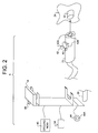
- FIG. 2 is a simplified view of a nozzle and port in accordance with one preferred embodiment of the present invention, for use in the fuel filling station of FIG. 1.
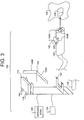
- FIG. 3 is a simplified view of a nozzle and port in accordance with a second preferred embodiment of the present invention, for use in the fuel filling station of FIG. 1.
- FIG. 4 is a simplified view of a nozzle and port in accordance with a third preferred embodiment of the present invention, for use in the fuel filling station of FIG. 1.
- FIG. 5 is a simplified view of a nozzle and port in accordance with a fourth preferred embodiment of the present invention, for use in the fuel filling station of FIG. 1.
- FIG. 6 is a simplified view of a nozzle and port in accordance with a fifth preferred embodiment of the present invention, for use in the fuel filling station of FIG. 1.
- the present invention is directed to apparatus and methods for grounding an operator during a fuel filling operation immediately before removing the fuel fill nozzle from the vehicle by the operator.
- static discharge from the operator during the nozzle disconnection process will not likely cause ignition of fuel or vapor that has leaked from the fuel nozzle/vehicle fuel port area during the normal fueling process.
- While this invention is primarily directed to a fuel filling process for filling hydrogen gas in a fuel cell fuel tank, the present invention would apply equally well to filling a fuel tank with any flammable gas or flammable liquid that emits flammable vapors, such as gasoline.
- grounding of the operator occur at a grounding point adjacent to the fuel tank port of the vehicle.
- adjacent means a distance that is any suitable distance between the fuel tank port and the grounding point.
- the distance between the dispenser and the fuel tank port or, for example, two to ten feet or even more may typically be appropriate. Any distance of at least two centimeters will likely allow for proper grounding in accordance with this invention.
- FIG. 1 a safety system 5 for grounding an operator at a fueling station 10 prior to removing the fuel fill nozzle 22 from the fuel tank port 32 of the vehicle 24.
- vehicle 24 means a vehicle such as an automobile or other mobile or portable apparatus that has a fuel tank 26 that is to be filled with a flammable gas or liquid fuel.
- the fueling station 10 consists of a station controller 12 which may be located in a fuel dispenser 14 or elsewhere in the station 10.
- the station 10 will also include a source of compressed fuel such as a fuel storage vessel 16, fuel flow controller 18 for controlling flow of fuel, and a monitor 20 for the monitoring flow of fuel. Again, the fuel flow controller 18 and monitor 20 may be located in the dispenser 14, or elsewhere in the station 10.
- the fuel flows from the fuel storage vessel 16 through a fuel conduit 28 to a fuel flow nozzle 22.
- the fuel flow nozzle 22 mates with the fuel tank port 32 in the vehicle 24.
- the dispenser will also have a resting place, or boot, 33, for supporting the nozzle when not filling the vehicle.
- a primary inventive aspect of one preferred embodiment of the safety system 5 of the present invention is the use of a releasable interlock 42 for the nozzle 22 with respect to the port 32.
- the releasable interlock 42 functions to lock the fuel fill nozzle 22, using manual, pneumatic or other form of automatic function, as generally known, that causes the fuel fill nozzle 22 to securely lock to the vehicle fuel tank nozzle port 32 unless and until the operator has grounded him or herself to the station by a grounding device 44.
- the grounding device 44 includes a contact member 44A and a grounding switch 40 wherein physical contact of the contact member 44A, preferably contact by skin, activates the grounding switch 40 to cause (for an automatic version; see below) or allow (for a manual version; see below) the releasable interlock 42 to move from a lock position 42A to a release position 42B to provide that the fuel fill nozzle 22 be releasable such that it can be removed from the fuel tank nozzle port 32 by the operator.
- the contact member 44A of the grounding device 44 sense actual physical skin-to-contact member contact such that electrical contact from the operator to ground is made.
- the present invention also anticipates the use of a grounding switch 40 that only requires mechanical movement to be activated and does not necessarily sense the electrical contact.
- the operator contacts the contact member 44A which is connected to ground, but the actual switching occurs based on mechanical movement of an element connected to the grounding switch 40, e.g., the contact member 44A.
- Movement of the releasable interlock 42 from the lock position 42A to the release position 42B can be accomplished manually or automatically using an optional automatic locking device 43 driven by, for example, pneumatics, electro-mechanics, e.g., with the use of motors, or by any other form of providing a mechanical locking function automatically.
- an optional automatic locking device 43 driven by, for example, pneumatics, electro-mechanics, e.g., with the use of motors, or by any other form of providing a mechanical locking function automatically.
- the grounding device 44 can be performed in a number of ways in accordance with the present invention.
- the grounding device 44 may include a grounded button, a grounded lever that requires, for example, lifting or sliding to activate, a grounded handle on a rotatable switch, a grounded touch sensitive point on the dispenser, or any other similar device.
- the grounding device 44 can be located so that it interferes with returning the nozzle to the nozzle boot 32.
- the contact member 44A is electrically connected to ground (earth) and is located on the grounding device 44 such that the when the operator moves the lever, button, etc., of the grounding switch 40, the operator must make physical contact with the contact member and is thereby electrically connected to ground.
- the releasable interlock 42 causes the fuel fill nozzle 32 to be releasable from the fuel tank nozzle port 32.
- Fig. 3 depicts an alternate safety system 105 of the present invention.
- like parts with respect to the first embodiment will be designated as a one hundred series number.
- nozzle 22 in the first embodiment will be designated nozzle 122 in this embodiment.
- the switch 140 in combination with the contact member 144 may be a lever that activates the switch 140 where the lever is located so that it must be in the release position 144B (i.e., a grounded verified position) in order to remove or replace the nozzle 122 in the nozzle boot.
- the contact member 144A in this embodiment, is integral to the lever, such that when the operator contacts the lever to move the lever, the operator must contact the contact member 144A and thereby grounds himself.
- a grounding verification switch 136 may be used such that fueling may only proceed while the grounding verification switch 136 is activated (shown in FIG. 3 only).
- the grounding verification switch 136 is connected to the fuel flow controller 18 (FIG. 1) which allows flow of fuel only when the grounding verification switch 136 is activated.
- the grounding verification switch 136 is connected to the contact member 144A which is electrically connected to ground. In this manner, the operator must be continuously grounded during the fueling process while fuel is flowing. A timer as described below may be incorporated.
- a timer 34, 134 may be included as part of the safety system 5, 105 of the present invention.
- the timer 34, 134 ensures that the operator does not generate enough static between grounding and touching of the fuel nozzle that may cause discharge of significant energy release to ignite the fuel air mixture.
- the nozzle 22, 122 is again locked by the releasable interlock 42, 142 from the release position 42B, 142B to the lock position 42A, 142A so that re-grounding of the operator is necessary for the operator to disconnect the nozzle 22, 122 from the vehicle port 32, 132.
- An indicator 45, 145 such as an indicator light, message screen, LEDs, and the like, may be used to indicate to the operator that he or she must activate the grounding device 44, 144 by contacting the contact member 44A, 144A.
- FIG. 4 depicts another alternate embodiment of the safety system 205 of the present invention.
- nozzle 22 in the first embodiment will be designated nozzle 222 in this embodiment.
- the safety system 205 includes a fuel tank port 232, a fuel fill nozzle 222, and a grounding device 244 adjacent to or near the fuel tank nozzle 232.
- the grounding device 232 includes a grounding switch 240 and has a contact member 244A to receive physical contact by the operator such that physical contact of the contact member activates the grounding switch 240.
- the grounding switch 240 is in communication with the fuel controller 18 (see FIG. 1) such that fuel is supplied, as controlled by the fuel controller 18, only when the grounding switch 240 is continuously activated.
- the grounding device i.e., the grounding switch and contact member is, in effect, a fuel activation handle.
- FIG. 5 depicts another alternate embodiment of the safety system 305 of the present invention.
- like parts with respect to the first embodiment will be designated with a three hundred series number.
- nozzle 22 in the first embodiment will be designated nozzle 322 in this embodiment.
- the safety system 305 again contains no releasable interlock.
- a fuel fill nozzle 322, a fuel tank nozzle port 332 and a grounding device 344 are included.
- the grounding device includes a contact member 344A that is connected to ground.
- the grounding device 344 also includes a grounding switch 350.
- the fuel controller 18 see FIG.
- the fuel controller 18 for controlling fuel flow through the nozzle, is included wherein when the contact member 344A of the grounding device 344 is contacted, thereby activating the grounding switch 340, the fuel controller 18 provides for fuel to flow. If the contact member 344A is released or when the fuel tank 326 has reached capacity, the fuel controller 18 causes fuel to stop flowing. The fuel controller 18 then provides a signal to an indicator 345, such as a display screen or light that indicates to the operator, immediately upon receiving the signal, that grounding must take place prior to removal of the nozzle.
- an indicator 345 such as a display screen or light that indicates to the operator, immediately upon receiving the signal, that grounding must take place prior to removal of the nozzle.
- FIG. 6 depicts another alternate embodiment of the safety system 405 of the present invention.
- nozzle 22 in the first embodiment will be designated nozzle 422 in this embodiment.
- This embodiment includes only a fuel fill nozzle 422, a fuel tank nozzle port 432, a grounding device 444, a fuel flow controller 18 (see FIG. 1), and an indicator 445.
- the fuel flow controller 18 senses that fuel is no longer flowing, either due to the fuel tank being full or the operator shutting off flow of fuel, the fuel flow controller sends a signal to the indicator 445 to indicate to the operator that he or she should contact ground prior to removal of the nozzle from the port.
- the operator places the nozzle in the port and performs the appropriate required function based on the above systems in order to withdraw the nozzle from the port.
Landscapes
- Engineering & Computer Science (AREA)
- Mechanical Engineering (AREA)
- General Engineering & Computer Science (AREA)
- Loading And Unloading Of Fuel Tanks Or Ships (AREA)
- Vehicle Cleaning, Maintenance, Repair, Refitting, And Outriggers (AREA)
- Filling Or Discharging Of Gas Storage Vessels (AREA)
- Cooling, Air Intake And Gas Exhaust, And Fuel Tank Arrangements In Propulsion Units (AREA)
Priority Applications (1)
| Application Number | Priority Date | Filing Date | Title |
|---|---|---|---|
| EP04028273A EP1533269B1 (de) | 2001-05-22 | 2002-05-15 | Apparat und Verfahren für die Erdung einer Bedienungsperson, die komprimierten Kraftstoff tankt |
Applications Claiming Priority (3)
| Application Number | Priority Date | Filing Date | Title |
|---|---|---|---|
| US09/862,259 US6401767B1 (en) | 2001-05-22 | 2001-05-22 | Apparatus and method for grounding compressed fuel fueling operator |
| US862259 | 2001-05-22 | ||
| EP02010195A EP1262449B1 (de) | 2001-05-22 | 2002-05-15 | Apparat und Verfahren für die Erdung einer Bedienungsperson, die komprimierten Kraftstoff tankt |
Related Parent Applications (2)
| Application Number | Title | Priority Date | Filing Date |
|---|---|---|---|
| EP02010195.2 Division | 2002-05-15 | ||
| EP02010195A Division EP1262449B1 (de) | 2001-05-22 | 2002-05-15 | Apparat und Verfahren für die Erdung einer Bedienungsperson, die komprimierten Kraftstoff tankt |
Related Child Applications (2)
| Application Number | Title | Priority Date | Filing Date |
|---|---|---|---|
| EP04028273A Division EP1533269B1 (de) | 2001-05-22 | 2002-05-15 | Apparat und Verfahren für die Erdung einer Bedienungsperson, die komprimierten Kraftstoff tankt |
| EP04028273.3 Division-Into | 2004-11-29 |
Publications (3)
| Publication Number | Publication Date |
|---|---|
| EP1433739A2 true EP1433739A2 (de) | 2004-06-30 |
| EP1433739A3 EP1433739A3 (de) | 2004-07-07 |
| EP1433739B1 EP1433739B1 (de) | 2005-11-09 |
Family
ID=25338061
Family Applications (3)
| Application Number | Title | Priority Date | Filing Date |
|---|---|---|---|
| EP04028273A Expired - Lifetime EP1533269B1 (de) | 2001-05-22 | 2002-05-15 | Apparat und Verfahren für die Erdung einer Bedienungsperson, die komprimierten Kraftstoff tankt |
| EP04006372A Expired - Lifetime EP1433739B1 (de) | 2001-05-22 | 2002-05-15 | Apparat und Verfahren für die Erdung einer Bedienungsperson, die komprimierten Kraftstoff tankt |
| EP02010195A Expired - Lifetime EP1262449B1 (de) | 2001-05-22 | 2002-05-15 | Apparat und Verfahren für die Erdung einer Bedienungsperson, die komprimierten Kraftstoff tankt |
Family Applications Before (1)
| Application Number | Title | Priority Date | Filing Date |
|---|---|---|---|
| EP04028273A Expired - Lifetime EP1533269B1 (de) | 2001-05-22 | 2002-05-15 | Apparat und Verfahren für die Erdung einer Bedienungsperson, die komprimierten Kraftstoff tankt |
Family Applications After (1)
| Application Number | Title | Priority Date | Filing Date |
|---|---|---|---|
| EP02010195A Expired - Lifetime EP1262449B1 (de) | 2001-05-22 | 2002-05-15 | Apparat und Verfahren für die Erdung einer Bedienungsperson, die komprimierten Kraftstoff tankt |
Country Status (9)
| Country | Link |
|---|---|
| US (1) | US6401767B1 (de) |
| EP (3) | EP1533269B1 (de) |
| JP (1) | JP3679382B2 (de) |
| AT (3) | ATE309173T1 (de) |
| CA (1) | CA2386589C (de) |
| DE (3) | DE60200276T2 (de) |
| ES (2) | ES2217219T3 (de) |
| SG (1) | SG104326A1 (de) |
| TW (1) | TW562768B (de) |
Families Citing this family (37)
| Publication number | Priority date | Publication date | Assignee | Title |
|---|---|---|---|---|
| JP2003336795A (ja) * | 2002-03-13 | 2003-11-28 | Nippon Sanso Corp | 燃料充填装置および燃料漏れ検出方法 |
| JP3696568B2 (ja) * | 2002-04-08 | 2005-09-21 | 本田技研工業株式会社 | ガス燃料車両の燃料ガス充填部構造 |
| US7013930B2 (en) * | 2003-02-06 | 2006-03-21 | 5 Tau, Llc | Electrostatic dissipation |
| EP1450097A3 (de) * | 2003-02-19 | 2007-12-12 | Taiyo Nippon Sanso Corporation | Einrichtung zur Kraftstoffbefüllung und Leakage Detektionsverfahren |
| US7259954B2 (en) * | 2003-06-18 | 2007-08-21 | Edstrom Steven D | Electrical static discharge method and apparatus |
| US7171989B2 (en) * | 2003-10-31 | 2007-02-06 | Cellex Power Products, Inc. | Fuel dispensing system and method |
| US7255142B2 (en) | 2003-12-19 | 2007-08-14 | M. Carder Industries, Inc. | Fuel nozzle guard |
| AT413880B (de) * | 2004-01-19 | 2006-07-15 | Franz Ing Stuhlbacher | Gasfüllbehälter |
| FR2881206B1 (fr) * | 2005-01-26 | 2007-04-27 | Air Liquide | Necessaire et dispositif de raccordement et de transfert de fluide et utilisation d'un tel dispositif |
| JP2006232093A (ja) * | 2005-02-24 | 2006-09-07 | Honda Motor Co Ltd | 車両の燃料充填部構造 |
| US7408758B2 (en) * | 2005-03-02 | 2008-08-05 | Gilbarco Inc. | Static electricity detection for fuel dispenser |
| US20060236608A1 (en) * | 2005-04-22 | 2006-10-26 | Amjad Khan | System for dispensing hydrogen to a vehicle |
| US7191808B2 (en) * | 2005-06-09 | 2007-03-20 | Honda Motor Co., Ltd. | Driver interactive system for reducing the possibility of a static discharge during the refill of high pressure storage tanks in hydrogen fuel cell powered vehicles |
| US20080115992A1 (en) * | 2006-11-22 | 2008-05-22 | Alion Science And Technology Corporation | Surface effect sea train |
| CN100591919C (zh) * | 2008-12-26 | 2010-02-24 | 西安交通大学 | 一种天然气汽车加气母站压缩机组的变频控制方法 |
| US9605804B2 (en) | 2010-04-21 | 2017-03-28 | Honda Motor Co., Ltd. | Method and system for tank refilling using active fueling speed control |
| US9347614B2 (en) | 2010-04-21 | 2016-05-24 | Honda Motor Co., Ltd. | Method and system for tank refilling using active fueling speed control |
| US9212783B2 (en) | 2010-04-21 | 2015-12-15 | Honda Motor Co., Ltd. | Method and system for tank refilling |
| US9347612B2 (en) | 2010-04-21 | 2016-05-24 | Honda Motor Co., Ltd. | Method and system for tank refilling using active fueling speed control |
| US8783303B2 (en) | 2010-04-21 | 2014-07-22 | Ryan HARTY | Method and system for tank refilling |
| WO2013025325A2 (en) | 2011-08-12 | 2013-02-21 | Chevron U.S.A. Inc. | Static dissipation in composite structural components |
| JP6378603B2 (ja) * | 2014-10-16 | 2018-08-22 | タキゲン製造株式会社 | 水素ガス充填カプラ用ホルダー |
| US9969605B2 (en) | 2015-04-15 | 2018-05-15 | Acd, Llc | Liquid natural gas gun-style nozzle |
| US10077998B2 (en) | 2015-09-14 | 2018-09-18 | Honda Motor Co., Ltd. | Hydrogen fueling with integrity checks |
| US11313514B2 (en) | 2018-12-04 | 2022-04-26 | Honda Motor Co., Ltd. | Method and system for tank refueling using dispenser and nozzle readings |
| US11339926B2 (en) | 2018-12-05 | 2022-05-24 | Honda Motor Co., Ltd. | Methods and systems for improving hydrogen refueling |
| US20230137335A1 (en) | 2021-10-29 | 2023-05-04 | Air Products And Chemicals, Inc. | Hydrogen storage and dispensing apparatus and method |
| US12092093B2 (en) | 2022-03-08 | 2024-09-17 | Air Products And Chemicals, Inc. | Apparatus and method for cryogenic pump cooldown |
| US11946599B2 (en) | 2022-06-08 | 2024-04-02 | Air Products And Chemicals, Inc. | Apparatus and method for hydrogen fuel dispensing |
| US20240353066A1 (en) | 2023-04-20 | 2024-10-24 | Air Products And Chemicals, Inc. | Apparatus and Method for Dispensing a Cryogenic Fluid |
| US12129165B1 (en) * | 2023-04-26 | 2024-10-29 | Air Products And Chemicals, Inc. | Apparatus and method for fuel dispensing nozzle maintenance or vehicle battery recharging nozzle maintenance |
| US20250075455A1 (en) | 2023-08-30 | 2025-03-06 | Air Products And Chemicals, Inc. | Apparatus and process for fog mitigation |
| US20250075858A1 (en) | 2023-08-30 | 2025-03-06 | Air Products And Chemicals, Inc. | Apparatus and process for cryogenic liquid vaporization to re-cool gas for cryogenic fluid recovery |
| US20250130554A1 (en) | 2023-10-24 | 2025-04-24 | Air Products And Chemicals, Inc. | Apparatus and process for controlling a display for fuel dispensing |
| US12497936B2 (en) | 2023-11-20 | 2025-12-16 | Air Products And Chemicals, Inc. | Apparatus and process for cooling pressurized gas for fueling |
| US20250332910A1 (en) | 2024-04-24 | 2025-10-30 | Air Products And Chemicals, Inc. | Apparatus, control system and process for rapid fuel dispensing |
| US12613010B2 (en) | 2024-04-24 | 2026-04-28 | Air Products And Chemicals, Inc. | Apparatus, control system and process for rapid fuel dispensing |
Family Cites Families (11)
| Publication number | Priority date | Publication date | Assignee | Title |
|---|---|---|---|---|
| US1600549A (en) * | 1923-01-15 | 1926-09-21 | Associated Oil Company | Apparatus for grounding containers in the distribution of petroleum products |
| FR1090991A (fr) * | 1953-10-07 | 1955-04-06 | Tech Electronique | Dispositif pour la mise à la masse des citernes d'essence |
| US4319303A (en) * | 1980-10-02 | 1982-03-09 | Ford Motor Company | Inhibition of charge accumulation |
| NO153790C (no) * | 1983-12-16 | 1986-05-28 | Alf Mortensen | Kontrollsystem for avledning/utligning av elektriske potensialer mellom to gjenstander, f.eks. tankanlegg og tankkjoeretoey ved omlasting av brann-/eksplosjonsfarlige fluider. |
| US4605984A (en) * | 1985-08-05 | 1986-08-12 | Beckman Industrial Corporation | Static control strap |
| FR2588545B1 (fr) * | 1985-10-11 | 1987-12-18 | Jacob Sa Ets | Enrouleur et pince de securite pour cable equipotentiel equipant une citerne de chargement de produit inflammable |
| US4720764A (en) * | 1987-03-02 | 1988-01-19 | Alden Research Foundation | Operator static grounding cord |
| NZ229839A (en) | 1988-08-15 | 1992-01-29 | Sulzer Ag | Cng refueller with temperature and pressure cut-offs |
| US5159523A (en) * | 1990-10-24 | 1992-10-27 | Cornerstone Fuels, Inc. | Grounding system and detection circuit for fueling |
| JP2549248Y2 (ja) * | 1991-08-30 | 1997-09-30 | 富士重工業株式会社 | 車両用燃料供給装置の安全回路 |
| US5927316A (en) * | 1997-09-05 | 1999-07-27 | Suburban Propane, L.P. | Safety cut-off system |
-
2001
- 2001-05-22 US US09/862,259 patent/US6401767B1/en not_active Expired - Lifetime
-
2002
- 2002-05-10 SG SG200202780A patent/SG104326A1/en unknown
- 2002-05-15 AT AT04006372T patent/ATE309173T1/de not_active IP Right Cessation
- 2002-05-15 DE DE60200276T patent/DE60200276T2/de not_active Expired - Lifetime
- 2002-05-15 CA CA002386589A patent/CA2386589C/en not_active Expired - Lifetime
- 2002-05-15 AT AT04028273T patent/ATE328847T1/de not_active IP Right Cessation
- 2002-05-15 ES ES02010195T patent/ES2217219T3/es not_active Expired - Lifetime
- 2002-05-15 AT AT02010195T patent/ATE262481T1/de not_active IP Right Cessation
- 2002-05-15 DE DE60207285T patent/DE60207285T2/de not_active Expired - Lifetime
- 2002-05-15 DE DE60212205T patent/DE60212205T2/de not_active Expired - Lifetime
- 2002-05-15 EP EP04028273A patent/EP1533269B1/de not_active Expired - Lifetime
- 2002-05-15 EP EP04006372A patent/EP1433739B1/de not_active Expired - Lifetime
- 2002-05-15 ES ES04028273T patent/ES2266975T3/es not_active Expired - Lifetime
- 2002-05-15 EP EP02010195A patent/EP1262449B1/de not_active Expired - Lifetime
- 2002-05-17 TW TW091110450A patent/TW562768B/zh not_active IP Right Cessation
- 2002-05-22 JP JP2002147452A patent/JP3679382B2/ja not_active Expired - Fee Related
Also Published As
| Publication number | Publication date |
|---|---|
| CA2386589C (en) | 2005-06-21 |
| TW562768B (en) | 2003-11-21 |
| ATE262481T1 (de) | 2004-04-15 |
| DE60207285D1 (de) | 2005-12-15 |
| US6401767B1 (en) | 2002-06-11 |
| JP3679382B2 (ja) | 2005-08-03 |
| ES2266975T3 (es) | 2007-03-01 |
| DE60212205D1 (de) | 2006-07-20 |
| EP1533269A3 (de) | 2005-06-01 |
| EP1533269B1 (de) | 2006-06-07 |
| ES2217219T3 (es) | 2004-11-01 |
| DE60207285T2 (de) | 2006-12-14 |
| DE60212205T2 (de) | 2006-10-05 |
| EP1533269A2 (de) | 2005-05-25 |
| EP1433739A3 (de) | 2004-07-07 |
| ATE309173T1 (de) | 2005-11-15 |
| EP1262449B1 (de) | 2004-03-24 |
| EP1262449A1 (de) | 2002-12-04 |
| DE60200276D1 (de) | 2004-04-29 |
| JP2003000744A (ja) | 2003-01-07 |
| ATE328847T1 (de) | 2006-06-15 |
| EP1433739B1 (de) | 2005-11-09 |
| CA2386589A1 (en) | 2002-11-22 |
| DE60200276T2 (de) | 2005-03-10 |
| SG104326A1 (en) | 2004-06-21 |
Similar Documents
| Publication | Publication Date | Title |
|---|---|---|
| EP1262449B1 (de) | Apparat und Verfahren für die Erdung einer Bedienungsperson, die komprimierten Kraftstoff tankt | |
| US12409794B2 (en) | Compressed natural gas vehicle safety system and method | |
| US7412994B2 (en) | Fuel dispensing system and method | |
| JP2018076942A (ja) | ガス充填装置 | |
| CN108602433B (zh) | 压缩天然气载具安全系统及方法 | |
| US20060260712A1 (en) | Static dissipative fuel dispensing nozzel | |
| RU2703867C2 (ru) | Распределительная станция для криогенной жидкости | |
| JP2008137463A (ja) | 燃料供給システム | |
| RU143155U1 (ru) | Многотопливная автозаправочная станция с мультипродуктовыми топливораздаточными колонками | |
| JPH0134880B2 (de) | ||
| JPH0585598A (ja) | 液体燃料等の種類確認装置 |
Legal Events
| Date | Code | Title | Description |
|---|---|---|---|
| PUAI | Public reference made under article 153(3) epc to a published international application that has entered the european phase |
Free format text: ORIGINAL CODE: 0009012 |
|
| PUAL | Search report despatched |
Free format text: ORIGINAL CODE: 0009013 |
|
| 17P | Request for examination filed |
Effective date: 20040317 |
|
| AC | Divisional application: reference to earlier application |
Ref document number: 1262449 Country of ref document: EP Kind code of ref document: P |
|
| AK | Designated contracting states |
Kind code of ref document: A2 Designated state(s): AT BE CH CY DE DK ES FI FR GB GR IE IT LI LU MC NL PT SE TR |
|
| AK | Designated contracting states |
Kind code of ref document: A3 Designated state(s): AT BE CH CY DE DK ES FI FR GB GR IE IT LI LU MC NL PT SE TR |
|
| 17Q | First examination report despatched |
Effective date: 20040817 |
|
| AKX | Designation fees paid |
Designated state(s): AT BE CH CY DE DK ES FI FR GB GR IE IT LI LU MC NL PT SE TR |
|
| GRAP | Despatch of communication of intention to grant a patent |
Free format text: ORIGINAL CODE: EPIDOSNIGR1 |
|
| GRAS | Grant fee paid |
Free format text: ORIGINAL CODE: EPIDOSNIGR3 |
|
| GRAA | (expected) grant |
Free format text: ORIGINAL CODE: 0009210 |
|
| AC | Divisional application: reference to earlier application |
Ref document number: 1262449 Country of ref document: EP Kind code of ref document: P |
|
| AK | Designated contracting states |
Kind code of ref document: B1 Designated state(s): AT BE CH CY DE DK ES FI FR GB GR IE IT LI LU MC NL PT SE TR |
|
| PG25 | Lapsed in a contracting state [announced via postgrant information from national office to epo] |
Ref country code: FI Free format text: LAPSE BECAUSE OF FAILURE TO SUBMIT A TRANSLATION OF THE DESCRIPTION OR TO PAY THE FEE WITHIN THE PRESCRIBED TIME-LIMIT Effective date: 20051109 Ref country code: AT Free format text: LAPSE BECAUSE OF FAILURE TO SUBMIT A TRANSLATION OF THE DESCRIPTION OR TO PAY THE FEE WITHIN THE PRESCRIBED TIME-LIMIT Effective date: 20051109 Ref country code: IT Free format text: LAPSE BECAUSE OF FAILURE TO SUBMIT A TRANSLATION OF THE DESCRIPTION OR TO PAY THE FEE WITHIN THE PRESCRIBED TIME-LIMIT;WARNING: LAPSES OF ITALIAN PATENTS WITH EFFECTIVE DATE BEFORE 2007 MAY HAVE OCCURRED AT ANY TIME BEFORE 2007. THE CORRECT EFFECTIVE DATE MAY BE DIFFERENT FROM THE ONE RECORDED. Effective date: 20051109 Ref country code: BE Free format text: LAPSE BECAUSE OF FAILURE TO SUBMIT A TRANSLATION OF THE DESCRIPTION OR TO PAY THE FEE WITHIN THE PRESCRIBED TIME-LIMIT Effective date: 20051109 Ref country code: LI Free format text: LAPSE BECAUSE OF FAILURE TO SUBMIT A TRANSLATION OF THE DESCRIPTION OR TO PAY THE FEE WITHIN THE PRESCRIBED TIME-LIMIT Effective date: 20051109 Ref country code: CH Free format text: LAPSE BECAUSE OF FAILURE TO SUBMIT A TRANSLATION OF THE DESCRIPTION OR TO PAY THE FEE WITHIN THE PRESCRIBED TIME-LIMIT Effective date: 20051109 Ref country code: NL Free format text: LAPSE BECAUSE OF FAILURE TO SUBMIT A TRANSLATION OF THE DESCRIPTION OR TO PAY THE FEE WITHIN THE PRESCRIBED TIME-LIMIT Effective date: 20051109 |
|
| REG | Reference to a national code |
Ref country code: GB Ref legal event code: FG4D |
|
| REG | Reference to a national code |
Ref country code: CH Ref legal event code: EP |
|
| REG | Reference to a national code |
Ref country code: IE Ref legal event code: FG4D |
|
| REF | Corresponds to: |
Ref document number: 60207285 Country of ref document: DE Date of ref document: 20051215 Kind code of ref document: P |
|
| PG25 | Lapsed in a contracting state [announced via postgrant information from national office to epo] |
Ref country code: GR Free format text: LAPSE BECAUSE OF FAILURE TO SUBMIT A TRANSLATION OF THE DESCRIPTION OR TO PAY THE FEE WITHIN THE PRESCRIBED TIME-LIMIT Effective date: 20060209 Ref country code: DK Free format text: LAPSE BECAUSE OF FAILURE TO SUBMIT A TRANSLATION OF THE DESCRIPTION OR TO PAY THE FEE WITHIN THE PRESCRIBED TIME-LIMIT Effective date: 20060209 Ref country code: SE Free format text: LAPSE BECAUSE OF FAILURE TO SUBMIT A TRANSLATION OF THE DESCRIPTION OR TO PAY THE FEE WITHIN THE PRESCRIBED TIME-LIMIT Effective date: 20060209 |
|
| PG25 | Lapsed in a contracting state [announced via postgrant information from national office to epo] |
Ref country code: ES Free format text: LAPSE BECAUSE OF FAILURE TO SUBMIT A TRANSLATION OF THE DESCRIPTION OR TO PAY THE FEE WITHIN THE PRESCRIBED TIME-LIMIT Effective date: 20060220 |
|
| PG25 | Lapsed in a contracting state [announced via postgrant information from national office to epo] |
Ref country code: PT Free format text: LAPSE BECAUSE OF FAILURE TO SUBMIT A TRANSLATION OF THE DESCRIPTION OR TO PAY THE FEE WITHIN THE PRESCRIBED TIME-LIMIT Effective date: 20060410 |
|
| NLV1 | Nl: lapsed or annulled due to failure to fulfill the requirements of art. 29p and 29m of the patents act | ||
| PG25 | Lapsed in a contracting state [announced via postgrant information from national office to epo] |
Ref country code: IE Free format text: LAPSE BECAUSE OF NON-PAYMENT OF DUE FEES Effective date: 20060515 |
|
| PG25 | Lapsed in a contracting state [announced via postgrant information from national office to epo] |
Ref country code: MC Free format text: LAPSE BECAUSE OF NON-PAYMENT OF DUE FEES Effective date: 20060531 |
|
| REG | Reference to a national code |
Ref country code: CH Ref legal event code: PL |
|
| ET | Fr: translation filed | ||
| PLBE | No opposition filed within time limit |
Free format text: ORIGINAL CODE: 0009261 |
|
| STAA | Information on the status of an ep patent application or granted ep patent |
Free format text: STATUS: NO OPPOSITION FILED WITHIN TIME LIMIT |
|
| 26N | No opposition filed |
Effective date: 20060810 |
|
| REG | Reference to a national code |
Ref country code: IE Ref legal event code: MM4A |
|
| PG25 | Lapsed in a contracting state [announced via postgrant information from national office to epo] |
Ref country code: LU Free format text: LAPSE BECAUSE OF NON-PAYMENT OF DUE FEES Effective date: 20060515 Ref country code: TR Free format text: LAPSE BECAUSE OF FAILURE TO SUBMIT A TRANSLATION OF THE DESCRIPTION OR TO PAY THE FEE WITHIN THE PRESCRIBED TIME-LIMIT Effective date: 20051109 |
|
| PG25 | Lapsed in a contracting state [announced via postgrant information from national office to epo] |
Ref country code: CY Free format text: LAPSE BECAUSE OF FAILURE TO SUBMIT A TRANSLATION OF THE DESCRIPTION OR TO PAY THE FEE WITHIN THE PRESCRIBED TIME-LIMIT Effective date: 20051109 |
|
| REG | Reference to a national code |
Ref country code: FR Ref legal event code: PLFP Year of fee payment: 14 |
|
| REG | Reference to a national code |
Ref country code: FR Ref legal event code: PLFP Year of fee payment: 15 |
|
| REG | Reference to a national code |
Ref country code: FR Ref legal event code: PLFP Year of fee payment: 16 |
|
| REG | Reference to a national code |
Ref country code: FR Ref legal event code: PLFP Year of fee payment: 17 |
|
| PGFP | Annual fee paid to national office [announced via postgrant information from national office to epo] |
Ref country code: DE Payment date: 20210420 Year of fee payment: 20 Ref country code: FR Payment date: 20210412 Year of fee payment: 20 |
|
| PGFP | Annual fee paid to national office [announced via postgrant information from national office to epo] |
Ref country code: GB Payment date: 20210422 Year of fee payment: 20 |
|
| REG | Reference to a national code |
Ref country code: DE Ref legal event code: R071 Ref document number: 60207285 Country of ref document: DE |
|
| REG | Reference to a national code |
Ref country code: GB Ref legal event code: PE20 Expiry date: 20220514 |
|
| PG25 | Lapsed in a contracting state [announced via postgrant information from national office to epo] |
Ref country code: GB Free format text: LAPSE BECAUSE OF EXPIRATION OF PROTECTION Effective date: 20220514 |