EP1433989A1 - Vorrichtung zum Transport von mehrphasigen Fluiden - Google Patents
Vorrichtung zum Transport von mehrphasigen Fluiden Download PDFInfo
- Publication number
- EP1433989A1 EP1433989A1 EP03028844A EP03028844A EP1433989A1 EP 1433989 A1 EP1433989 A1 EP 1433989A1 EP 03028844 A EP03028844 A EP 03028844A EP 03028844 A EP03028844 A EP 03028844A EP 1433989 A1 EP1433989 A1 EP 1433989A1
- Authority
- EP
- European Patent Office
- Prior art keywords
- tube
- stainless steel
- flanges
- jacket
- jacket tube
- Prior art date
- Legal status (The legal status is an assumption and is not a legal conclusion. Google has not performed a legal analysis and makes no representation as to the accuracy of the status listed.)
- Granted
Links
- 239000012530 fluid Substances 0.000 title claims abstract description 4
- 229910001220 stainless steel Inorganic materials 0.000 claims abstract description 14
- 239000010935 stainless steel Substances 0.000 claims abstract description 14
- 229910000975 Carbon steel Inorganic materials 0.000 claims description 4
- 239000010962 carbon steel Substances 0.000 claims description 4
- 239000002253 acid Substances 0.000 claims description 2
- 238000012544 monitoring process Methods 0.000 claims 1
- 229910000831 Steel Inorganic materials 0.000 abstract description 3
- 239000010959 steel Substances 0.000 abstract description 3
- 238000010276 construction Methods 0.000 abstract 1
- 239000011261 inert gas Substances 0.000 description 2
- 238000000034 method Methods 0.000 description 2
- 230000036316 preload Effects 0.000 description 2
- RWSOTUBLDIXVET-UHFFFAOYSA-N Dihydrogen sulfide Chemical compound S RWSOTUBLDIXVET-UHFFFAOYSA-N 0.000 description 1
- 238000005260 corrosion Methods 0.000 description 1
- 230000007797 corrosion Effects 0.000 description 1
- 238000010292 electrical insulation Methods 0.000 description 1
- 239000007789 gas Substances 0.000 description 1
- 238000009434 installation Methods 0.000 description 1
- 239000000463 material Substances 0.000 description 1
- 238000005259 measurement Methods 0.000 description 1
- 230000035699 permeability Effects 0.000 description 1
- 229910001256 stainless steel alloy Inorganic materials 0.000 description 1
Images




Classifications
-
- F—MECHANICAL ENGINEERING; LIGHTING; HEATING; WEAPONS; BLASTING
- F16—ENGINEERING ELEMENTS AND UNITS; GENERAL MEASURES FOR PRODUCING AND MAINTAINING EFFECTIVE FUNCTIONING OF MACHINES OR INSTALLATIONS; THERMAL INSULATION IN GENERAL
- F16L—PIPES; JOINTS OR FITTINGS FOR PIPES; SUPPORTS FOR PIPES, CABLES OR PROTECTIVE TUBING; MEANS FOR THERMAL INSULATION IN GENERAL
- F16L9/00—Rigid pipes
- F16L9/18—Double-walled pipes; Multi-channel pipes or pipe assemblies
-
- F—MECHANICAL ENGINEERING; LIGHTING; HEATING; WEAPONS; BLASTING
- F16—ENGINEERING ELEMENTS AND UNITS; GENERAL MEASURES FOR PRODUCING AND MAINTAINING EFFECTIVE FUNCTIONING OF MACHINES OR INSTALLATIONS; THERMAL INSULATION IN GENERAL
- F16L—PIPES; JOINTS OR FITTINGS FOR PIPES; SUPPORTS FOR PIPES, CABLES OR PROTECTIVE TUBING; MEANS FOR THERMAL INSULATION IN GENERAL
- F16L59/00—Thermal insulation in general
- F16L59/14—Arrangements for the insulation of pipes or pipe systems
- F16L59/143—Pre-insulated pipes
Definitions
- the invention relates to a device for transporting multiphase fluids, especially wet sour gas in a stainless steel tube that is inside a jacket tube is made of carbon steel.
- the invention is based on the object of a device of the type mentioned to be designed so that an overall safe system is created, and beyond there is also a certain controllability of the pipeline.
- the stainless steel tube inside takes on the function of a pressure-tight one Pipeline, the preload different thermal expansions between the Can compensate inner and outer tube.
- the device according to the invention there are therefore pre-tension fixed points in the course of a line, through which the different Thermal expansion coefficients of the materials used are taken into account can.
- Thermal expansion coefficients are in the range of 40% by the device can be compensated according to the invention, in such a way that no conceivable Operating state of the device according to the invention from the elastic range would lead out.
- the tubes do not have to extend in a straight line in the device according to the invention, 90 ° or 180 ° bends can easily be used.
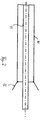
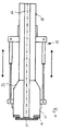
- Figures 1 to 7 show successive work stages in connection with the Installation of a device according to the invention.
- FIG. 1 shows a jacket tube 10 with a stainless steel tube 11 in front of it Assembly.
- the inner part, the stainless steel tube 11, is slightly above the end of the Jacket tube 10 addition.
- Figure 2 shows how a widening 12 has been welded to the casing tube 10.
- Figure 3 shows how a hydraulic device 20 in connection with the Assembly can be used.
- One part of a hydraulic ram is on the Exterior of the casing tube 10 attached.
- two extendable stamps are closed recognize that in turn with appropriate fasteners on the outer part a pusher 13 work together. These pushers have something larger diameter than the dimension of the expansion part 12 and are with a provided inward flange 14.
- the inner tube 11 is also provided with a flange 15.
- Figure 4 shows the state that occurs after the hydraulic ram of the pretensioner 20 are extended. In this position the parts 12 and 13 can be together be welded. After completing this process, the individual parts of the Pretensioner 20 are removed, and in this position is the desired one Preload between the casing tube 10 and the stainless steel tube 11 has been realized, because the flange 15 of the tube 11 abuts the flange 14 of the expansion part 13.
Landscapes
- Engineering & Computer Science (AREA)
- General Engineering & Computer Science (AREA)
- Mechanical Engineering (AREA)
- Rigid Pipes And Flexible Pipes (AREA)
Abstract
Description
Claims (4)
- Vorrichtung zum Transport von mehrphasigen Fluiden, insbesondere nassem Sauergas in einem Edelstahlrohr, das innerhalb eines Mantelrohres aus C-Stahl angeordnet ist, dadurch gekennzeichnet, dass das Edelstahlrohr (11, 111) drucktragend ausgebildet, elektrisch zum äußeren Mantelrohr (10, 110) isoliert sowie unter mechanischer Vorspannung zu diesem Mantelrohr gelagert ist.
- Vorrichtung nach Anspruch 1, dadurch gekennzeichnet, dass die an den Enden des Edelstahlrohres (10) angeschweißten Flansche (14) mit nach innen weisenden Flanschen in Erweiterungsstücken (12) des Mantelrohres (10) lösbar verbunden sind.
- Vorrichtung nach Anspruch 2, dadurch gekennzeichnet, dass die Befestigung der Flansche über Isolierhülsen und Isolierscheiben erfolgt.
- Vorrichtung nach Anspruch 2, dadurch gekennzeichnet, dass der entstehende Ringraum zwischen Mantel- und Innenrohr zur Verbesserung der Überwachung und Anlagensicherheit durch die Flanschverbindung(en) hindurch und somit auf ganzer Rohrleitungslänge spülbar ist.
Applications Claiming Priority (2)
| Application Number | Priority Date | Filing Date | Title |
|---|---|---|---|
| DE20219690U DE20219690U1 (de) | 2002-12-19 | 2002-12-19 | Vorrichtung zum Transport von mehrphasigen Fluiden |
| DE20219690U | 2002-12-19 |
Publications (2)
| Publication Number | Publication Date |
|---|---|
| EP1433989A1 true EP1433989A1 (de) | 2004-06-30 |
| EP1433989B1 EP1433989B1 (de) | 2007-01-10 |
Family
ID=32240645
Family Applications (1)
| Application Number | Title | Priority Date | Filing Date |
|---|---|---|---|
| EP20030028844 Expired - Lifetime EP1433989B1 (de) | 2002-12-19 | 2003-12-16 | Vorrichtung zum Transport von mehrphasigen Fluiden |
Country Status (2)
| Country | Link |
|---|---|
| EP (1) | EP1433989B1 (de) |
| DE (2) | DE20219690U1 (de) |
Families Citing this family (1)
| Publication number | Priority date | Publication date | Assignee | Title |
|---|---|---|---|---|
| EP4166831A1 (de) * | 2021-10-14 | 2023-04-19 | HABAU Hoch-u. Tiefbaugesellschaft m.b.H. | Rohrleitung zum transport von wasserstoff sowie rohrleitungssystem |
Citations (5)
| Publication number | Priority date | Publication date | Assignee | Title |
|---|---|---|---|---|
| DE1258215B (de) * | 1964-03-18 | 1968-01-04 | Winter & Co | Ummantelte Rohrleitung zur Foerderung von Gasen oder Fluessigkeiten und Verfahren zur Vorspannung eines Rohrleitungsabschnittes |
| US3865145A (en) * | 1973-05-10 | 1975-02-11 | Foundation Cryogenic Joint Ven | Pipeline system |
| GB2001407A (en) * | 1977-07-19 | 1979-01-31 | Arsenne R | Heat insulating pipe structure |
| US4219224A (en) * | 1978-04-06 | 1980-08-26 | Foundation Cryogenic Joint Venture | Cryogenic pipeline system |
| DE19709373A1 (de) * | 1997-03-07 | 1998-09-10 | Manfred Veenker | Leitung für gefährdende Fluide und Verfahren zu deren Herstellung |
-
2002
- 2002-12-19 DE DE20219690U patent/DE20219690U1/de not_active Expired - Lifetime
-
2003
- 2003-12-16 EP EP20030028844 patent/EP1433989B1/de not_active Expired - Lifetime
- 2003-12-16 DE DE50306251T patent/DE50306251D1/de not_active Expired - Lifetime
Patent Citations (5)
| Publication number | Priority date | Publication date | Assignee | Title |
|---|---|---|---|---|
| DE1258215B (de) * | 1964-03-18 | 1968-01-04 | Winter & Co | Ummantelte Rohrleitung zur Foerderung von Gasen oder Fluessigkeiten und Verfahren zur Vorspannung eines Rohrleitungsabschnittes |
| US3865145A (en) * | 1973-05-10 | 1975-02-11 | Foundation Cryogenic Joint Ven | Pipeline system |
| GB2001407A (en) * | 1977-07-19 | 1979-01-31 | Arsenne R | Heat insulating pipe structure |
| US4219224A (en) * | 1978-04-06 | 1980-08-26 | Foundation Cryogenic Joint Venture | Cryogenic pipeline system |
| DE19709373A1 (de) * | 1997-03-07 | 1998-09-10 | Manfred Veenker | Leitung für gefährdende Fluide und Verfahren zu deren Herstellung |
Also Published As
| Publication number | Publication date |
|---|---|
| DE20219690U1 (de) | 2004-04-29 |
| EP1433989B1 (de) | 2007-01-10 |
| DE50306251D1 (de) | 2007-02-22 |
Similar Documents
| Publication | Publication Date | Title |
|---|---|---|
| DE202012101837U1 (de) | Vorrichtung zum Verbinden von Doppelmantelrohren (zweiteiliges Rohrkupplungsteil) | |
| DE10355848A1 (de) | Flanschverbindung und Verfahren zu deren Herstellung | |
| EP3587110A2 (de) | Metallische rohrleitungsanordnung mit generativ hergestelltem anschlussteil | |
| DE1813260B2 (de) | Flanschverbindung fuer rohrfoermige teile unterschiedlicher waermeausdehnungskoeffizienten | |
| EP1433989B1 (de) | Vorrichtung zum Transport von mehrphasigen Fluiden | |
| DE7827573U1 (de) | Schalldämpfer für Luftleitungen, insbesondere für Klimaanlagen | |
| DE19516830A1 (de) | Preßwerkzeuge und Verfahren zum Verbinden von rohrförmigen Elementen | |
| EP0081667B1 (de) | Kompensatorfrei verlegbare Fernwärmeleitung | |
| EP0990101B2 (de) | Verfahren zum transport von sauergas | |
| DE102005003332B4 (de) | Magnetisch-induktives Durchflussmessgerät | |
| DE3814176C2 (de) | Doppelwandige Rohrleitung aus einer Vielzahl endseitig miteinander verbundener Rohrlängen | |
| DE3007509A1 (de) | Vorrichtung zum verbinden von zwei rohren | |
| EP0900352B1 (de) | Verfahren zur nachträglichen herstellung und revision von der hausanschlussseite für eine stichleitung mit einem vor- und rücklaufkanal zwischen einem einrohr-fernheizkanal und einem wärmeverbraucher | |
| DE3135983A1 (de) | "rohrleitungen zum transport von umweltgefaehrdenden medien sowie verfahren zur herstellung und verlegung derselben" | |
| DE3522693C2 (de) | ||
| DE4242236C1 (de) | Mauerdurchführung | |
| DD267640A3 (de) | Schallkompensator und verfahren zu seiner herstellung | |
| DE102012022975A1 (de) | Vorrichtung zur Abdichtung einer Undichtheit an einer fluidführenden Leitung; Verfahren zur Abdichtung einer Undichtheit an einer fluidführenden Leitung | |
| DE60216093T2 (de) | Rohrverbindung | |
| DE2364600A1 (de) | Kupplungsstueck fuer rohrfoermige, druckgasisolierte schaltanlagen | |
| DE3106160A1 (de) | Rohrpassstueck | |
| DE9414360U1 (de) | Rohrleitungssystem mit Überwachungseinrichtung zum Transport umweltgefährdeter Medien, insbesondere für Heizöle | |
| DE2545518A1 (de) | Rohrklemm- und dichtungskupplung fuer unterwasser-pipelines | |
| DE2426730C3 (de) | Rohrschelle für den Anschluß von Rohrstutzen an Rohrleitungen | |
| DE2949534A1 (de) | Rohrverbindung |
Legal Events
| Date | Code | Title | Description |
|---|---|---|---|
| PUAI | Public reference made under article 153(3) epc to a published international application that has entered the european phase |
Free format text: ORIGINAL CODE: 0009012 |
|
| AK | Designated contracting states |
Kind code of ref document: A1 Designated state(s): AT BE BG CH CY CZ DE DK EE ES FI FR GB GR HU IE IT LI LU MC NL PT RO SE SI SK TR |
|
| AX | Request for extension of the european patent |
Extension state: AL LT LV MK |
|
| RAP1 | Party data changed (applicant data changed or rights of an application transferred) |
Owner name: PPS PIPELINE SYSTEMS GMBH WINTER ROHRBAU Owner name: EXXONMOBIL PRODUCTION DEUTSCHLAND GBMH |
|
| 17P | Request for examination filed |
Effective date: 20041223 |
|
| AKX | Designation fees paid |
Designated state(s): DE |
|
| 17Q | First examination report despatched |
Effective date: 20050411 |
|
| GRAP | Despatch of communication of intention to grant a patent |
Free format text: ORIGINAL CODE: EPIDOSNIGR1 |
|
| GRAS | Grant fee paid |
Free format text: ORIGINAL CODE: EPIDOSNIGR3 |
|
| GRAA | (expected) grant |
Free format text: ORIGINAL CODE: 0009210 |
|
| AK | Designated contracting states |
Kind code of ref document: B1 Designated state(s): DE |
|
| REF | Corresponds to: |
Ref document number: 50306251 Country of ref document: DE Date of ref document: 20070222 Kind code of ref document: P |
|
| PLBE | No opposition filed within time limit |
Free format text: ORIGINAL CODE: 0009261 |
|
| STAA | Information on the status of an ep patent application or granted ep patent |
Free format text: STATUS: NO OPPOSITION FILED WITHIN TIME LIMIT |
|
| 26N | No opposition filed |
Effective date: 20071011 |
|
| PGFP | Annual fee paid to national office [announced via postgrant information from national office to epo] |
Ref country code: DE Payment date: 20211217 Year of fee payment: 19 |
|
| REG | Reference to a national code |
Ref country code: DE Ref legal event code: R119 Ref document number: 50306251 Country of ref document: DE |
|
| PG25 | Lapsed in a contracting state [announced via postgrant information from national office to epo] |
Ref country code: DE Free format text: LAPSE BECAUSE OF NON-PAYMENT OF DUE FEES Effective date: 20230701 |