EP1434070A1 - Optische Monomodefaser mit optimierter chromatische Dispersion - Google Patents
Optische Monomodefaser mit optimierter chromatische Dispersion Download PDFInfo
- Publication number
- EP1434070A1 EP1434070A1 EP03293180A EP03293180A EP1434070A1 EP 1434070 A1 EP1434070 A1 EP 1434070A1 EP 03293180 A EP03293180 A EP 03293180A EP 03293180 A EP03293180 A EP 03293180A EP 1434070 A1 EP1434070 A1 EP 1434070A1
- Authority
- EP
- European Patent Office
- Prior art keywords
- index
- optical fiber
- wavelength
- chromatic dispersion
- less
- Prior art date
- Legal status (The legal status is an assumption and is not a legal conclusion. Google has not performed a legal analysis and makes no representation as to the accuracy of the status listed.)
- Granted
Links
- 239000013307 optical fiber Substances 0.000 title claims abstract description 105
- 239000006185 dispersion Substances 0.000 title claims abstract description 72
- 230000005540 biological transmission Effects 0.000 claims description 23
- 238000005253 cladding Methods 0.000 claims description 11
- 239000000835 fiber Substances 0.000 description 15
- 238000005452 bending Methods 0.000 description 5
- 230000000052 comparative effect Effects 0.000 description 5
- 230000009022 nonlinear effect Effects 0.000 description 5
- 230000000593 degrading effect Effects 0.000 description 3
- 238000004519 manufacturing process Methods 0.000 description 3
- 230000003287 optical effect Effects 0.000 description 3
- 230000035945 sensitivity Effects 0.000 description 2
- 230000003595 spectral effect Effects 0.000 description 2
- 229920000297 Rayon Polymers 0.000 description 1
- 238000009933 burial Methods 0.000 description 1
- 230000015556 catabolic process Effects 0.000 description 1
- 238000006731 degradation reaction Methods 0.000 description 1
- 230000000694 effects Effects 0.000 description 1
- 230000009021 linear effect Effects 0.000 description 1
- NJPPVKZQTLUDBO-UHFFFAOYSA-N novaluron Chemical compound C1=C(Cl)C(OC(F)(F)C(OC(F)(F)F)F)=CC=C1NC(=O)NC(=O)C1=C(F)C=CC=C1F NJPPVKZQTLUDBO-UHFFFAOYSA-N 0.000 description 1
- 239000002964 rayon Substances 0.000 description 1
- 230000008685 targeting Effects 0.000 description 1
- 230000007704 transition Effects 0.000 description 1
Images


Classifications
-
- G—PHYSICS
- G02—OPTICS
- G02B—OPTICAL ELEMENTS, SYSTEMS OR APPARATUS
- G02B6/00—Light guides; Structural details of arrangements comprising light guides and other optical elements, e.g. couplings
- G02B6/02—Optical fibres with cladding with or without a coating
- G02B6/02004—Optical fibres with cladding with or without a coating characterised by the core effective area or mode field radius
- G02B6/02009—Large effective area or mode field radius, e.g. to reduce nonlinear effects in single mode fibres
-
- G—PHYSICS
- G02—OPTICS
- G02B—OPTICAL ELEMENTS, SYSTEMS OR APPARATUS
- G02B6/00—Light guides; Structural details of arrangements comprising light guides and other optical elements, e.g. couplings
- G02B6/02—Optical fibres with cladding with or without a coating
- G02B6/02214—Optical fibres with cladding with or without a coating tailored to obtain the desired dispersion, e.g. dispersion shifted, dispersion flattened
- G02B6/02219—Characterised by the wavelength dispersion properties in the silica low loss window around 1550 nm, i.e. S, C, L and U bands from 1460-1675 nm
- G02B6/02228—Dispersion flattened fibres, i.e. having a low dispersion variation over an extended wavelength range
- G02B6/02238—Low dispersion slope fibres
- G02B6/02242—Low dispersion slope fibres having a dispersion slope <0.06 ps/km/nm2
-
- G—PHYSICS
- G02—OPTICS
- G02B—OPTICAL ELEMENTS, SYSTEMS OR APPARATUS
- G02B6/00—Light guides; Structural details of arrangements comprising light guides and other optical elements, e.g. couplings
- G02B6/02—Optical fibres with cladding with or without a coating
- G02B6/02214—Optical fibres with cladding with or without a coating tailored to obtain the desired dispersion, e.g. dispersion shifted, dispersion flattened
- G02B6/02219—Characterised by the wavelength dispersion properties in the silica low loss window around 1550 nm, i.e. S, C, L and U bands from 1460-1675 nm
- G02B6/02266—Positive dispersion fibres at 1550 nm
- G02B6/02271—Non-zero dispersion shifted fibres, i.e. having a small positive dispersion at 1550 nm, e.g. ITU-T G.655 dispersion between 1.0 to 10 ps/nm.km for avoiding nonlinear effects
-
- G—PHYSICS
- G02—OPTICS
- G02B—OPTICAL ELEMENTS, SYSTEMS OR APPARATUS
- G02B6/00—Light guides; Structural details of arrangements comprising light guides and other optical elements, e.g. couplings
- G02B6/02—Optical fibres with cladding with or without a coating
- G02B6/036—Optical fibres with cladding with or without a coating core or cladding comprising multiple layers
- G02B6/03616—Optical fibres characterised both by the number of different refractive index layers around the central core segment, i.e. around the innermost high index core layer, and their relative refractive index difference
- G02B6/03638—Optical fibres characterised both by the number of different refractive index layers around the central core segment, i.e. around the innermost high index core layer, and their relative refractive index difference having 3 layers only
- G02B6/03644—Optical fibres characterised both by the number of different refractive index layers around the central core segment, i.e. around the innermost high index core layer, and their relative refractive index difference having 3 layers only arranged - + -
-
- G—PHYSICS
- G02—OPTICS
- G02B—OPTICAL ELEMENTS, SYSTEMS OR APPARATUS
- G02B6/00—Light guides; Structural details of arrangements comprising light guides and other optical elements, e.g. couplings
- G02B6/02—Optical fibres with cladding with or without a coating
- G02B6/036—Optical fibres with cladding with or without a coating core or cladding comprising multiple layers
- G02B6/03616—Optical fibres characterised both by the number of different refractive index layers around the central core segment, i.e. around the innermost high index core layer, and their relative refractive index difference
- G02B6/03661—Optical fibres characterised both by the number of different refractive index layers around the central core segment, i.e. around the innermost high index core layer, and their relative refractive index difference having 4 layers only
- G02B6/03666—Optical fibres characterised both by the number of different refractive index layers around the central core segment, i.e. around the innermost high index core layer, and their relative refractive index difference having 4 layers only arranged - + - +
-
- H—ELECTRICITY
- H04—ELECTRIC COMMUNICATION TECHNIQUE
- H04B—TRANSMISSION
- H04B10/00—Transmission systems employing electromagnetic waves other than radio-waves, e.g. infrared, visible or ultraviolet light, or employing corpuscular radiation, e.g. quantum communication
- H04B10/25—Arrangements specific to fibre transmission
- H04B10/2507—Arrangements specific to fibre transmission for the reduction or elimination of distortion or dispersion
- H04B10/2513—Arrangements specific to fibre transmission for the reduction or elimination of distortion or dispersion due to chromatic dispersion
- H04B10/2525—Arrangements specific to fibre transmission for the reduction or elimination of distortion or dispersion due to chromatic dispersion using dispersion-compensating fibres
- H04B10/25253—Arrangements specific to fibre transmission for the reduction or elimination of distortion or dispersion due to chromatic dispersion using dispersion-compensating fibres with dispersion management, i.e. using a combination of different kind of fibres in the transmission system
-
- G—PHYSICS
- G02—OPTICS
- G02B—OPTICAL ELEMENTS, SYSTEMS OR APPARATUS
- G02B6/00—Light guides; Structural details of arrangements comprising light guides and other optical elements, e.g. couplings
- G02B6/02—Optical fibres with cladding with or without a coating
- G02B6/02004—Optical fibres with cladding with or without a coating characterised by the core effective area or mode field radius
Definitions
- the invention relates to the field of optical fibers for networks of wavelength division multiplex transmission (WDM).
- WDM wavelength division multiplex transmission
- Networks of WDM transmission targeted are more particularly the so-called networks "Metropolitan”.
- Metropolitan networks concern lengths of transmission typically between a few kilometers, for example 10km, and about 300km.
- the invention aims to obtain an optical fiber representing a very good compromise for this type of network.
- This compromise mainly incorporates, for the distance considered, constraints of non-linear effect leading to distortion in the conveyed signal, constraints of signal loss attenuating the conveyed signal, and constraints of the cost of producing the optical fiber considered and of the overall transmission system.
- the invention aims to obtain a relatively simple and inexpensive optical fiber to produce, having a high effective surface area, typically greater than 50 ⁇ m 2 at the wavelength of 1550nm, thus making it possible to reduce the impact.
- the invention also targeting 'Obtaining an optical fiber which is single mode on the S, C and L bands, and which offers good resistance to non-linear effects on these spectral bands.
- the invention also aims to obtain an optical fiber which can be used in a transmission system even in the absence of any means for compensating for the chromatic dispersion of said optical fiber.
- the chromatic dispersion must remain at the same time sufficiently low as not to require dispersion compensation chromatic and high enough not to induce non-linear effects significantly degrading the transmission.
- the invention aims to obtain an optical fiber which is simple and inexpensive to produce, having an effective surface greater than 50 ⁇ m 2 at the wavelength of 1550nm, and a dispersion of between 2 and 9ps / nm.km over a wavelength range from 1460nm to 1625nm, as well as acceptable bending losses.
- Acceptable bending losses advantageously remain less than 100dB / m for a diameter of 20mm at a wavelength equal to 1625nm or even advantageously less than 30dB / m for a diameter of 20mm at a wavelength equal to 1550nm.
- the invention therefore aims to obtain an optical fiber which is monomode and usable over a wide spectral band, while minimizing non-linear effects and while not necessarily requiring means of compensation for chromatic dispersion when used in a metropolitan network, having also acceptable bending losses.
- the optical fiber according to the invention has an optimized narrow range of chromatic dispersion, thus than a maximum threshold for chromatic dispersion slope and a maximum threshold ratio between the chromatic dispersion and the chromatic dispersion slope, as well as one or two sufficiently buried sheaths.
- the optical fibers comprise a core with a variable index profile and a sheath with constant index.
- the heart has several slices which can have different possible shapes, in particular a rectangular, triangular shape, trapezoidal or alpha, be otherwise truncated and / or have a pedestal.
- the invention aims to obtain an optical fiber that is simple and inexpensive to produce.
- the optical fiber according to the invention will be limited to three or four sections.
- the three-slice profile is the simplest structurally, but it requires burial much the only slice buried while the four-slice profile structurally less simple allows either to bury less each of the two buried slices retaining an equivalent effective surface area of keep very buried slices by increasing the effective surface.
- the central edge is raised, unlike coaxial profiles which have a extended central hollow.
- the chromatic dispersion slope does not should not be chosen too weak because otherwise the optical fiber becomes too expensive to achieve.
- the minimum dispersion slope threshold chosen is an important aspect of the invention which opens the way to obtaining the compromise sought which without it turns out to be too difficult to obtain. A little more preferential minimum threshold higher than the previous one makes it easier to obtain an optical fiber according to the invention having optical properties comparable to that obtained by remaining close to the lowest minimum threshold.
- the claimed narrow range of chromatic dispersion, the narrow range claimed chromatic dispersion slope, the character sufficiently buried from the buried section or buried sections relative to the height of the central section, the maximum threshold of zero dispersion wavelength, as well as the limited number of sections, constitute the essential characteristics of the invention allowing the obtaining of the good compromise which is sought for the optical fiber mainly intended for use in a system of metropolitan transmission.
- Other preferential optional features further improve said good compromise to go towards a very good even an excellent compromise.
- a fiber is known optics which notably has the drawback of a dispersion slope chromatic too high and buried slices insufficiently buried for obtain the compromise sought.
- an optical fiber which has the particular disadvantage of a chromatic dispersion slope too high and buried slices insufficiently buried to obtain the compromise sought.
- an optical fiber is known which has the disadvantage of too little chromatic dispersion and buried slices insufficiently buried to obtain the compromise research.
- a fiber is known optics which notably has the drawback of a dispersion slope chromatic too weak; furthermore, no profile is specified.
- a fiber is known optics which notably has the drawback of a dispersion slope too high chromaticity, too low chromatic dispersion and slices buried insufficiently buried to obtain the desired compromise.
- an optical fiber for a transmission network with wavelength multiplexing, successively comprising from the center to the periphery a core having a profile of variable index then a sheath of constant index, the variable index profile of the core being successively constituted, from the center towards the periphery, of a central section of maximum index greater than the index of the sheath, of a section buried with a minimum index lower than the cladding index, with an annular section of maximum index higher than the cladding index and lower than the maximum index of the central section, the ratio between the absolute value of the minimum index of the buried section and the maximum index of the central section being greater than 50%, the index of the central section being worth at least 70% of the maximum index of the central section in at least one place located to less s 1 ⁇ m from the center of the optical fiber, the radii and indices of each of the slices being determined so that the optical fiber has, on the one hand at the wavelength of 1550nm, first
- the ratio between the absolute value of the minimum index of the buried section and the maximum index of the section central is preferably between 60% and 90%.
- an optical fiber for a transmission network with wavelength multiplexing, successively comprising from the center to the periphery a core having a profile of variable index then a sheath of constant index, the variable index profile of the core successively consisting, from the center towards the periphery, of a central slice of maximum index greater than the index of the sheath, of a first buried slice with minimum index lower than the cladding index, with an annular slice with maximum index greater than the cladding index and less than the maximum index with the central slice, with a second buried slice minimum index lower than the cladding index, the ratio between on the one hand the absolute value of the sum of the minimum index of the first buried section and the minimum index of the second buried section and other p art the maximum index of the central section being greater than 50%, the index of the central section being worth at least 70% of the maximum index of the central section in at least one place situated less than 1 ⁇ m from the center of the optical fiber,
- the ratio between the absolute value of the minimum index of the first buried tranche and the maximum index of the central section is preferably between 40% and 90%.
- the cable cut wavelength, commonly denoted ⁇ cc of the optical fiber obtained, is chosen to be less than 1450nm so as to be able to be single mode in S, C and L bands
- the maximum index of the annular section preferably remains below 3.10 -3 .
- the radii and the indices of each slice are determined so that the optical fiber has a cable cut wavelength less than 1260nm.
- the invention also relates in this preferred embodiment to the association on the one hand of a metropolitan transmission network over a distance of less than 350 km and on the other hand of an access network, comprising respectively optical fibers of transmission and access optical fibers, at least some of the transmission optical fibers of which at least some of the access optical fibers are optical fibers whose cable cut wavelength is less than 1260nm.
- all the transmission optical fibers and all the access optical fibers are optical fibers whose cable cut-off wavelength is less than 1260 nm.
- the radii and the indices of each of the sections are preferably determined so that the optical fiber has, at the length of 1550nm wave, a chromatic dispersion slope between 0.025ps / nm 2 .km and 0.035ps / nm 2 .km.
- the radii and the indices of each of the slices are determined so that the optical fiber has, at the wavelength of 1550nm, a chromatic dispersion of between 4.5ps / nm.km and 5.5ps /nm.km.
- the radii and the indices of each of the slices are determined from so that the optical fiber has, at the wavelength of 1460nm, chromatic dispersion greater than 2ps / nm.km.
- the radii and the indices of each of the slices are determined so that the optical fiber has a wavelength of zero dispersion between 1375nm and 1415nm, so as to obtain a dispersion in the vicinity of 5ps / nm.km and a dispersion slope in the vicinity of 0.03ps / nm 2 .km.
- no wafer has several trays of index value as a function of radius, i.e. if the slices can have various forms, no section is in staircase with several steps. Of preferably all the slices each have only one tray, the transitions between trays that can however be tilted, i.e. not be vertical.
- the invention also relates to a transmission system on a distance less than 350km, comprising at least one optical fiber according to the invention and not comprising dispersion compensation means chromatic of said optical fiber.
- the usual means of compensation for chromatic dispersion include optical fibers with compensation for chromatic dispersion, whether in module or cable, they can also come in the form of optical components.
- the optical fiber according to the invention is used in length greater than 1 km. In the case where the optical fiber according to the invention would still be used with compensation means, for example an optical fiber with compensation for dispersion, it would take only a small length of this optical fiber to dispersion compensation to effectively compensate for dispersion of the optical fiber according to the invention.
- Figure 1 schematically shows an example of the type of profile to four slices of an optical fiber according to the invention.
- the first tranche called central section has a maximum difference in index ⁇ n1 with the index sheath constant and an outside radius r1.
- the maximum index difference ⁇ n1 is positive.
- the index is constant.
- the second tranche called the first buried tranche has a difference maximum index ⁇ n2 with the constant cladding index and an outside radius r2.
- the maximum index difference ⁇ n2 is negative.
- the third tranche called tranche ring has a maximum difference in index ⁇ n3 with the constant index of the sheath and an outer radius r3.
- the maximum index difference ⁇ n3 is positive.
- the index is constant.
- the fourth section called second buried section has a maximum difference of index ⁇ n4 with the constant index of the sheath and an external radius r4.
- the maximum index difference ⁇ n4 is negative.
- the index is constant. Beyond the radius r4 is the index sheath constant.
- the second buried section does not exist and the first section buried is simply called buried slice.
- FIG. 2 represents a table comprising the values of radii and differences in index for fifteen examples noted Ex of profiles with three or four slices of an optical fiber according to the invention.
- the left column includes the names of examples 1 to 19.
- the three or four columns following express in ⁇ m the radii of the core index profile.
- the next three or four columns express index differences a thousand times (without unit).
- the next column expresses the relationship between on the one hand the value absolute of the minimum index of the buried section or the first section buried if there are two and on the other hand the maximum index of the central section.
- the next column expresses the ratio between on the one hand the absolute value of the minimum index of the second buried tranche when there is one and the other share the maximum index of the central tranche.
- the next column expresses the ratio between on the one hand the absolute value of the sum of the minimum index of the first buried tranche and the minimum index of the second buried tranche and on the other hand the maximum index of the central tranche.
- FIG. 3 represents a table comprising certain characteristics of the optical fiber profiles according to the invention defined in FIG. 2.
- the left column includes the names of the examples from No. 1 to No. 15. For each example considered, the other columns represent characteristics of the optical fiber corresponding to the example considered.
- the next column represents the theoretical cut length ⁇ cth expressed in nm.
- the next column represents the effective cut-off length ⁇ ceff expressed in nm.
- the next column represents a maximum threshold for cable cut-off wavelength ⁇ cc expressed in nm.
- the cable cutoff wavelength and the effective cutoff wavelength are defined in standard ITU G 650.
- the following three columns represent the chromatic dispersion C expressed in ps / nm.km, at wavelengths 1460nm, 1550nm and 1625nm respectively.
- the next column represents the chromatic dispersion slope C 'expressed in ps / nm 2 .km at a wavelength equal to 1550nm.
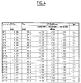
- FIG. 4 represents a table comprising other characteristics of the optical fiber profiles according to the invention defined in FIG. 2.
- the left column comprises the names of the examples from No. 1 to No. 19.
- the other columns represent characteristics of the optical fiber corresponding to the example considered.
- the next column represents the 2W 02 mode diameter expressed in ⁇ m at the wavelength of 1550nm.
- the next column represents the effective area S eff expressed in ⁇ m 2 at the wavelength of 1550nm.
- the next three columns represent the maximum bending loss thresholds expressed in dB / m, when the optical fiber is wound on a diameter of 20mm, respectively at the wavelengths of 1550nm, 1625nm and 1675nm.
- the optical fibers according to the invention would remain usable in the U band extending from 1625nm to 1675nm.
- the last column represents the sensitivity to microbends, at a wavelength of 1550 nm, given in proportion with respect to the G652 fiber marketed by the applicant under this reference.
- the three-slice examples n ° 1 to n ° 6 and n ° 19 show on average losses by curvature and micro-curvature at a wavelength of 1550nm which are weaker and therefore better than those of the examples with four slices n ° 7 at # 18.
- the examples with four sections n ° 7 to n ° 18 have on average an effective surface at 1550nm which is higher and therefore better than that of the examples with three sections n ° 1 to n ° 6 and n ° 19.
Landscapes
- Physics & Mathematics (AREA)
- Dispersion Chemistry (AREA)
- Chemical & Material Sciences (AREA)
- General Physics & Mathematics (AREA)
- Optics & Photonics (AREA)
- Signal Processing (AREA)
- Computer Networks & Wireless Communication (AREA)
- Engineering & Computer Science (AREA)
- Electromagnetism (AREA)
- Optical Communication System (AREA)
- Optical Fibers, Optical Fiber Cores, And Optical Fiber Bundles (AREA)
- Light Guides In General And Applications Therefor (AREA)
- Glass Compositions (AREA)
Priority Applications (1)
| Application Number | Priority Date | Filing Date | Title |
|---|---|---|---|
| EP06075281A EP1655626B1 (de) | 2002-12-24 | 2003-12-16 | Optische Monomodefaser mit optimierter chromatische Dispersion |
Applications Claiming Priority (2)
| Application Number | Priority Date | Filing Date | Title |
|---|---|---|---|
| FR0216614A FR2849213B1 (fr) | 2002-12-24 | 2002-12-24 | Fibre optique |
| FR0216614 | 2002-12-24 |
Related Child Applications (1)
| Application Number | Title | Priority Date | Filing Date |
|---|---|---|---|
| EP06075281A Division EP1655626B1 (de) | 2002-12-24 | 2003-12-16 | Optische Monomodefaser mit optimierter chromatische Dispersion |
Publications (2)
| Publication Number | Publication Date |
|---|---|
| EP1434070A1 true EP1434070A1 (de) | 2004-06-30 |
| EP1434070B1 EP1434070B1 (de) | 2006-05-10 |
Family
ID=32406481
Family Applications (2)
| Application Number | Title | Priority Date | Filing Date |
|---|---|---|---|
| EP03293180A Expired - Lifetime EP1434070B1 (de) | 2002-12-24 | 2003-12-16 | Optische Monomodefaser mit optimierter chromatische Dispersion |
| EP06075281A Expired - Lifetime EP1655626B1 (de) | 2002-12-24 | 2003-12-16 | Optische Monomodefaser mit optimierter chromatische Dispersion |
Family Applications After (1)
| Application Number | Title | Priority Date | Filing Date |
|---|---|---|---|
| EP06075281A Expired - Lifetime EP1655626B1 (de) | 2002-12-24 | 2003-12-16 | Optische Monomodefaser mit optimierter chromatische Dispersion |
Country Status (8)
| Country | Link |
|---|---|
| US (1) | US6895153B2 (de) |
| EP (2) | EP1434070B1 (de) |
| JP (1) | JP4410547B2 (de) |
| CN (1) | CN100395570C (de) |
| AT (2) | ATE407375T1 (de) |
| DE (2) | DE60305140T2 (de) |
| DK (2) | DK1434070T3 (de) |
| FR (1) | FR2849213B1 (de) |
Families Citing this family (6)
| Publication number | Priority date | Publication date | Assignee | Title |
|---|---|---|---|---|
| NL1020780C2 (nl) * | 2002-06-06 | 2004-01-06 | Draka Fibre Technology Bv | Single mode optische vezel, alsmede optisch communicatiesysteem. |
| FR2849214B1 (fr) * | 2002-12-24 | 2005-03-04 | Cit Alcatel | Fibre optique a compensation de dispersion chromatique dans la bande s |
| FR2871899B1 (fr) * | 2004-06-22 | 2006-09-15 | Alcatel Sa | Fibre optique a compensation de dispersion chromatique |
| FR2899693B1 (fr) * | 2006-04-10 | 2008-08-22 | Draka Comteq France | Fibre optique monomode. |
| US7437045B2 (en) * | 2006-05-02 | 2008-10-14 | Sterlite Technologies Limited | Dispersion optimized optical fiber for wideband optical transmission |
| CN110749953B (zh) * | 2019-10-29 | 2023-07-14 | 长飞光纤光缆股份有限公司 | 一种低色散单模光纤 |
Citations (6)
| Publication number | Priority date | Publication date | Assignee | Title |
|---|---|---|---|---|
| EP1018656A1 (de) * | 1999-01-04 | 2000-07-12 | Alcatel | Optische Faser mit geringem Gradienten der chromatischen Dispersion |
| EP1103830A1 (de) * | 1999-11-25 | 2001-05-30 | Alcatel | Dispersionsverschobene optische Faser für ein faseroptisches Wellenlängenmultiplexübertragungssystem |
| EP1211533A2 (de) * | 2000-11-28 | 2002-06-05 | The Furukawa Electric Co., Ltd. | Optische Faser und diese verwendendes optisches Übertragungssystem |
| EP1279648A2 (de) * | 2001-07-26 | 2003-01-29 | Fujikura Ltd. | Optische Faser und Vorform sowie Verfahren zum Herstellen der Vorform der optischen Faser |
| EP1288685A1 (de) * | 2001-08-27 | 2003-03-05 | Alcatel | Optische Faser für ein Wellenlängenmultiplexübertragungssystem |
| EP1291688A2 (de) * | 2001-08-29 | 2003-03-12 | Sumitomo Electric Industries, Ltd. | Optische Übertragungsleitung und optisches Übertragungssystem |
Family Cites Families (3)
| Publication number | Priority date | Publication date | Assignee | Title |
|---|---|---|---|---|
| US5905838A (en) | 1998-02-18 | 1999-05-18 | Lucent Technologies Inc. | Dual window WDM optical fiber communication |
| US6535676B1 (en) * | 1998-09-17 | 2003-03-18 | Alcatel | Optical fibre with optimized ratio of effective area to dispersion scope for optical fibre transmission system with wavelength multiplexing |
| CN1231775C (zh) * | 1998-12-18 | 2005-12-14 | 皮雷利·卡维系统有限公司 | 城域或接入光通信系统以及用于该系统的光纤和传输方法 |
-
2002
- 2002-12-24 FR FR0216614A patent/FR2849213B1/fr not_active Expired - Fee Related
-
2003
- 2003-12-16 DK DK03293180T patent/DK1434070T3/da active
- 2003-12-16 DE DE60305140T patent/DE60305140T2/de not_active Expired - Lifetime
- 2003-12-16 DK DK06075281T patent/DK1655626T3/da active
- 2003-12-16 AT AT06075281T patent/ATE407375T1/de not_active IP Right Cessation
- 2003-12-16 DE DE60323408T patent/DE60323408D1/de not_active Expired - Lifetime
- 2003-12-16 EP EP03293180A patent/EP1434070B1/de not_active Expired - Lifetime
- 2003-12-16 AT AT03293180T patent/ATE326019T1/de not_active IP Right Cessation
- 2003-12-16 EP EP06075281A patent/EP1655626B1/de not_active Expired - Lifetime
- 2003-12-19 JP JP2003422216A patent/JP4410547B2/ja not_active Expired - Fee Related
- 2003-12-22 US US10/740,456 patent/US6895153B2/en not_active Expired - Lifetime
- 2003-12-23 CN CNB2003101230657A patent/CN100395570C/zh not_active Expired - Fee Related
Patent Citations (6)
| Publication number | Priority date | Publication date | Assignee | Title |
|---|---|---|---|---|
| EP1018656A1 (de) * | 1999-01-04 | 2000-07-12 | Alcatel | Optische Faser mit geringem Gradienten der chromatischen Dispersion |
| EP1103830A1 (de) * | 1999-11-25 | 2001-05-30 | Alcatel | Dispersionsverschobene optische Faser für ein faseroptisches Wellenlängenmultiplexübertragungssystem |
| EP1211533A2 (de) * | 2000-11-28 | 2002-06-05 | The Furukawa Electric Co., Ltd. | Optische Faser und diese verwendendes optisches Übertragungssystem |
| EP1279648A2 (de) * | 2001-07-26 | 2003-01-29 | Fujikura Ltd. | Optische Faser und Vorform sowie Verfahren zum Herstellen der Vorform der optischen Faser |
| EP1288685A1 (de) * | 2001-08-27 | 2003-03-05 | Alcatel | Optische Faser für ein Wellenlängenmultiplexübertragungssystem |
| EP1291688A2 (de) * | 2001-08-29 | 2003-03-12 | Sumitomo Electric Industries, Ltd. | Optische Übertragungsleitung und optisches Übertragungssystem |
Non-Patent Citations (1)
| Title |
|---|
| LIU Y ET AL: "DESIGN AND FABRICATION OF LOCALLY DISPERSION-FLATTENED LARGE EFFECTIVE AREA FIBERS", PROCEEDINGS OF THE EUROPEAN CONFERENCE ON OPTICAL COMMUNICATION, XX, XX, vol. 1, 20 September 1998 (1998-09-20), pages 37 - 38, XP000879650 * |
Also Published As
| Publication number | Publication date |
|---|---|
| CN100395570C (zh) | 2008-06-18 |
| JP2004206118A (ja) | 2004-07-22 |
| EP1434070B1 (de) | 2006-05-10 |
| ATE326019T1 (de) | 2006-06-15 |
| US6895153B2 (en) | 2005-05-17 |
| EP1655626B1 (de) | 2008-09-03 |
| DK1655626T3 (da) | 2008-12-08 |
| FR2849213A1 (fr) | 2004-06-25 |
| FR2849213B1 (fr) | 2005-03-04 |
| DE60323408D1 (de) | 2008-10-16 |
| JP4410547B2 (ja) | 2010-02-03 |
| US20040131323A1 (en) | 2004-07-08 |
| DE60305140D1 (de) | 2006-06-14 |
| DE60305140T2 (de) | 2007-03-01 |
| DK1434070T3 (da) | 2006-06-12 |
| ATE407375T1 (de) | 2008-09-15 |
| EP1655626A1 (de) | 2006-05-10 |
| CN1510443A (zh) | 2004-07-07 |
Similar Documents
| Publication | Publication Date | Title |
|---|---|---|
| EP1030199B1 (de) | Optische Faser für Wellenlängenmultiplex-Übertragungssysteme | |
| FR2795828A1 (fr) | Fibre optique pour la compensation de la dispersion chromatique d'une fibre optique a dispersion chromatique positive | |
| EP1046069A1 (de) | Optischer faser mit optimalem verhältnis zwischen effektiven flächen und dispersionsgradienten für faseroptische wellenlängemultiplexübertragungssystemen | |
| EP1288685A1 (de) | Optische Faser für ein Wellenlängenmultiplexübertragungssystem | |
| EP0987568B1 (de) | Optimierte dispersionsverschobene monomodige optische Faser für hohe Datenraten | |
| EP1004905B1 (de) | Dispersionskompensierende Faser für ein faseroptisches Wellenlängenmultiplexübertragungssystem mit eine Dispersionsverschobene Faserstrecke | |
| EP1081514B1 (de) | Optische Faser zur Kompensation der chromatischen Dispersion einer optischen Faser mit positiver chromatischer Dispersion | |
| WO2000020905A1 (fr) | Fibre optique monomode a dispersion decalee a grande aire effective | |
| EP1351417B1 (de) | Dispersionskompensationsfaser unter Verwendung von Moden höherer Ordnung | |
| EP1434070B1 (de) | Optische Monomodefaser mit optimierter chromatische Dispersion | |
| FR2864254A1 (fr) | Fibre optique multimode hom a gestion de dispersion | |
| EP1018656A1 (de) | Optische Faser mit geringem Gradienten der chromatischen Dispersion | |
| EP1382981A1 (de) | Optische Faser mit Dispersionsverwaltung | |
| EP1213595B1 (de) | Kompensation der chromatischen Dispersion in einem Glasfaserübertragungssystem und Kompensationsglasfaser | |
| EP1030200B1 (de) | Optische Faser mit grosser effektiver Fläche und starker chromatischer Dispersion | |
| EP1434071B1 (de) | Optische Faser zur Kompensierung der chromatischen Dispersion im S-Band | |
| FR2871899A1 (fr) | Fibre optique a compensation de dispersion chromatique | |
| EP1103830A1 (de) | Dispersionsverschobene optische Faser für ein faseroptisches Wellenlängenmultiplexübertragungssystem | |
| EP1327898A1 (de) | Glasfaser mit einer komplexen Brechungsindexstruktur in Ringform | |
| EP1549978B1 (de) | Optische faser mit kompensation der chromatischen dispersion | |
| EP1288682B1 (de) | Optische Faser für Wellenlängenmultiplex-Übertragungssystem | |
| FR2867865A1 (fr) | Fibre optique a compensation de dispersion chromatique en bande utilisant un mode d'ordre superieur | |
| EP1018812A1 (de) | Faseroptisches WDM Übertragungssystem mit Farbzerstreuungskompensation |
Legal Events
| Date | Code | Title | Description |
|---|---|---|---|
| PUAI | Public reference made under article 153(3) epc to a published international application that has entered the european phase |
Free format text: ORIGINAL CODE: 0009012 |
|
| AK | Designated contracting states |
Kind code of ref document: A1 Designated state(s): AT BE BG CH CY CZ DE DK EE ES FI FR GB GR HU IE IT LI LU MC NL PT RO SE SI SK TR |
|
| AX | Request for extension of the european patent |
Extension state: AL LT LV MK |
|
| 17P | Request for examination filed |
Effective date: 20040915 |
|
| 17Q | First examination report despatched |
Effective date: 20050114 |
|
| RAP1 | Party data changed (applicant data changed or rights of an application transferred) |
Owner name: DRAKA COMTEQ B.V. |
|
| AKX | Designation fees paid |
Designated state(s): AT BE BG CH CY CZ DE DK EE ES FI FR GB GR HU IE IT LI LU MC NL PT RO SE SI SK TR |
|
| GRAP | Despatch of communication of intention to grant a patent |
Free format text: ORIGINAL CODE: EPIDOSNIGR1 |
|
| GRAS | Grant fee paid |
Free format text: ORIGINAL CODE: EPIDOSNIGR3 |
|
| GRAA | (expected) grant |
Free format text: ORIGINAL CODE: 0009210 |
|
| RAP1 | Party data changed (applicant data changed or rights of an application transferred) |
Owner name: DRAKA COMTEQ B.V. |
|
| RIC1 | Information provided on ipc code assigned before grant |
Ipc: G02B 6/036 20060101ALI20060315BHEP Ipc: H04B 10/18 20060101ALI20060315BHEP Ipc: G02B 6/02 20060101AFI20060315BHEP |
|
| AK | Designated contracting states |
Kind code of ref document: B1 Designated state(s): AT BE BG CH CY CZ DE DK EE ES FI FR GB GR HU IE IT LI LU MC NL PT RO SE SI SK TR |
|
| PG25 | Lapsed in a contracting state [announced via postgrant information from national office to epo] |
Ref country code: RO Free format text: LAPSE BECAUSE OF FAILURE TO SUBMIT A TRANSLATION OF THE DESCRIPTION OR TO PAY THE FEE WITHIN THE PRESCRIBED TIME-LIMIT Effective date: 20060510 Ref country code: FI Free format text: LAPSE BECAUSE OF FAILURE TO SUBMIT A TRANSLATION OF THE DESCRIPTION OR TO PAY THE FEE WITHIN THE PRESCRIBED TIME-LIMIT Effective date: 20060510 Ref country code: SK Free format text: LAPSE BECAUSE OF FAILURE TO SUBMIT A TRANSLATION OF THE DESCRIPTION OR TO PAY THE FEE WITHIN THE PRESCRIBED TIME-LIMIT Effective date: 20060510 Ref country code: SI Free format text: LAPSE BECAUSE OF FAILURE TO SUBMIT A TRANSLATION OF THE DESCRIPTION OR TO PAY THE FEE WITHIN THE PRESCRIBED TIME-LIMIT Effective date: 20060510 Ref country code: IE Free format text: LAPSE BECAUSE OF FAILURE TO SUBMIT A TRANSLATION OF THE DESCRIPTION OR TO PAY THE FEE WITHIN THE PRESCRIBED TIME-LIMIT Effective date: 20060510 Ref country code: CZ Free format text: LAPSE BECAUSE OF FAILURE TO SUBMIT A TRANSLATION OF THE DESCRIPTION OR TO PAY THE FEE WITHIN THE PRESCRIBED TIME-LIMIT Effective date: 20060510 Ref country code: AT Free format text: LAPSE BECAUSE OF FAILURE TO SUBMIT A TRANSLATION OF THE DESCRIPTION OR TO PAY THE FEE WITHIN THE PRESCRIBED TIME-LIMIT Effective date: 20060510 |
|
| REG | Reference to a national code |
Ref country code: GB Ref legal event code: FG4D Free format text: NOT ENGLISH |
|
| REG | Reference to a national code |
Ref country code: CH Ref legal event code: EP |
|
| REG | Reference to a national code |
Ref country code: DK Ref legal event code: T3 |
|
| REF | Corresponds to: |
Ref document number: 60305140 Country of ref document: DE Date of ref document: 20060614 Kind code of ref document: P |
|
| REG | Reference to a national code |
Ref country code: IE Ref legal event code: FG4D Free format text: LANGUAGE OF EP DOCUMENT: FRENCH |
|
| PG25 | Lapsed in a contracting state [announced via postgrant information from national office to epo] |
Ref country code: SE Free format text: LAPSE BECAUSE OF FAILURE TO SUBMIT A TRANSLATION OF THE DESCRIPTION OR TO PAY THE FEE WITHIN THE PRESCRIBED TIME-LIMIT Effective date: 20060810 |
|
| PG25 | Lapsed in a contracting state [announced via postgrant information from national office to epo] |
Ref country code: ES Free format text: LAPSE BECAUSE OF FAILURE TO SUBMIT A TRANSLATION OF THE DESCRIPTION OR TO PAY THE FEE WITHIN THE PRESCRIBED TIME-LIMIT Effective date: 20060821 |
|
| GBT | Gb: translation of ep patent filed (gb section 77(6)(a)/1977) |
Effective date: 20060801 |
|
| PG25 | Lapsed in a contracting state [announced via postgrant information from national office to epo] |
Ref country code: PT Free format text: LAPSE BECAUSE OF FAILURE TO SUBMIT A TRANSLATION OF THE DESCRIPTION OR TO PAY THE FEE WITHIN THE PRESCRIBED TIME-LIMIT Effective date: 20061010 |
|
| REG | Reference to a national code |
Ref country code: IE Ref legal event code: FD4D |
|
| PG25 | Lapsed in a contracting state [announced via postgrant information from national office to epo] |
Ref country code: MC Free format text: LAPSE BECAUSE OF NON-PAYMENT OF DUE FEES Effective date: 20061231 Ref country code: BE Free format text: LAPSE BECAUSE OF NON-PAYMENT OF DUE FEES Effective date: 20061231 |
|
| PLBE | No opposition filed within time limit |
Free format text: ORIGINAL CODE: 0009261 |
|
| STAA | Information on the status of an ep patent application or granted ep patent |
Free format text: STATUS: NO OPPOSITION FILED WITHIN TIME LIMIT |
|
| 26N | No opposition filed |
Effective date: 20070213 |
|
| BERE | Be: lapsed |
Owner name: DRAKA COMTEQ B.V. Effective date: 20061231 |
|
| PG25 | Lapsed in a contracting state [announced via postgrant information from national office to epo] |
Ref country code: GR Free format text: LAPSE BECAUSE OF FAILURE TO SUBMIT A TRANSLATION OF THE DESCRIPTION OR TO PAY THE FEE WITHIN THE PRESCRIBED TIME-LIMIT Effective date: 20060811 |
|
| PG25 | Lapsed in a contracting state [announced via postgrant information from national office to epo] |
Ref country code: BG Free format text: LAPSE BECAUSE OF FAILURE TO SUBMIT A TRANSLATION OF THE DESCRIPTION OR TO PAY THE FEE WITHIN THE PRESCRIBED TIME-LIMIT Effective date: 20060810 Ref country code: EE Free format text: LAPSE BECAUSE OF FAILURE TO SUBMIT A TRANSLATION OF THE DESCRIPTION OR TO PAY THE FEE WITHIN THE PRESCRIBED TIME-LIMIT Effective date: 20060510 |
|
| PG25 | Lapsed in a contracting state [announced via postgrant information from national office to epo] |
Ref country code: TR Free format text: LAPSE BECAUSE OF FAILURE TO SUBMIT A TRANSLATION OF THE DESCRIPTION OR TO PAY THE FEE WITHIN THE PRESCRIBED TIME-LIMIT Effective date: 20060510 Ref country code: LU Free format text: LAPSE BECAUSE OF NON-PAYMENT OF DUE FEES Effective date: 20061216 Ref country code: HU Free format text: LAPSE BECAUSE OF FAILURE TO SUBMIT A TRANSLATION OF THE DESCRIPTION OR TO PAY THE FEE WITHIN THE PRESCRIBED TIME-LIMIT Effective date: 20061111 |
|
| REG | Reference to a national code |
Ref country code: CH Ref legal event code: PL |
|
| PG25 | Lapsed in a contracting state [announced via postgrant information from national office to epo] |
Ref country code: LI Free format text: LAPSE BECAUSE OF NON-PAYMENT OF DUE FEES Effective date: 20071231 Ref country code: CH Free format text: LAPSE BECAUSE OF NON-PAYMENT OF DUE FEES Effective date: 20071231 |
|
| PG25 | Lapsed in a contracting state [announced via postgrant information from national office to epo] |
Ref country code: CY Free format text: LAPSE BECAUSE OF FAILURE TO SUBMIT A TRANSLATION OF THE DESCRIPTION OR TO PAY THE FEE WITHIN THE PRESCRIBED TIME-LIMIT Effective date: 20060510 |
|
| REG | Reference to a national code |
Ref country code: FR Ref legal event code: PLFP Year of fee payment: 13 |
|
| REG | Reference to a national code |
Ref country code: FR Ref legal event code: PLFP Year of fee payment: 14 |
|
| PG25 | Lapsed in a contracting state [announced via postgrant information from national office to epo] |
Ref country code: IT Free format text: LAPSE BECAUSE OF NON-PAYMENT OF DUE FEES Effective date: 20151216 |
|
| PG25 | Lapsed in a contracting state [announced via postgrant information from national office to epo] |
Ref country code: IT Free format text: LAPSE BECAUSE OF NON-PAYMENT OF DUE FEES Effective date: 20151216 |
|
| PGRI | Patent reinstated in contracting state [announced from national office to epo] |
Ref country code: IT Effective date: 20170710 |
|
| REG | Reference to a national code |
Ref country code: FR Ref legal event code: PLFP Year of fee payment: 15 |
|
| PGFP | Annual fee paid to national office [announced via postgrant information from national office to epo] |
Ref country code: NL Payment date: 20191226 Year of fee payment: 17 |
|
| PGFP | Annual fee paid to national office [announced via postgrant information from national office to epo] |
Ref country code: FR Payment date: 20191226 Year of fee payment: 17 Ref country code: IT Payment date: 20191219 Year of fee payment: 17 |
|
| PGFP | Annual fee paid to national office [announced via postgrant information from national office to epo] |
Ref country code: DK Payment date: 20191230 Year of fee payment: 17 Ref country code: DE Payment date: 20191231 Year of fee payment: 17 Ref country code: GB Payment date: 20200102 Year of fee payment: 17 |
|
| REG | Reference to a national code |
Ref country code: DE Ref legal event code: R119 Ref document number: 60305140 Country of ref document: DE |
|
| REG | Reference to a national code |
Ref country code: DK Ref legal event code: EBP Effective date: 20201231 |
|
| REG | Reference to a national code |
Ref country code: NL Ref legal event code: MM Effective date: 20210101 |
|
| GBPC | Gb: european patent ceased through non-payment of renewal fee |
Effective date: 20201216 |
|
| PG25 | Lapsed in a contracting state [announced via postgrant information from national office to epo] |
Ref country code: NL Free format text: LAPSE BECAUSE OF NON-PAYMENT OF DUE FEES Effective date: 20210101 |
|
| PG25 | Lapsed in a contracting state [announced via postgrant information from national office to epo] |
Ref country code: FR Free format text: LAPSE BECAUSE OF NON-PAYMENT OF DUE FEES Effective date: 20201231 |
|
| PG25 | Lapsed in a contracting state [announced via postgrant information from national office to epo] |
Ref country code: GB Free format text: LAPSE BECAUSE OF NON-PAYMENT OF DUE FEES Effective date: 20201216 Ref country code: DE Free format text: LAPSE BECAUSE OF NON-PAYMENT OF DUE FEES Effective date: 20210701 |
|
| PG25 | Lapsed in a contracting state [announced via postgrant information from national office to epo] |
Ref country code: DK Free format text: LAPSE BECAUSE OF NON-PAYMENT OF DUE FEES Effective date: 20201231 |
|
| PG25 | Lapsed in a contracting state [announced via postgrant information from national office to epo] |
Ref country code: IT Free format text: LAPSE BECAUSE OF NON-PAYMENT OF DUE FEES Effective date: 20201216 |