EP1434204A2 - Vorrichtung und Verfahren zur Steuerung einer für Aufzeichnung von Daten auf einer optischen Platte verwendeten Laserdiode - Google Patents
Vorrichtung und Verfahren zur Steuerung einer für Aufzeichnung von Daten auf einer optischen Platte verwendeten Laserdiode Download PDFInfo
- Publication number
- EP1434204A2 EP1434204A2 EP03029704A EP03029704A EP1434204A2 EP 1434204 A2 EP1434204 A2 EP 1434204A2 EP 03029704 A EP03029704 A EP 03029704A EP 03029704 A EP03029704 A EP 03029704A EP 1434204 A2 EP1434204 A2 EP 1434204A2
- Authority
- EP
- European Patent Office
- Prior art keywords
- pulse
- sub
- recording
- driving
- main pulse
- Prior art date
- Legal status (The legal status is an assumption and is not a legal conclusion. Google has not performed a legal analysis and makes no representation as to the accuracy of the status listed.)
- Withdrawn
Links
Images


Classifications
-
- G—PHYSICS
- G11—INFORMATION STORAGE
- G11B—INFORMATION STORAGE BASED ON RELATIVE MOVEMENT BETWEEN RECORD CARRIER AND TRANSDUCER
- G11B7/00—Recording or reproducing by optical means, e.g. recording using a thermal beam of optical radiation by modifying optical properties or the physical structure, reproducing using an optical beam at lower power by sensing optical properties; Record carriers therefor
- G11B7/12—Heads, e.g. forming of the optical beam spot or modulation of the optical beam
- G11B7/125—Optical beam sources therefor, e.g. laser control circuitry specially adapted for optical storage devices; Modulators, e.g. means for controlling the size or intensity of optical spots or optical traces
- G11B7/126—Circuits, methods or arrangements for laser control or stabilisation
- G11B7/1267—Power calibration
-
- G—PHYSICS
- G11—INFORMATION STORAGE
- G11B—INFORMATION STORAGE BASED ON RELATIVE MOVEMENT BETWEEN RECORD CARRIER AND TRANSDUCER
- G11B7/00—Recording or reproducing by optical means, e.g. recording using a thermal beam of optical radiation by modifying optical properties or the physical structure, reproducing using an optical beam at lower power by sensing optical properties; Record carriers therefor
- G11B7/12—Heads, e.g. forming of the optical beam spot or modulation of the optical beam
- G11B7/125—Optical beam sources therefor, e.g. laser control circuitry specially adapted for optical storage devices; Modulators, e.g. means for controlling the size or intensity of optical spots or optical traces
- G11B7/126—Circuits, methods or arrangements for laser control or stabilisation
- G11B7/1263—Power control during transducing, e.g. by monitoring
-
- G—PHYSICS
- G11—INFORMATION STORAGE
- G11B—INFORMATION STORAGE BASED ON RELATIVE MOVEMENT BETWEEN RECORD CARRIER AND TRANSDUCER
- G11B7/00—Recording or reproducing by optical means, e.g. recording using a thermal beam of optical radiation by modifying optical properties or the physical structure, reproducing using an optical beam at lower power by sensing optical properties; Record carriers therefor
- G11B7/004—Recording, reproducing or erasing methods; Read, write or erase circuits therefor
- G11B7/0045—Recording
- G11B7/00456—Recording strategies, e.g. pulse sequences
Definitions
- the present invention relates to an optical recording apparatus and method, and more particularly to an apparatus and method for driving a laser diode (LD) for recording data on an optical disk.
- LD laser diode
- the Orange Book for describing specifications for a variety of recording disks such as a CD-Recordable (CD-R) disk has typically adapted two recording methods for recording arbitrary data on the CD-R disk.
- the two recording methods are a Mode 1 (also called an Orange 1) and a Mode 2 (also called an Orange 2), which will hereinafter be described in detail.
- the Mode 1 i.e., Orange 1 is defined as a recording method for use with overpower in consideration of medium characteristics of the CD-R disk.
- the Mode 1 applies overpower at a prescribed time at which a recording power is turned on.
- the Mode 1 applies an LD driving signal shown in Fig. 1 to an LD of such an optical pick-up device, a signal's rising edge is quickly formed in the waveform of a real LD driving signal, which results in no delay time in such a signal's rising edge.
- the Mode 1 for use with such overpower has an advantage in that it allows a signal's rising time to be faster and thereby correctly and stably forms initial recording pits.
- the Mode 1 has a disadvantage in that it must set up many variables to generate such an LD driving signal with the overpower.
- the variables can include time variables Td, Tf and Tw for generating driving pulses PEO and LDH, and other variables VWDC1 and VWDC2, besides a VRDC being a driving voltage.
- the variables corresponding to individual recording pits 3T ⁇ 11T for every disk manufacturer should be detected and stored in a memory.
- the time variables Td, Tf and Tw are different for every disk manufacturer and every recording pit. Accordingly, a large amount of work and a long time have been wasted to detect variables and store them in a memory.
- the Mode 2 (i.e., Orange 2) forms recording pits by applying a driving signal having no overpower (e.g., an LD driving signal shown in Fig. 4) to an LD of an optical pick-up device.
- a driving signal having no overpower e.g., an LD driving signal shown in Fig. 4
- the Mode 2 need not set up a variable VWDC2, but needs to set up other variables Td, Tf, VRDC and VWDC1.
- the Mode 2 has an advantage in that it takes much less work and less time than the Mode 1.
- the Mode 2 has a disadvantage in that it does not correctly form initial recording pits because a prescribed delay time occurs in a signal's rising time because of LD's characteristics, which results in deterioration of the quality of recording marks. Such deterioration of the quality of recording marks becomes serious in a high-speed recording time.
- An object of the invention is to solve at least the above problems and/or disadvantages and to provide at least the advantages described hereinafter.
- Another object of the present invention is to provide an apparatus and method for forming recording pits each having a desired size at a desired time without a prescribed delay time in a recording operation.
- Another object of the present invention is to provide an apparatus and method for forming recording pits each having a desired size at a desired time without a prescribed delay time in a recording operation without overpower.
- Another object of the present invention is to provide an apparatus and method for forming recording pits each having a desired size at a desired time without a prescribed delay time in a recording operation using a main pulse and a subpulse previously generated.
- Another object of the present invention to provide an apparatus and method for driving an LD for recording data on an optical disk, which performs a data recording function using an LD driving signal having no overpower as in the conventional Mode 1 and without a prescribed time delay as in the conventional Mode 2.
- an apparatus for driving an LD (Laser Diode) for recording data on an optical disk includes optical pick-up unit for recording data, driver unit for generating a driving signal for driving the optical pick-up unit to adjust an optical power level of the optical pick-up unit, and control unit for generating a main pulse for the driving signal and a sub pulse having a prescribed width, wherein the sub pulse being generated at a prescribed time prior to generating the main pulse.
- LD Laser Diode
- a method for recording data on an optical storage medium that includes generating a sub-pulse for driving a recording unit, generating a main pulse for driving the recording unit, and controlling the recording unit for recording data based on the sub-pulse and main pulse, wherein the sub-pulse is generated before the main pulse.
- an apparatus that includes a processor configured to generate a sub-pulse for driving a recording unit before a main pulse for driving the recording unit, and a driver configured to drive the recording unit to record data for an optical storage medium based on the sub-pulse and main pulse.
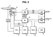
- Fig. 5 is a schematic diagram illustrating an optical disk apparatus having an LD drive for recording data on an optical disk in accordance with a preferred embodiment of the present invention.
- the optical disk apparatus can include an optical pick-up unit 20 for recording data on an optical disk 10 such as a CD-R disk, and detecting a recording signal from a recording surface of the optical disk 10.
- a digital recording signal processor 30a is preferably for adding an Error Correction Code (ECC) to received digital data, converting the received digital data into a recording format, reconverting the recording-formatted data into a bit stream, and generating a main pulse on the basis of the bit stream simultaneously with generating a sub-pulse having a prescribed pulse width at a prescribed time prior to generating the main pulse.
- ECC Error Correction Code
- a Radio Frequency (RF) unit 40 is preferably for generating driving voltages of VDRC, VWDC1 and VWDC2, filtering a signal detected by the optical pick-up unit 20, and generating the filtered signal as
- the optical disk apparatus can further include an LD drive 50, a drive unit 70, a servo unit 60, a digital playback signal processor 30b, a Read Only Memory (ROM) 81 and a microcomputer (MICOM) 80.
- the LD drive 50 is for receiving driving pulses and driving voltages from the digital recording signal processor 30a and the RF unit 40, respectively, and generating an LD driving signal on the basis of the driving pulses and voltages to control an optical power level of the optical pick-up unit 20.
- the drive unit 70 is for rotating a spindle motor M and sliding the optical pick-up unit 20 back and forth.
- the servo unit 60 is for controlling an operation of the drive unit 70 on the basis of servo error signals F.E and T.E and a rpm signal of the optical disk 10 and the digital playback signal processor 30b is preferably for restoring the binary signal to original data by means of its own clock signal being phase-locked with the binary signal.
- the ROM 81 is for storing variables for applying desired or optimal Write Strategies to individual recording pits 3T ⁇ 11T for every disk manufacturer (e.g., every disk code) and the microcomputer (MICOM) 80 is for executing a recording operation on the basis of the variables stored in the ROM 81.
- the optical pick-up unit 20 can have an LD driven by an LD driving signal (e.g., preferably indicative of a current value) of the LD drive 50.
- the LD drive 50 outputs the LD driving signal to the LD upon receiving driving voltages of VRDC, VWDC1 and VWDC2 and driving pulses PWO, PEO and LDH. The function of providing the LD driving signal by the LD drive 50 will be described below.
- VRDC is preferably a driving voltage required for reading data
- VWDC1 is preferably a main driving voltage required for recording data
- VWDC2 is preferably a sub driving voltage corresponding to additional overpower required for correctly or more accurately and stably forming initial recording pits during a data recording time using the main driving voltage VWDC1.
- PWO can be a driving pulse for the voltage VRDC.
- PEO can be a driving pulse for the main driving voltage VWDC1, and is preferably adapted as a main pulse.
- LDH can be a driving pulse for the sub driving voltage VWDC2, and is adapted as a sub pulse.
- the sub pulse LDH preferably has a signal level identical with that of the main pulse PEO.
- the present invention is not intended to be so limited.
- the driving voltages of VRDC, VWDC1 and VWDC2 are preferably transmitted from the RF unit 40 to the LD drive 50, and may also be transmitted from the digital recording signal processor 30a to the LD drive 50.
- the driving pulses PWO, PEO and LDH are preferably transmitted from the digital recording signal processor 30a to the LD drive 50.
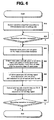
- Fig. 6 is a flow chart illustrating a preferred embodiment of the present invention an LD driving method for recording data on an optical disk in accordance with the present invention.
- the LD driving method shown in Fig. 6 can be applied to the apparatus of Fig. 5 and will be described referencing the same.
- the variety of variables for recording methods including a variable VRDC, time variables Td and Tf for generating a main pulse PEO, other time variables Ta and Tb for generating a sub pulse LDH, and other variables VWDC1 and VWDC2.
- the time variables Td and Tf can designate an ON timing and an OFF timing of the main pulse PEO, respectively.
- the other time variables Ta and Tb can designate an ON timing and an OFF timing of the sub pulse LDH, respectively.
- variable VWDC2 is identical with the variable VWDC2 in preferred embodiments according to the present invention, such that a variety of variables VWDC1 can be detected while being classified according to individual disk manufacturers and individual recording pits, and are then stored in the ROM 81 or the like.
- a variety of time variables Td and Tf can be detected while being classified according to individual disk manufacturers and individual recording pits, and are then stored in the ROM 81.
- Recording pits 3T ⁇ 11T of all the disk manufacturers preferably have the same values of Ta and Tb, such that they are detected while being classified according to individual disk manufacturers, and are then stored in the ROM 81.
- variable Ta designates a duty ratio of 50% that is preferably experimentally detected
- variable Tb designates a pulse width, for example of T/32, also experimentally detected where T preferably corresponds to a drive period of a LD for a smallest recording pit.
- the variables Ta and Tb may be different for every disk manufacturer.
- the microcomputer 80 determines a manufacturer name of the CD-R disk 10. For example, the microcomputer 80 can detect a start time of a lead-out area from Table Of Contents (TOC) information recorded on a lead-in area of the CD-R disk 10, and determine a manufacturer of the CD-R disk 10 on the basis of the detected start time of such lead-out area.
- TOC Table Of Contents
- the lead-out area designates an area of a signal indicative of a program termination, but individual disk manufacturers can have different start times in their lead-out areas, such that the microcomputer 80 can discriminate a correct manufacturer of the CD-R disk 10 among many manufacturers.
- the microcomputer 80 preferably can detect variables, which have been stored in the ROM 81 while having been classified according to individual manufacturers and individual recording pits, from the ROM 81 at step S10.
- the detected variables may be adjusted to desired or optimal values in response to characteristics of the CD-R disk 10 through the use of an Operation Planning Control (OPC) operation of the microcomputer 80.
- OPC Operation Planning Control
- the microcomputer 80 selects three variables VRDC, VWDC1 and VWDC2 (e.g., VWDC1) from among many variables detected while being classified according to individual pits to be recorded, and preferably applies the selected three variables VRDC, VWDC1 and VWDC2 to the RF unit 40 and the digital recording signal processor 30a, respectively.
- the variable Ta is a duty ratio of 50%
- the other variable Tb is preferably a pulse width of T/32 where T is a pulse width of a minimum pulse.
- the digital recording signal processor 30a can generate a main pulse PEO serving as a driving pulse of the variable VWDC1 on the basis of two variables Td and Tf, generate a sub pulse LDH serving as a driving pulse of the variable VWDC2 on the basis of two variables Ta and Tb, and generate a driving pulse PWO of the variable VRDC at step S21.
- the digital recording signal processor 30a transmits the pulses PEO, LDH and PWO to the LD drive 50.
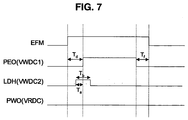
- the digital recording signal processor 30a can preferably first generate the sub pulse LDH at a prescribed time prior to generating the main pulse PEO on the basis of the variable Ta received from the microcomputer 80 at step S22.
- the variable Ta is set to a prescribed duty ratio (e.g., 50%)
- the digital recording signal processor 30a preferably generates a pulse signal of about 50% of the pulse width T/32 prior to generating the main pulse.
- a signal level of the main pulse PEO can be identical with that of the sub pulse LDH.
- Such examples of PEO, LDH and PWO are shown in Fig. 7.
- the RF unit 40 preferably outputs the driving voltages of VRDC, VWDC1 and VWDC2 to the LD drive 50.
- driving voltages are exemplarily shown in Fig. 8.
- the LD drive 50 can receive driving voltages of VRDC, VWDC1 and VWDC2 from the RF unit 40, and can generate them by the use of a switching operation of the driving pulses PEO, LDH and PWO preferably received from the digital recording signal processor 30a.
- the LD drive 50 preferably outputs an LD driving signal shown in Fig. 9 to an LD contained in the optical pick-up unit 20 at step S23. Therefore, the optical pick-up unit 20 records data on the CD-R disk 10 at an optical power level being adjusted by the LD driving signal at step S24. Then, it is determined at step S30 whether such a recording operation is terminated. If it is determined at step S30 that the recording operation is terminated, a process is also terminated. Otherwise, if it is determined at step S30 that the recording operation is not terminated, control can return to step S21.
- Fig. 9 is a diagram illustrating an LD driving signal and a signal waveform being recorded on the CD-R disk 10 using the LD driving signal.
- the LD driving signal can overlap with a rising edge of the main pulse PEO and a rising edge of the sub pulse LDH.
- a rising edge of the LD driving signal is variably depending on the waveform of the sub pulse LDH, such that the rising time of the LD driving signal can be reduced.
- Fig. 10 is a diagram illustrating a comparative result among the conventional Mode 1 (i.e., Orange 1), the conventional Mode 2 (i.e., Orange 2), and a preferred embodiment of a recording mode according to the present invention.
- a recording mode according to a preferred embodiment of the present invention can form recording pits being more accurately reproducible than the conventional Mode 2, however the conventional Mode 1 has the most stable recording waveform.
- preferred embodiments of an apparatus and method for driving a LD according to the present invention have various advantages.
- Preferred embodiments of the present invention need not set up the sub driving voltage VWDC2, and since the same values of Ta and Tb can be applied to individual recording pits, less system resources (e.g., less work and less time to detect and store variable values) are use relative to the conventional Mode 1.
- a recording quality of a data recording operation is similar to that of the conventional Mode 1, and forms a recording pit more correctly and stably than the conventional Mode 2.
- Preferred embodiment of the present invention can provide an apparatus and method for driving an LD for recording data on an optical disk such as a CD-R disk, which performs a data recording operation using an LD driving signal having no overpower as in the conventional Mode 2 (i.e. Orange 2), and takes less work and less time to detect and store variable values for optimal recording methods. Also, the apparatus correctly and stably forms recording pits each having a desired size at a desired time for a recording period of time as in the conventional Mode 1, resulting in improvement of the recording quality.
- the conventional Mode 2 i.e. Orange 2
Landscapes
- Physics & Mathematics (AREA)
- Optics & Photonics (AREA)
- Optical Recording Or Reproduction (AREA)
- Optical Head (AREA)
Applications Claiming Priority (2)
| Application Number | Priority Date | Filing Date | Title |
|---|---|---|---|
| KR10-2002-0084374A KR100521909B1 (ko) | 2002-12-26 | 2002-12-26 | 광디스크의 데이터 기록을 위한 레이저 다이오드 구동장치및 방법 |
| KR2002084374 | 2002-12-26 |
Publications (2)
| Publication Number | Publication Date |
|---|---|
| EP1434204A2 true EP1434204A2 (de) | 2004-06-30 |
| EP1434204A3 EP1434204A3 (de) | 2007-03-28 |
Family
ID=32464617
Family Applications (1)
| Application Number | Title | Priority Date | Filing Date |
|---|---|---|---|
| EP03029704A Withdrawn EP1434204A3 (de) | 2002-12-26 | 2003-12-23 | Vorrichtung und Verfahren zur Steuerung einer für Aufzeichnung von Daten auf einer optischen Platte verwendeten Laserdiode |
Country Status (5)
| Country | Link |
|---|---|
| US (1) | US7417932B2 (de) |
| EP (1) | EP1434204A3 (de) |
| JP (1) | JP4123438B2 (de) |
| KR (1) | KR100521909B1 (de) |
| CN (1) | CN1282961C (de) |
Families Citing this family (6)
| Publication number | Priority date | Publication date | Assignee | Title |
|---|---|---|---|---|
| US20050254367A1 (en) * | 2004-05-13 | 2005-11-17 | Volk Steven B | Microminiature optical disc drive with wireless capability |
| US7275252B2 (en) * | 2003-04-25 | 2007-09-25 | Vmedia Research, Inc. | Cell phone or other portable handset containing microminiature optical disc drive |
| US7983139B2 (en) * | 2007-11-30 | 2011-07-19 | Vmedia Research, Inc. | Small form factor optical data storage disc and cartridge |
| US8315144B2 (en) * | 2004-05-13 | 2012-11-20 | VMO Systems Inc. | Small form factor optical disc drive for use in mobile electronic device |
| KR20100101096A (ko) * | 2008-01-14 | 2010-09-16 | 엘지전자 주식회사 | 광디스크의 데이터 영구 삭제 장치 및 방법 |
| TWI440027B (zh) * | 2009-01-22 | 2014-06-01 | Sunplus Technology Co Ltd | 光學儲存裝置及其寫入功率暫態的消除方法 |
Citations (1)
| Publication number | Priority date | Publication date | Assignee | Title |
|---|---|---|---|---|
| JP2001067669A (ja) | 1999-08-31 | 2001-03-16 | Sony Corp | 記録装置、記録方法 |
Family Cites Families (5)
| Publication number | Priority date | Publication date | Assignee | Title |
|---|---|---|---|---|
| US5732062A (en) * | 1995-10-16 | 1998-03-24 | Ricoh Company, Ltd. | Information recording apparatus, method and computer program product |
| KR100297789B1 (ko) | 1999-06-03 | 2001-10-29 | 윤종용 | 다양한 형태의 광기록 매체에 적합한 기록 펄스 발생 방법 및이에 적합한 기록장치 |
| JP2001344752A (ja) | 2000-05-29 | 2001-12-14 | Sony Corp | 記録再生装置 |
| JP4419285B2 (ja) * | 2000-06-19 | 2010-02-24 | ソニー株式会社 | 光ディスク記録装置及び光ディスク記録方法 |
| JP3830755B2 (ja) * | 2000-11-30 | 2006-10-11 | 株式会社リコー | 光量制御装置と情報記録装置 |
-
2002
- 2002-12-26 KR KR10-2002-0084374A patent/KR100521909B1/ko not_active Expired - Fee Related
-
2003
- 2003-12-23 EP EP03029704A patent/EP1434204A3/de not_active Withdrawn
- 2003-12-23 CN CNB2003101222985A patent/CN1282961C/zh not_active Expired - Fee Related
- 2003-12-23 US US10/743,303 patent/US7417932B2/en not_active Expired - Fee Related
- 2003-12-26 JP JP2003433976A patent/JP4123438B2/ja not_active Expired - Fee Related
Patent Citations (1)
| Publication number | Priority date | Publication date | Assignee | Title |
|---|---|---|---|---|
| JP2001067669A (ja) | 1999-08-31 | 2001-03-16 | Sony Corp | 記録装置、記録方法 |
Also Published As
| Publication number | Publication date |
|---|---|
| US7417932B2 (en) | 2008-08-26 |
| KR20040057608A (ko) | 2004-07-02 |
| KR100521909B1 (ko) | 2005-10-13 |
| US20040136299A1 (en) | 2004-07-15 |
| CN1523588A (zh) | 2004-08-25 |
| JP4123438B2 (ja) | 2008-07-23 |
| JP2004213877A (ja) | 2004-07-29 |
| EP1434204A3 (de) | 2007-03-28 |
| CN1282961C (zh) | 2006-11-01 |
Similar Documents
| Publication | Publication Date | Title |
|---|---|---|
| US5502702A (en) | Optical disc recording device using basic recording information and projection time control | |
| US6975572B2 (en) | Optical disc apparatus with regulation of recording velocity and laser power | |
| EP1385157B1 (de) | Gerät zur Aufzeichnung einer optischen Platte, gesteuert mit Hilfe tabellierter Multi-Pulse | |
| JP2001067672A (ja) | 光ディスクの適正記録速度判定方法および記録速度設定方法ならびに記録方法 | |
| US20020015368A1 (en) | Information recording/reproducing apparatus and method and information recording medium | |
| US20080112289A1 (en) | Optical Disk Recording Apparatus and Optical Disk Recording Method | |
| JP2003296940A (ja) | 光ディスク装置 | |
| US7417932B2 (en) | Apparatus and method for driving laser diode for recording data on optical disk | |
| US7133340B2 (en) | Optical disc apparatus | |
| US6545956B2 (en) | Disc player and focus search control method | |
| US7596068B2 (en) | Apparatus and method for determining type of optical disk | |
| KR100613913B1 (ko) | 광기록재생기의 데이터 기록 방법 | |
| EP1875467A2 (de) | Aufzeichnungssystem zur einrichtung von schreibstrategien | |
| US7426159B2 (en) | Method of reproducing optical disk and optical disk reproducing apparatus | |
| US20020064109A1 (en) | Information record apparatus, information record method, and information record medium | |
| JP4329731B2 (ja) | 光ディスク装置 | |
| JP2003331427A (ja) | 光情報記録再生装置 | |
| KR100418480B1 (ko) | 광디스크의 데이터 기록방법 | |
| EP1615206B1 (de) | Aufzeichnungs-/Wiedergabegerät für optische Platten und Verfahren zur Bestimmung der optimalen Aufzeichnungsgeschwindigkeit dafür | |
| JP4479583B2 (ja) | 光ディスク装置 | |
| US7701828B2 (en) | Optical recording system and method | |
| KR100979937B1 (ko) | 광디스크장치의 오피씨 수행방법 | |
| EP1657714A2 (de) | Verfahren zur Durchführung einer Nachlaufregelung von Rohlingen | |
| US8233363B2 (en) | Method of controlling recording operation and optical disc drive employing the method | |
| JP2002319130A (ja) | 光記録再生装置 |
Legal Events
| Date | Code | Title | Description |
|---|---|---|---|
| PUAI | Public reference made under article 153(3) epc to a published international application that has entered the european phase |
Free format text: ORIGINAL CODE: 0009012 |
|
| AK | Designated contracting states |
Kind code of ref document: A2 Designated state(s): AT BE BG CH CY CZ DE DK EE ES FI FR GB GR HU IE IT LI LU MC NL PT RO SE SI SK TR |
|
| AX | Request for extension of the european patent |
Extension state: AL LT LV MK |
|
| PUAL | Search report despatched |
Free format text: ORIGINAL CODE: 0009013 |
|
| AK | Designated contracting states |
Kind code of ref document: A3 Designated state(s): AT BE BG CH CY CZ DE DK EE ES FI FR GB GR HU IE IT LI LU MC NL PT RO SE SI SK TR |
|
| AX | Request for extension of the european patent |
Extension state: AL LT LV MK |
|
| 17P | Request for examination filed |
Effective date: 20070620 |
|
| 17Q | First examination report despatched |
Effective date: 20070828 |
|
| AKX | Designation fees paid |
Designated state(s): DE FR GB NL |
|
| GRAP | Despatch of communication of intention to grant a patent |
Free format text: ORIGINAL CODE: EPIDOSNIGR1 |
|
| STAA | Information on the status of an ep patent application or granted ep patent |
Free format text: STATUS: THE APPLICATION IS DEEMED TO BE WITHDRAWN |
|
| 18D | Application deemed to be withdrawn |
Effective date: 20111230 |