EP1434401A1 - Egalisation temporelle utilisant des opérations dans le domaine fréquentiel - Google Patents
Egalisation temporelle utilisant des opérations dans le domaine fréquentiel Download PDFInfo
- Publication number
- EP1434401A1 EP1434401A1 EP02447271A EP02447271A EP1434401A1 EP 1434401 A1 EP1434401 A1 EP 1434401A1 EP 02447271 A EP02447271 A EP 02447271A EP 02447271 A EP02447271 A EP 02447271A EP 1434401 A1 EP1434401 A1 EP 1434401A1
- Authority
- EP
- European Patent Office
- Prior art keywords
- frequency domain
- equalizer
- signal
- dispersion
- samples
- Prior art date
- Legal status (The legal status is an assumption and is not a legal conclusion. Google has not performed a legal analysis and makes no representation as to the accuracy of the status listed.)
- Withdrawn
Links
- 239000011159 matrix material Substances 0.000 claims abstract description 35
- 239000006185 dispersion Substances 0.000 claims abstract description 34
- 230000005540 biological transmission Effects 0.000 claims abstract description 26
- 238000012545 processing Methods 0.000 claims abstract description 18
- 239000013598 vector Substances 0.000 claims abstract description 16
- 239000000969 carrier Substances 0.000 claims abstract description 9
- 238000000034 method Methods 0.000 claims description 25
- 230000001629 suppression Effects 0.000 claims description 20
- 230000004044 response Effects 0.000 claims description 10
- 230000003044 adaptive effect Effects 0.000 claims description 9
- 230000009467 reduction Effects 0.000 claims description 7
- 230000006978 adaptation Effects 0.000 claims description 5
- 230000008878 coupling Effects 0.000 claims description 2
- 238000010168 coupling process Methods 0.000 claims description 2
- 238000005859 coupling reaction Methods 0.000 claims description 2
- 238000000354 decomposition reaction Methods 0.000 abstract description 5
- 238000011156 evaluation Methods 0.000 abstract description 3
- 125000004122 cyclic group Chemical group 0.000 description 11
- 238000004891 communication Methods 0.000 description 9
- 238000004422 calculation algorithm Methods 0.000 description 8
- 230000006870 function Effects 0.000 description 8
- 238000012549 training Methods 0.000 description 7
- 230000008901 benefit Effects 0.000 description 5
- 230000001934 delay Effects 0.000 description 4
- 230000003190 augmentative effect Effects 0.000 description 2
- 238000004364 calculation method Methods 0.000 description 2
- 238000009795 derivation Methods 0.000 description 2
- 235000019800 disodium phosphate Nutrition 0.000 description 2
- 230000000694 effects Effects 0.000 description 2
- MYEJFUXQJGHEQK-ALRJYLEOSA-N Proscillaridin Chemical compound O[C@@H]1[C@H](O)[C@@H](O)[C@H](C)O[C@H]1O[C@@H]1C=C2CC[C@H]3[C@@]4(O)CC[C@H](C5=COC(=O)C=C5)[C@@]4(C)CC[C@@H]3[C@@]2(C)CC1 MYEJFUXQJGHEQK-ALRJYLEOSA-N 0.000 description 1
- XUIMIQQOPSSXEZ-UHFFFAOYSA-N Silicon Chemical compound [Si] XUIMIQQOPSSXEZ-UHFFFAOYSA-N 0.000 description 1
- 238000013459 approach Methods 0.000 description 1
- 230000000295 complement effect Effects 0.000 description 1
- 238000007796 conventional method Methods 0.000 description 1
- 230000007423 decrease Effects 0.000 description 1
- 238000010586 diagram Methods 0.000 description 1
- 230000006872 improvement Effects 0.000 description 1
- 238000005259 measurement Methods 0.000 description 1
- 230000003287 optical effect Effects 0.000 description 1
- 239000013307 optical fiber Substances 0.000 description 1
- 238000011084 recovery Methods 0.000 description 1
- 238000005070 sampling Methods 0.000 description 1
- 238000004904 shortening Methods 0.000 description 1
- 230000008054 signal transmission Effects 0.000 description 1
- 238000004088 simulation Methods 0.000 description 1
- 230000003595 spectral effect Effects 0.000 description 1
- 238000012546 transfer Methods 0.000 description 1
Images


Classifications
-
- H—ELECTRICITY
- H04—ELECTRIC COMMUNICATION TECHNIQUE
- H04L—TRANSMISSION OF DIGITAL INFORMATION, e.g. TELEGRAPHIC COMMUNICATION
- H04L25/00—Baseband systems
- H04L25/02—Details ; arrangements for supplying electrical power along data transmission lines
- H04L25/03—Shaping networks in transmitter or receiver, e.g. adaptive shaping networks
- H04L25/03006—Arrangements for removing intersymbol interference
- H04L25/03159—Arrangements for removing intersymbol interference operating in the frequency domain
-
- H—ELECTRICITY
- H04—ELECTRIC COMMUNICATION TECHNIQUE
- H04L—TRANSMISSION OF DIGITAL INFORMATION, e.g. TELEGRAPHIC COMMUNICATION
- H04L25/00—Baseband systems
- H04L25/02—Details ; arrangements for supplying electrical power along data transmission lines
- H04L25/03—Shaping networks in transmitter or receiver, e.g. adaptive shaping networks
- H04L25/03006—Arrangements for removing intersymbol interference
- H04L25/03012—Arrangements for removing intersymbol interference operating in the time domain
-
- H—ELECTRICITY
- H04—ELECTRIC COMMUNICATION TECHNIQUE
- H04L—TRANSMISSION OF DIGITAL INFORMATION, e.g. TELEGRAPHIC COMMUNICATION
- H04L27/00—Modulated-carrier systems
- H04L27/26—Systems using multi-frequency codes
- H04L27/2601—Multicarrier modulation systems
- H04L27/2647—Arrangements specific to the receiver only
Definitions
- This invention relates to circuits and methods for modeling a dispersive channel in a telecommunications system as well as to equalizers, to receivers and transmitters having such equalizers, to modems having such receivers and/or transmitters, to central office equipment having such modems, to signal processors, to corresponding software and methods, and to methods of offering a communication service over networks having such receivers and/or transmitters, especially for multi-carrier telecommunications systems in which a signal is transmitted and received over a dispersive channel.
- Asymmetric high speed Digital Subscriber Line (ADSL) and Very high speed Digital Subscriber Line (VDSL) are examples of modem communication systems which permit transmission of data over band-limited communication lines at very high rates, e.g., up to 52 Mbits/s. They are examples of multi-carrier systems. Reference is made to "ADSL, VDSL and Multicarrier Modulation", J. A. C. Bingham, Wiley, 2000. Multi-carrier modulation is a well known means of transmitting digital data by splitting that data into fixed-length data "blocks" or “symbols" each having the same number of sub-blocks or bits. Analogue transmission of these blocks is carried out using a set of carrier signals. There is a carrier for each of the sub-blocks in one block.
- the carriers have frequencies which are equally spaced across the transmission band of the transceiver.
- DMT Discrete multi-tone
- DMT modems transmit data by dividing it into several interleaved bit streams, and using these bit streams to modulate several carriers.
- OFDM Orthogonal Frequency Division Multiple Access
- R. van Nee and R. Prasad Orthogonal Component Interconnect
- Artech House 2000.
- Applications are for example, wireless LAN' s.
- This modulation technique also finds application in Satellite communications, see for example, “Satellite Communications Systems", G. Maral, M. Bousquet, Wiley, 1998.
- a DMT receiver following TEQ, the CP is removed, followed by a Fast Fourier Transform (FFT), complementary to the IFFT of the transmitter.
- FFT Fast Fourier Transform
- the signal can be then passed to a frequency domain equalizer (FDEQ), to recover the transmitted symbols, e.g. QAM symbols from which the bit streams are recovered.
- FDEQ frequency domain equalizer
- a transversal filter is a common choice for a linear equalizer.
- the tap coefficients correspond to the channel parameters and represent a "model" of the dispersive nature of the channel. If the coefficients are properly selected, the equalizer can attenuate ISI significantly.
- Equalization can involve a training sequence that is compared at the receiver with a locally-generated or otherwise known training sequence (cross-correlation).
- Adaptive equalization involves adapting the coefficients continually and automatically directly from the received data.
- a drawback of adaptive equalization is the computational "cost" involved in continually updating the filter coefficients so that the channel model is adapted to the current conditions of the channel.
- US patent 6,404,806 shows an example of an ADSL system having a TDEQ including an estimation of, and compensation for, echo on the line and the ingress of out of band noise, particularly RFI, into the in band channels.
- a method for training the TDEQ is used, which includes computing a Toeplitz autocorrelation matrix.
- US patent 6,353,629 shows time domain equalization techniques referred to as poly-path time domain equalization techniques; improved training methods for training transmitters and/or receivers of a data transmission system; and techniques for providing time domain equalization to a transmitter side of a data transmission system.
- the training methods involve Toeplitz matrices.
- United States Patent Application 20020106035 A1 shows a spectrally constrained impulse shortening filter for time domain equalisation in a DMT receiver.
- a target spectral response is calculated and the impulse response of the channel shortened so that a significant part of an energy of the impulse response is confined to a region that is shorter than a target length.
- an equalizer for a multi carrier transmission system for at least reducing delay dispersion in a signal
- the equalizer having a convertor arranged to convert a multi carrier signal into sampled frequency domain signals, and a suppressor for suppressing time domain delay dispersion, on the sampled frequency domain signals, the convertor being arranged to use a sequence of consecutive samples of the multicarrier signal, the sequence having a length of at least two symbols, to derive oversampled frequency domain signals for reduction of dispersion of one symbol.
- the suppressor may be adaptive according to feedback from a suppressed dispersion output signal at a receiving side.
- the suppressor may have a parameter generator arranged to use the feedback to generate adaptively a set of frequency domain dispersion parameters to suppress the dispersion from one symbol.
- the parameters may be configurable to adjust the suppression per carrier.
- the parameters may comprise a vector having a value for each of the carriers.
- the parameter generator may be arranged to derive the parameters using an impulse response of the transmission path.
- the equalizer may be arranged to separate odd and even samples of the oversampled frequency domain signal, for separate processing.
- the suppressor may be arranged to carry out Fourier transform based operations separately on the odd and even frequency domain samples.
- the Fourier transform based operations may be equivalent to a time domain equalization.
- the transform based operations can be derived from circulant decomposition of a Toeplitz matrix into a sum of a circulant and a skew circulant component of the matrix. This can reduce the computational overhead by replacing a matrix-vector multiplication by as few as four Fourier transforms.
- the transform operations may be arranged to implement the equation: where Y is the processed output, W are frequency domain signal processing parameters which can be used for adaptation, i.e. of the frequency-domain representation of the TEQ.
- F is the Fourier transform operator
- P is the constant diagonal operator diag ( ⁇ even ) are even ones of frequency domain samples
- diag ( ⁇ odd ) are odd ones of frequency domain samples.
- Another aspect provides a corresponding method of equalizing for multi carrier transmissions, for at least reducing delay dispersion in a signal, comprising converting a multi carrier signal into sampled frequency domain signals, and suppressing time domain delay dispersion, on the sampled frequency domain signals, the converting being arranged to use a sequence of consecutive samples of the multicarrier signal, the sequence having a length of at least two symbols, to derive oversampled frequency domain signals for reduction of dispersion of one symbol.
- the present invention provides a receiver having a demodulator for recovering data from a multicarrier input signal, and the equalizer of any preceding claim for equalizing the input signal.
- Another aspect of the present invention is a modem having a receiver as described above and a transmitter.
- the modems may be included in central office or customer premises' equipment each modem being for coupling a subscriber line to a telecommunications network.
- Another aspect of the present invention provides a signal processor for carrying out a time domain matrix type operation on an input signal, and having a convertor arranged to convert the input signal into oversampled frequency domain samples, and a processor arranged to carry out frequency domain transform operations on the frequency domain samples, the convertor being arranged to use a sequence of consecutive samples of the multicarrier signal, the sequence having a length of at least two symbols for reduction of dispersion of one symbol.
- the transform operations can be derived by circulant decomposition of the matrix into a circulant and a skew circulant component of the matrix.
- the signal processor may be adapted to carry out the transform operations-based on the equation: where Y is the processed output, W are frequency domain signal processing parameters which can be used for adaptation, i.e. of the frequency-domain representation of the TEQ.
- F is the Fourier transform operator
- P is the constant diagonal operator diag ( ⁇ even ) are even ones of frequency domain samples
- diag ( ⁇ old ) are odd ones of frequency domain samples.
- the signal processing parameters may comprise adaptively derived characteristics of a signal transmission path.
- the matrix type operation may be a compensation for distortion introduced by the transmission path. This can encompass equalization, echo cancellation such as is shown in the above referenced EP application, or any distortion which can be represented or approximated by a matrix which can be decomposed.
- the present invention also comprises a dispersive channel modelling device for modeling a dispersive path in a multicarrier telecommunications system.
- the device may have the signal processor described above.
- An equalizer in the form of software is intended to encompass software which runs on or controls "dumb” or standard hardware, to carry out the desired functions, (and therefore the software essentially defines the functions of the equalizer, and can therefore be termed an equalizer, even before it is combined with its standard hardware).
- software which "describes" or defines the configuration of hardware such as HDL (hardware description language) software, as is used for designing silicon chips, or for configuring universal programmable chips, to carry out desired functions.
- Another aspect provides a method of offering a communication service over a network using the receiver described above.
- the present invention will be described with reference to certain drawings and embodiments but these are provided by way of example only.
- the present invention may find wider application than these example, e.g. as indicated in the attached claims.
- the present invention may find application wherever a dispersive channel has to be modeled, e.g. in satellite, ADSL, VDSL, xDSL, wireless LAN applications.
- the physical nature of the channel is considered not limiting, e.g. air interface, cable, optical fibre, twisted pair, coax cable.
- Fourier transforms other transforms may be used.
- discrete wavelet transforms and inverse transforms may be used as explained in the book by J. A. C. Bingham mentioned above. The relationship between Fourier, wavelet and other transforms is explained in the book "Wavelets and Subbands", A. Abbate et al., Birkhäuser, 2002.
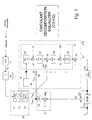
- a modem 225 having a discrete multi-tone (DMT) transceiver which includes a receiver 235 employing an equalizer 260 according to respective embodiments of the present invention.
- the modem is coupled to a subscriber line for transmitting or receiving to or from consumer premises equipment CPE 200.
- CPE 200 consumer premises equipment
- the embodiments are equally applicable at the CPE or in other types of multicarrier communications links such as cable connections, wireless links and so on.
- the modem is shown incorporated in central office equipment having other functions 240 such as mux or demux or switching, to couple many subscriber lines via modems to the rest of the PSTN or other networks 400.
- the transceiver includes a transmitter portion having a mapper for receiving data to be modulated and transmitted, and a signal output for outputting transmit signals to a digital-to-analog converter (DAC) 5 for subsequent transmission.
- the transceiver also includes a receiver portion having a receive signal input for receiving signals transmitted from remote transceivers via an analog-to-digital converter (ADC) 6, and a receive data output for outputting dispersion suppressed received data to a demapper 240.
- a transmission path exists from the transmitter portion output to the CPE, and another exists in the reverse direction to the receiver portion input along the subscriber line.
- the path includes at least a hybrid transformer (not shown) of the transceiver and may include other elements of the transceiver located outside the transmitter portion and the receiver portion of the transceiver.
- an inverse fast Fourier transform unit (IFFT) 2 receives input data in the form of frequency-domain DMT data blocks comprised of N complex-valued data elements.
- the IFFT unit 2 modulates each of the N data elements with N carrier signals at evenly spaced frequency intervals thereby converting the N frequency-domain data elements into a block (or "symbol") of N real-valued time-domain samples.
- a cyclic prefix block (CPB) 3 may be provided.
- the cyclic prefix block 3 may copy the last L samples of the N time-domain sample block to form a cyclic prefix therewith, and prepends the cyclic prefix to the beginning of the block.
- the cyclic prefix may also be placed at other positions in the data stream. This is done in order to reduce inter-block interference at the remote transceiver to which the block of (N+L) samples is subsequently transmitted.
- the output of the cyclic prefix block 3 is DMT transmit signals comprising a plurality of time-domain multi-carrier transmit blocks/symbols.
- the DMT transmit signals are subsequently passed through a transmitter low-pass filter unit 4 and thence through a digital-to-analogue converter 5 prior to duplex transmission to a remote transceiver.
- the receiver portion input is coupled to an analogue-to-digital converter (ADC) 6 arranged to digitise received DMT time-domain signals received from a remote transceiver, and to pass those signals, so digitised, through a receiver filter 7.
- ADC analogue-to-digital converter
- a frequency-domain processing, equivalent to time domain equalization' is subsequently applied by TEQ 260 to the signals output of the receive filter 7 to produce DMT time-domain dispersion suppressed received signals.
- the TEQ involves frequency domain operations.
- An FFT convertor 30 generates frequency domain samples using a block of 2N or more input samples to create an oversampled set of frequency samples. These are used by the frequency domain delay dispersion suppressor 270.
- the suppression is adaptive using coefficients generated by an adaptation algorithm 265. This can be based on feedback from dispersion suppressed outputs taken from a point downstream in the processing chain.
- the coefficients can be frequency domain coefficients.
- the output of the TEQ is fed to a conventional frequency domain equalizer 250 which can serve to resize and rotate the ISI/ICI-free carriers, so that they can fit into the constellation grid of the demapper 240 to produce de-modulated data samples following conventional principles.
- the output of the receiver side of the modem is passed on to other parts of the central office equipment for onward routing and transmission. Other parts of the modem such as echo cancellation, clock offset processing and so on are not shown for the sake of clarity. Echo cancellation can be achieved using the techniques shown in the above referenced European patent application.
- Figure 2 shows an embodiment of an equalizer either for use in the modem of figure 1 or in other applications. It shows the convertor taking in time domain samples of the multicarrier transmitted signal, and producing frequency domain samples. These are effectively oversampled by carrying out the Fourier transform over a block at least 2N in length where N is the number of carriers.
- the convertor has two separate outputs representing odd frequency domain samples and even frequency domain samples respectively.
- Fourier transform type operations are carried out on these outputs, by parts 284 and 286 respectively.
- the operations also use frequency domain coefficients adapted by algorithm 265 to provide feedback.
- the delay dispersion suppressor 270 incorporates the transform operations and generates a combined output which is effectively a frequency-domain equalized output.
- one aspect of the present invention is implementation or emulation of a TEQ in the 'oversampled' frequency-domain.
- T i,i-1 is the state vector of the received signal, represented as an NxN Toeplitz matrix with symbol length N (i.e.
- the embodiment illustrated in more detail in Figure 3 is one way of implementing the following basic mathematical derivations: - the Toeplitz matrix T in equation (1) will first be augmented to form a (2Nx2N) circulant matrix C where: and, where S is derived from the elements of T.
- the matrix C is thereby circulant such that where in accordance with common general knowledge of matrix algebra whereby a circulant matrix can always be written as a product of its Fourier transform F 2N with a diagonal matrix and with its inverse Fourier transform.
- the vector C 1 is the first column of matrix C.
- Y i is generated directly in the frequency-domain as follows: where the W i are frequency-domain equalization parameters, which may be updated according to the adaptive update formula; where E i is the dispersion suppressed frequency-domain receive block.
- the updated equalization parameters W i+1 may be calculated adaptively using known adaptive update algorithms to estimate the value of the scalar weighting term ⁇ , such as the Least Mean Square (LMS) or MMSE (Minimum Mean Square Error) adaptive update algorithms for example, as is well known in the art.
- LMS Least Mean Square
- MMSE Minimum Mean Square Error
- an equalizer comprising a convertor 30 connected to the output of the receive filter.
- the convertor comprises a 2xDMT sampler unit 31 for sampling pairs of consecutive DMT transmit blocks/symbols "u i-1 " and "u i " and generating the 2Nx1 vector [T 1 ;S 1 ] therefrom for input to a fast Fourier transform (FFT) unit 32.
- the FFT unit 32 generates a frequency domain block ⁇ comprising 2N or more frequency-domain data samples, and passes the block into an "even/odd splitter" signal divider unit 35.
- the signal divider unit 35 is arranged to generate a first sub-block diag( ⁇ even ) and a second sub-block diag ( ⁇ odd ) which are each derived from the frequency domain block vector ⁇ derived from the input received from the 2xDMT unit 31.
- the first sub-block comprises the even-numbered (i.e. 2 nd , 4 th , 6 tn , ...) data elements of the frequency domain block ⁇ while the second sub-block comprises the remaining odd-numbered elements thereof.
- the signal divider unit 35 outputs each of the first and second sub-blocks on separate output ports.
- the convertor 30 is arranged to input only the first sub-block diag ( ⁇ even ) to a conjugator unit 34 of an equalization parameter updating unit 33.
- the conjugator unit 34 is arranged to form the complex conjugate of data input thereto and to output the result to multiplier unit 34b.
- the convertor is arranged to output both the first sub-block and the second sub-block diag ( ⁇ odd ) to separate multiplier units 38 and 43 respectively for subsequent use as will be explained below.
- the multiplier unit 34b of the equalizer is arranged to receive as input the complex conjugate of the first sub-block diag ( ⁇ even ) from the conjugator unit 34, a scalar weighting term ⁇ calculated according to an LMS or MMSE algorithm (not shown) such as is well known in the art and a frequency-domain block E i output by the subtractor 252 described below.
- the multiplier unit 34b is operable to generate frequency domain equalization update parameters by multiplying together the inputs received thereby to form the quantity;
- the suppression parameter generator 36 and the convertor 30 respectively provide suppression parameters (when updated or otherwise) and frequency domain blocks as an input to a suppressor 100.
- the suppressor is arranged to receive first and second frequency domain sub-blocks from the signal divider unit 35.
- the suppressor comprises a first multiplier unit 38, a transformer unit 37 and an adder unit 39.
- the signal divider unit 35 is arranged to generate an even sub-block diag ( ⁇ even ) and an odd sub-block diag ( ⁇ odd ) and to direct the even sub-block to an input of the first multiplier unit 38. Simultaneously the odd sub-block is directed to an input of the transformer unit 37 so as to be transformed thereby according to a first predetermined transform operation.
- the suppression parameter generator 36 is arranged to simultaneously input suppression parameters to the first multiplier unit 38 and the transformer unit 37 for pre-multiplication by the even sub-block and the odd sub-block (transformed according to the first transform operation) respectively thereby to produce a first and a second suppression sub-component.
- the outputs of the first multiplier unit 38 and the transformer means 37 are directed to inputs of the adder unit 39 which adds those inputs together to provide as output a frequency-domain suppression component Y ⁇ , as defined in the second term of eq.(14), namely:
- the transformer unit 37 comprises the following components connected in sequence: a first N-point inverse fast Fourier transform (IFFT) unit 40, a first operator multiplier unit 41, a first N-point fast Fourier transform unit (FFT) 42, a second multiplier unit 43, a second N-point inverse fast Fourier transform (IFFT) unit 44, a second operator multiplier unit 45, and a second N-point fast Fourier transform unit (FFT) 46.
- IFFT inverse fast Fourier transform
- FFT N-point fast Fourier transform
- FFT N-point fast Fourier transform unit
- the first N-point inverse fast Fourier transform (IFFT) unit 40 is arranged to receive suppression parameters input from the suppression parameter generator 36, to transform those parameters accordingly and to output the result as a first input of the first operator multiplier unit 41.
- the first operator unit is also arranged to receive as a second input a parameter block representing the diagonal operator P, to pre-multiply its first input with the parameter block of its second input and to output the result to an input of the first N-point fast Fourier transform unit 42.
- the first N-point fast Fourier transform (FFT) unit 42 is arranged to transform its input accordingly and to output the result as a first input of the second multiplier unit 43.
- the second multiplier unit is also arranged to receive as a second input the odd sub-block from the convertor, to pre-multiply its first input with its second input and to output the result to the input of the second N-point inverse fast Fourier transform (IFFT) unit 44.
- IFFT inverse fast Fourier transform
- the second N-point inverse fast Fourier transform (IFFT) unit 44 is arranged to transform its input accordingly and to output the result as a first input of the second operator multiplier unit 45.
- the second operator unit is also arranged to receive as a second input a parameter block representing the inverse of diagonal operator P, to pre-multiply its first input with the parameter block of its second input and to output the result to an input of the first fast Fourier transform unit 46.
- the second N-point fast Fourier transform (FFT) unit 46 is arranged to transform its input accordingly and to output the result as the second suppression sub-component and the output of the transformer unit 37.
- the slicer 254 in ADSL/DMT can also be implemented as a demapper. However, merely for use with the equalizer, recovery of the full bit-stream is not necessary but only the per-tone error Ei is required i.e. the difference between the received (equalized) constellation point and the ⁇ decided' point which corresponds to the sent constellation in case of no transmission-errors. Hence, a full demapper is not required.
- An error signal Ei is generated by subtractor 252 to give an indication of a level of ISI/ICI remaining.
- Ei contains only the residual ISI/ICI in the frequency-domain for each tone (i.e. subcarrier of the multi-carrier modulation), this is the error which drives the update as the aim of the equalizer is to put this error to zero.
- Ei is fed back to the updater unit 33 as described above for use in frequency-domain update parameter generation for updating the parameter generator 36 to construct the quantity arising in eq.(16), namely:
- TEQ/FEQ coefficients can be directly used with the CD-EQ receiver (the V vector is just the FFT over N points of the TEQ taps). So, existing equalizers can be replaced by those of the embodiments described, by additionally converting the TEQ coefficients from the time domain to the frequency domain.
- TEQ can be updated using normal MMSE algorithms for example directly in the frequency domain.
- Overall complexity can be comparable with traditional TEQ/FEQ receivers (the structure can be efficiently implemented with DSP cores).
- Any of the functions shown can be implemented using standard software languages or procedures, for execution on standard hardware such as general purpose microprocessors, DSPs, or application specific integrated circuits, for example.
- the software contains code which may execute on any suitable computing device or processing engine having memory such as a microprocessor, e.g. Pentium IV supplied by Intel Corp. USA or similar, or a programmable gate array such as a Field Programmable Gate Array, Programmable Array Logic, Programmable Logic Array or similar.
- the software may also be stored on a suitable data carrier, e.g. an optical disk such as a CD-ROM, a DVD-ROM; magnetic tape; a hard disk; a memory of a network element in a telecommunications network or in a personal computer or a work station such as a UNIX workstation
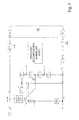
- FIG. 4 shows how corresponding techniques can be used for other signal processing applications, including modeling transmission path characteristics for example.
- a signal processor 292 includes a convertor 30 for outputting frequency domain samples to an element 380 for carrying out frequency domain operations. These are transform operations arranged to achieve an equivalent operation on a Toeplitz matrix by vector multiplication on the original time domain signal.
- the transforms are derived from circulant decomposition of the original Toeplitz matrix into a sum of a circulant and skew circulant matrix components. This can be implemented using the transformer 37 of figure 3.
- Adaptation using feedback in the form of an error signal is enabled in the form of vector values which are converted to frequency domain parameters.
- the error Ei is namely an N-length complex vector which carries the residual ISI/ICI error for each tone.
- Fig. 5 is a block diagram of an echo canceller disclosed in European patent application EP 02291217.
- the common features between this echo canceller and an equaliser of this invention is a dispersive channel modeling device which is arranged to use a sequence of consecutive samples of a multicarrier signal, the sequence having a length of at least two symbols, to derive oversampled frequency domain signals for simulation of dispersion caused by the channel.
- the subtraction point in the canceller is replaced by the "slicer" in the equalizer.
- the training signal is the transmitted signal in the canceller and the received signal in the equalizer.
- the P and P * vectors are exchanged order compared to the description above, however this makes no substantial difference. From a mathematical point of view the two versions give the same output.
- a dispersive channel modeling device e.g. in an equalizer for a multi carrier transmission system that converts a transmitted multi carrier signal into sampled frequency domain signals, and suppresses time domain delay dispersion, on the sampled frequency domain signals. It exploits circulant decomposition of a Toeplitz matrix to enable the computationally heavy evaluation of a matrix multiplied by a vector, to be avoided. Increased precision arises from the frequency domain processing being equivalent to a longer time domain FIR filter than is normally practical. The amount of compensation for different carriers can be adjusted, which can lead to increased precision.
Landscapes
- Engineering & Computer Science (AREA)
- Computer Networks & Wireless Communication (AREA)
- Signal Processing (AREA)
- Power Engineering (AREA)
- Cable Transmission Systems, Equalization Of Radio And Reduction Of Echo (AREA)
Priority Applications (6)
| Application Number | Priority Date | Filing Date | Title |
|---|---|---|---|
| EP02447271A EP1434401A1 (fr) | 2002-12-24 | 2002-12-24 | Egalisation temporelle utilisant des opérations dans le domaine fréquentiel |
| DE60313158T DE60313158D1 (de) | 2002-05-17 | 2003-05-19 | Zeitbereichsentzerrung unter verwendung von frequenzbereichsoperationen |
| AU2003229148A AU2003229148A1 (en) | 2002-05-17 | 2003-05-19 | Time domain equalization using frequency domain operations |
| EP03724678A EP1506653B1 (fr) | 2002-05-17 | 2003-05-19 | Egalisation dans le domaine temporel au moyen d'operations dans le domaine frequentiel |
| US10/514,690 US7623578B2 (en) | 2002-05-17 | 2003-05-19 | Time domain equalization using frequency domain operations |
| PCT/BE2003/000087 WO2003098832A2 (fr) | 2002-05-17 | 2003-05-19 | Egalisation dans le domaine temporel au moyen d'operations dans le domaine frequentiel |
Applications Claiming Priority (1)
| Application Number | Priority Date | Filing Date | Title |
|---|---|---|---|
| EP02447271A EP1434401A1 (fr) | 2002-12-24 | 2002-12-24 | Egalisation temporelle utilisant des opérations dans le domaine fréquentiel |
Publications (1)
| Publication Number | Publication Date |
|---|---|
| EP1434401A1 true EP1434401A1 (fr) | 2004-06-30 |
Family
ID=32405847
Family Applications (1)
| Application Number | Title | Priority Date | Filing Date |
|---|---|---|---|
| EP02447271A Withdrawn EP1434401A1 (fr) | 2002-05-17 | 2002-12-24 | Egalisation temporelle utilisant des opérations dans le domaine fréquentiel |
Country Status (1)
| Country | Link |
|---|---|
| EP (1) | EP1434401A1 (fr) |
Cited By (2)
| Publication number | Priority date | Publication date | Assignee | Title |
|---|---|---|---|---|
| WO2013184927A1 (fr) * | 2012-06-08 | 2013-12-12 | Deere & Company | Récepteur de signal à compensation de temps de propagation de groupe |
| US8837654B2 (en) | 2012-06-08 | 2014-09-16 | Deere & Company | Signal receiver with group delay and amplitude distortion compensation |
Citations (2)
| Publication number | Priority date | Publication date | Assignee | Title |
|---|---|---|---|---|
| DE4233222A1 (de) * | 1992-10-02 | 1994-04-07 | Siemens Ag | Meßsystem (Channel Sounder) zur Untersuchung von Mobilfunkkanälen |
| US20020146078A1 (en) * | 2001-02-22 | 2002-10-10 | Alexei Gorokhov | Multicarrier transmission system with reduced complexity channel response estimation |
-
2002
- 2002-12-24 EP EP02447271A patent/EP1434401A1/fr not_active Withdrawn
Patent Citations (2)
| Publication number | Priority date | Publication date | Assignee | Title |
|---|---|---|---|---|
| DE4233222A1 (de) * | 1992-10-02 | 1994-04-07 | Siemens Ag | Meßsystem (Channel Sounder) zur Untersuchung von Mobilfunkkanälen |
| US20020146078A1 (en) * | 2001-02-22 | 2002-10-10 | Alexei Gorokhov | Multicarrier transmission system with reduced complexity channel response estimation |
Non-Patent Citations (2)
| Title |
|---|
| ACKER VAN K ET AL: "PER TONE EQUALIZATION FOR DMT-BASED SYSTEMS", IEEE TRANSACTIONS ON COMMUNICATIONS, IEEE INC. NEW YORK, US, vol. 49, no. 1, 1 January 2001 (2001-01-01), pages 109 - 119, XP001038829, ISSN: 0090-6778 * |
| VAN ACKER K ET AL: "Frequency domain equalization with tone grouping in DMT/ADSL-receivers", SIGNALS, SYSTEMS, AND COMPUTERS, 1999. CONFERENCE RECORD OF THE THIRTY-THIRD ASILOMAR CONFERENCE ON OCT. 24-27, 1999, PISCATAWAY, NJ, USA,IEEE, US, 24 October 1999 (1999-10-24), pages 1067 - 1070, XP010373800, ISBN: 0-7803-5700-0 * |
Cited By (3)
| Publication number | Priority date | Publication date | Assignee | Title |
|---|---|---|---|---|
| WO2013184927A1 (fr) * | 2012-06-08 | 2013-12-12 | Deere & Company | Récepteur de signal à compensation de temps de propagation de groupe |
| US8837653B2 (en) | 2012-06-08 | 2014-09-16 | Deere & Company | High frequency signal receiver with self-calibrated group delay compensation |
| US8837654B2 (en) | 2012-06-08 | 2014-09-16 | Deere & Company | Signal receiver with group delay and amplitude distortion compensation |
Similar Documents
| Publication | Publication Date | Title |
|---|---|---|
| EP1506653B1 (fr) | Egalisation dans le domaine temporel au moyen d'operations dans le domaine frequentiel | |
| US7519132B2 (en) | Reduced complexity multicarrier precoder | |
| US6185251B1 (en) | Equalizer for use in multi-carrier modulation systems | |
| AU750466B2 (en) | A multicarrier receiver | |
| US7697615B2 (en) | Subdimensional single-carrier modulation | |
| WO2003012990A1 (fr) | Systemes et procedes concus pour une modulation a porteuses multiples au moyen d'un egaliseur a prises multiples dans le domaine frequence et d'une decision retroactive | |
| WO1999052250A1 (fr) | Filtre servant a raccourcir une reponse impulsionnelle et possedant des contraintes spectrales supplementaires afin d'emettre sur des porteuses multiples | |
| US7224725B2 (en) | Method for determining coefficients of an equalizer and apparatus for determining the same | |
| US6233276B1 (en) | XDSL modem having time domain filter for ISI mitigation | |
| CN100459448C (zh) | 频域回波消除器 | |
| US6563841B1 (en) | Per-bin adaptive equalization in windowed DMT-type modem receiver | |
| EP1420557B1 (fr) | Égalisation combinée pour un récepteur de type DMT | |
| EP1434402B1 (fr) | Interpolateur fractionnel de domaine temporel | |
| US6687288B1 (en) | NEXT cancellation for modem pools | |
| KR100348903B1 (ko) | 초고속 디지털 가입자망의 등화 시스템 및 그 방법 | |
| EP1434401A1 (fr) | Egalisation temporelle utilisant des opérations dans le domaine fréquentiel | |
| JP2002208909A (ja) | 通信システム雑音妨害を除去する方法および装置 | |
| EP1545083A1 (fr) | Appareil et procédé de complexité reduite pour égalisation de chaque porteuse dans un système multiporteuse | |
| KR100440833B1 (ko) | 이산 멀티톤 변조를 이용하여 발생시킨 신호를 위한디지탈 수신기 | |
| EP1556963A1 (fr) | Annuleur d'echo non lineaire multietage pour systemes de communication numerique avec ou sans duplexage par repartition en frequence | |
| US6647076B1 (en) | Method of compensating for interference in a signal generated by discrete multitone modulation, and circuit configuration for carrying out the method. | |
| EP1296492B1 (fr) | Récepteur multiporteuse avec une transformation de Fourier a fenêtre glissante et transformation de Fourier | |
| EP1303093B1 (fr) | Raccourciment de la réponse impulsionelle dans des modems de type DMT | |
| US7342975B2 (en) | Circuit arrangement and method for compensating for disturbances in a signal generated by means of discrete multitone modulation | |
| US7260144B2 (en) | Architecture for per tone equalizer with reduced complexity for DMT-based xDSL modems |
Legal Events
| Date | Code | Title | Description |
|---|---|---|---|
| PUAI | Public reference made under article 153(3) epc to a published international application that has entered the european phase |
Free format text: ORIGINAL CODE: 0009012 |
|
| AK | Designated contracting states |
Kind code of ref document: A1 Designated state(s): AT BE BG CH CY CZ DE DK EE ES FI FR GB GR IE IT LI LU MC NL PT SE SI SK TR |
|
| AX | Request for extension of the european patent |
Extension state: AL LT LV MK RO |
|
| AKX | Designation fees paid | ||
| REG | Reference to a national code |
Ref country code: DE Ref legal event code: 8566 |
|
| STAA | Information on the status of an ep patent application or granted ep patent |
Free format text: STATUS: THE APPLICATION IS DEEMED TO BE WITHDRAWN |
|
| 18D | Application deemed to be withdrawn |
Effective date: 20041231 |