EP1434433A2 - Système de projection de plusieurs signaux à résolution complète et procédé de projection de deux images voisines à résolution complète - Google Patents
Système de projection de plusieurs signaux à résolution complète et procédé de projection de deux images voisines à résolution complète Download PDFInfo
- Publication number
- EP1434433A2 EP1434433A2 EP03024176A EP03024176A EP1434433A2 EP 1434433 A2 EP1434433 A2 EP 1434433A2 EP 03024176 A EP03024176 A EP 03024176A EP 03024176 A EP03024176 A EP 03024176A EP 1434433 A2 EP1434433 A2 EP 1434433A2
- Authority
- EP
- European Patent Office
- Prior art keywords
- image
- high resolution
- display
- format
- projection
- Prior art date
- Legal status (The legal status is an assumption and is not a legal conclusion. Google has not performed a legal analysis and makes no representation as to the accuracy of the status listed.)
- Withdrawn
Links
Images
Classifications
-
- G—PHYSICS
- G06—COMPUTING OR CALCULATING; COUNTING
- G06F—ELECTRIC DIGITAL DATA PROCESSING
- G06F3/00—Input arrangements for transferring data to be processed into a form capable of being handled by the computer; Output arrangements for transferring data from processing unit to output unit, e.g. interface arrangements
- G06F3/14—Digital output to display device ; Cooperation and interconnection of the display device with other functional units
- G06F3/1423—Digital output to display device ; Cooperation and interconnection of the display device with other functional units controlling a plurality of local displays, e.g. CRT and flat panel display
- G06F3/1446—Digital output to display device ; Cooperation and interconnection of the display device with other functional units controlling a plurality of local displays, e.g. CRT and flat panel display display composed of modules, e.g. video walls
-
- G—PHYSICS
- G09—EDUCATION; CRYPTOGRAPHY; DISPLAY; ADVERTISING; SEALS
- G09G—ARRANGEMENTS OR CIRCUITS FOR CONTROL OF INDICATING DEVICES USING STATIC MEANS TO PRESENT VARIABLE INFORMATION
- G09G3/00—Control arrangements or circuits, of interest only in connection with visual indicators other than cathode-ray tubes
- G09G3/001—Control arrangements or circuits, of interest only in connection with visual indicators other than cathode-ray tubes using specific devices not provided for in groups G09G3/02 - G09G3/36, e.g. using an intermediate record carrier such as a film slide; Projection systems; Display of non-alphanumerical information, solely or in combination with alphanumerical information, e.g. digital display on projected diapositive as background
- G09G3/002—Control arrangements or circuits, of interest only in connection with visual indicators other than cathode-ray tubes using specific devices not provided for in groups G09G3/02 - G09G3/36, e.g. using an intermediate record carrier such as a film slide; Projection systems; Display of non-alphanumerical information, solely or in combination with alphanumerical information, e.g. digital display on projected diapositive as background to project the image of a two-dimensional display, such as an array of light emitting or modulating elements or a CRT
-
- H—ELECTRICITY
- H04—ELECTRIC COMMUNICATION TECHNIQUE
- H04N—PICTORIAL COMMUNICATION, e.g. TELEVISION
- H04N21/00—Selective content distribution, e.g. interactive television or video on demand [VOD]
- H04N21/40—Client devices specifically adapted for the reception of or interaction with content, e.g. set-top-box [STB]; Operations thereof
- H04N21/43—Processing of content or additional data, e.g. demultiplexing additional data from a digital video stream; Elementary client operations, e.g. monitoring of home network or synchronising decoder's clock; Client middleware
- H04N21/431—Generation of visual interfaces for content selection or interaction; Content or additional data rendering
- H04N21/4312—Generation of visual interfaces for content selection or interaction; Content or additional data rendering involving specific graphical features, e.g. screen layout, special fonts or colors, blinking icons, highlights or animations
- H04N21/4316—Generation of visual interfaces for content selection or interaction; Content or additional data rendering involving specific graphical features, e.g. screen layout, special fonts or colors, blinking icons, highlights or animations for displaying supplemental content in a region of the screen, e.g. an advertisement in a separate window
-
- H—ELECTRICITY
- H04—ELECTRIC COMMUNICATION TECHNIQUE
- H04N—PICTORIAL COMMUNICATION, e.g. TELEVISION
- H04N21/00—Selective content distribution, e.g. interactive television or video on demand [VOD]
- H04N21/40—Client devices specifically adapted for the reception of or interaction with content, e.g. set-top-box [STB]; Operations thereof
- H04N21/47—End-user applications
-
- H—ELECTRICITY
- H04—ELECTRIC COMMUNICATION TECHNIQUE
- H04N—PICTORIAL COMMUNICATION, e.g. TELEVISION
- H04N5/00—Details of television systems
- H04N5/74—Projection arrangements for image reproduction, e.g. using eidophor
-
- H—ELECTRICITY
- H04—ELECTRIC COMMUNICATION TECHNIQUE
- H04N—PICTORIAL COMMUNICATION, e.g. TELEVISION
- H04N9/00—Details of colour television systems
- H04N9/12—Picture reproducers
- H04N9/31—Projection devices for colour picture display, e.g. using electronic spatial light modulators [ESLM]
- H04N9/3141—Constructional details thereof
- H04N9/3147—Multi-projection systems
Definitions
- the present invention relates to a projection device and a method for projection of a plurality of images adjacent each other onto a visualisation surface such as a screen. More particularly it relates to a projection device and method for projection of a plurality of images at full resolution, especially using fixed format display devices.
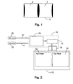
- each projector has its own projection lens with its own geometrical aberrations or distortions. Projecting a plurality of such distorted images adjacent each other always involves some bad alignment, as represented for example in Fig. 1, which shows two images 2, 4 projected adjacent each other onto a projection surface 6 by two different projectors. Each of the images 2, 4 is distorted.
- a device With this device, a pair of discrete images are disposed in adjoining relation on a view screen to form a single image thereon with minimal or no illuminance discontinuity at their juncture.
- a light source a condensing lens, a mirror system, a pair of discrete image displays, and a projection lens.
- the lens and mirror system project light rays from the source along discrete optical paths for passage separately through each image display.
- a single projection lens defining an optical axis is provided for projecting the images in adjoining relation on a view screen.
- an optical system including a lens and mirror for combining the light rays passing through the image displays along discrete optical paths for passage through the projection lens such that a single image combining the images from the discrete image displays in substantially seamless adjoining relation is formed on the view screen.
- the above device has the disadvantage that the two image displays need to be aligned very accurately. It is known that such mechanical adjustments of two image displays, LCD panels for example, diverge under temperature cycling circumstances. Furthermore, if the characteristics of the image displays for forming the adjacent projected images are different, then a join seam becomes visible on the screen. This join seam is caused by a difference between the characteristics of the image displays, and accordingly the quality of the projected image deteriorates. Making two exactly identical image displays is difficult (in reality impossible) due to process differences. This is especially true for grey levels on the image displays, such as LCD's for example. Furthermore, the seam is also visible because the light beam is split into two parts, one for each panel, resulting in illuminance and colour non uniformity.
- the present invention provides a projection device.
- Such projection device comprises:
- the first and second image formats may be the same and the first and second display formats may be the same.
- the image forming display device may comprise a number of monochromatic image forming display devices which in combination form a projected coloured image.
- the image forming display may be made up of one or more fixed format devices. Due to the use of one large image forming display for displaying the two images, the problem of geometrical alignment, which existed in the prior art solutions, is solved. The reason for this is that as the two images are combined together to form a single array, the dividing line between the two images is selectable on a pixel-by-pixel basis. Once the dividing line is determined the image will project in the same way at all times as the dividing line is set into the fixed format of the display device. Also the colour non-uniformity problem is solved, because one single light beam is used for the two images.
- the first and second display formats may be the same, or they may be different. They may have the same or a different frame rate.
- the frame rate of the third display format may be the same as that of either of the first of second display formats, or it may be different from both.
- the third frame rate is preferably a single frame rate for the complete image thus avoiding the necessity for conditional updating.
- the image forming display device may be a wide aspect ratio panel, e.g. a flat panel display. It may be a transmissive display such as e.g. an LCD panel, or a reflective display such as e.g. a DMD or an LCOS, or a transreflective display.
- a transmissive display such as e.g. an LCD panel
- a reflective display such as e.g. a DMD or an LCOS, or a transreflective display.
- the image recombination system may comprise a Field Programmable Gate Array or other similar computing device.
- the input signals may be high resolution input signals, e.g. they may have a resolution SVGA or higher.
- the present invention also provides a projection system with a projection device and a visualisation surface.
- the projection device of such projection system comprises:
- the first and second image formats may be the same and the first and second display formats may be the same.
- the present invention furthermore provides a method for projecting two high resolution images adjacent each other.
- the method comprises:
- the first and second image formats and the first and second display formats may be the same.
- the present invention provides a single projection system that may comprise one or more projection devices and that has at least two input channels 12, 14, preferably high resolution input channels.
- the projection device is able to capture high resolution input signals relating to two full resolution data or computer images.
- resolution in the context of display interfaces is often used to refer to the "image format” or “adressibility”, i.e. the horizontal and vertical pixel count in a fixed format device.
- image format refers what is called “resolution” in the art, i.e. the number of pixels in the vertical and horizontal direction.
- display format includes not only the image format but also other information required to display the image, e.g. the frame rate, the blanking periods.
- Each image signal has information relating to the length of the lines of the image as well as information from which it can be decided which parts of the image signals are image pixels to be displayed.
- This type of information is contained in the image signals received on the first and second channels and can be, for example, blanking periods for a first and second display format, respectively.
- the first and second display format may be the same.
- a complete video signal, whether analog or digital, includes information corresponding to the image itself, but also generally has additional "overhead” requirements. In the situation of an analog video signal, the "overhead" is in the blanking period, i.e. that portion of the signal that is intentionally left free of active content, or of information corresponding to a part of the image itself.
- the requirement for such periods is imposed by the needs of the various imaging and display hardware technologies, which must have some idle time between each scanned line and frame or field in order to reset and prepare for the next.
- the blanking period almost always contains the signals which provide synchronisation information to the display - those pulses or signals which identify the start of a new line, field or frame. It is common, then, to divide the overall blanking period into three sections. The period prior to the synchronisation pulse is the "front porch". The remainder of the blanking period is then divided into the sync pulse itself and the "back porch" (which is any remaining blanking time following the end of the sync pulse).
- the "overhead" will be in an information data part of the image signal, which for example defines the number of pixels per line for the image, and/or the frame rate, i.e. the number of images that are displayed per second.
- This information data then refers to the image format.
- the term "information data” is used both for analog and digital image signals, and thus includes either blanking periods or other information data relating to the way the image format is to be displayed on a particular device. This is to be distinguished from "image data" that contains the information with respect to each image pixel to be displayed.
- a projection device 10 is able to display these data or computer images in native resolution or otherwise next to or adjacent each other, as shown in Fig. 2, and therefore has an image recombination system 24 for combining the high resolution input signals 20, 22 into one high resolution imaging signal having data information, e.g. blanking periods, for a third display format larger than either of the first or second display formats, and a high resolution image forming display device 18 for displaying an image corresponding to the high resolution imaging signal.
- “high resolution” is meant having four hundred thousand pixels or more, preferably one million pixels or more, more preferred two million pixels or more.
- the projection device 10 may comprise more than one monochromatic projection devices, e.g. three such devices for projection three primary colour images.
- the combination of the two input images is displayed from each monochromatic projection device.
- the three images are superimposed on a display screen to form a single full-colour image which comprises the two input images in the same resolution.
- the display devices may be fixed format display devices, e.g. flat panel devices and may include tiled displays.
- the present invention also provides a projection system, comprising a projection device 10 and a visualisation screen 16.
- a projection system may comprise a fixed format projector, e.g. a flat panel projector such as an LCD projector as a projection device 10.
- a flat panel projector such as an LCD projector as a projection device 10.
- Such an LCD projector may have three image forming display devices 18, e.g. the LCD projector may be a three-panel (one panel for each colour) LCD projector, wherein each panel has a "resolution" of e.g. 2050*1208 pixels. This corresponds to the resolution of two standard XGA panels next to each other.
- the aspect ratio of the image forming display devices 18, e.g. LCD panels may be larger than the aspect ratio of a normal image forming display device, e.g. LCD panel, for example the aspect ratio may be 16:9 or 16:10 instead of 4:3.
- the projection device may be, but does not need to be, a two-lamp projector, which fits better with the 16:9 or 16:10 aspect ratio of the image forming display devices 18. Thanks to the resolution of the image forming display panels 18, in the example given it is possible to display two native XGA-sources of each 1024*768 pixels next to each other simultaneously without the need for two projectors. In such a case the frame rate for the complete image is the same all over the image.
- the electronics inside the projection device 10 are capable of handling two or more separate data streams 20, 22 and of combining them in full resolution in an image recombination system 24 into one image format that is then sent to the image forming display device 18 inside the projection device 10, as shown on the example in Fig. 2.
- the data streams or input signals 20, 22 may for example be analog R, G, B, H, V signals or digital DVI-signals or equivalent with a resolution of VGA, SVGA, XGA or higher.
- the image recombination system 24 may function as follows: each image 20, 22 is presented to the image recombination system 24 as a datastream comprising consecutive lines of the images 20, 22.
- the recombined image comprises, for each n th line, data from the n th line of the first image 20 and data from the n th line of the second image 22.
- This combination of lines of data from the separate images 20, 22 into lines of data of the combined image is made inside the image recombination system 24.
- the two image formats are combined into 1 bigger image format, which is presented to the display.
- the whole screen is continuously and real time updated, so the update is not conditionally, i.e. the update is not for parts of the display only.
- the frame rate of the combined image that is fed to the display will usually be (but does not need to be) synchronous with the frame rate of 1 of the two inputted formats, for example with the frame rate of the first image format. If the second image format has a different frame rate, this second image format will be frame rate converted to match the frame rate of the first image format and of the combined image format that is combining both images for the display.
- one or each input channel of the projection device of the present invention may include a frame converter, e.g. in block 24. It is possible that the combined image format is running asynchronously from both inputted image formats, in which case both inputted formats are frame rate converted using a frame converter to match the frame rate of the combined image format that is fed to the display.
- both inputted image formats are frame rate matched to the combined image format that will be sent to the display
- combining the pixel data of both images into the combined image format creates the combined image data.
- the pixel data of each individual input image is mapped to the correct position in the combined image, thereby recalculating the correct pixel position for all pixels of the combined image.
- the combined image being synchronous or asynchronous with at least one of the images, both images are displayed at the same frame rate.
- the electronic image processing system comprises a dual data line for computer or data images with a 1:1 resolution preservation, i.e. no downscaling nor upscaling of the image resolutions.
- both images are shifted into one big data image by image recombination techniques applied to the image signals in an image recombination system 24.
- the recombination of these two data streams may be done in an image recombination system 24 such as e.g. an Integrated Circuit (IC), an Application Specific IC (ASIC), or a Field Programmable Gate Array (FPGA), which combines both images e.g. into a 2050*1208-image format.
- IC Integrated Circuit
- ASIC Application Specific IC
- FPGA Field Programmable Gate Array
- This 2050*1208-image format signal is then fed to the large image forming display device 18, e.g. LCD panel, and is projected onto the visualisation screen or projection screen 16 by means of a single projection lens 26. Because both images 28, 30 are projected by a single projection lens 26 in a single projection device 10, there is no risk of geometrical misalignment between the images 28, 30 because of geometrical distortion and neither for colour misalignment as is the case when one is using two separate projection systems next to each other as in the prior art.
- the two images can be visually placed on the visualisation screen 16 either next to each other, horizontally, vertically or obliquely, or partially on top of each other.
- the image processing electronics first measures characteristics of each of the inputted image signals 20, 22, such as for example resolution, blanking, total number of pixels, etc and then uses this data to accurately map the pixels of the inputted data files into the combined image format. If for example the first image comprises more lines than the second image, then blank lines (or black lines) may be added at the end of the second image when combining both images. Thus the image format of the final image may be greater than the sum of the image formats of the first and second images.
- the different images are displayed at the same frame rate in the final image.
- the projection device 10 can be a single lamp system or a multiple lamp system, and it can display video images as well as data images. Alternatively, the illumination can also happen with laser sources.
- the image forming display device 18 inside the projection device 10 can be of a transmissive or reflective type, such as for example a polysilicon LCD, a DLP-chip, a DMD display, an LCOS device, a grating light valve display or an OLED display, as long as the resolution is sufficient for the application.
- the projection device 10 can either be a single display projector, a 2-display projector or a 3-display projector. The embodiments above have been explained for the combination of two images, but more than two images may be combined as well.
Landscapes
- Engineering & Computer Science (AREA)
- Multimedia (AREA)
- Signal Processing (AREA)
- Theoretical Computer Science (AREA)
- Physics & Mathematics (AREA)
- General Physics & Mathematics (AREA)
- Human Computer Interaction (AREA)
- Marketing (AREA)
- General Engineering & Computer Science (AREA)
- Business, Economics & Management (AREA)
- Computer Hardware Design (AREA)
- Control Of Indicators Other Than Cathode Ray Tubes (AREA)
- Liquid Crystal Display Device Control (AREA)
- Transforming Electric Information Into Light Information (AREA)
- Projection Apparatus (AREA)
Applications Claiming Priority (2)
| Application Number | Priority Date | Filing Date | Title |
|---|---|---|---|
| US10/330,943 US6848792B1 (en) | 2002-12-27 | 2002-12-27 | Full resolution multiple image projection system and method for projecting two images in full resolution adjacent each other |
| US330943 | 2002-12-27 |
Publications (2)
| Publication Number | Publication Date |
|---|---|
| EP1434433A2 true EP1434433A2 (fr) | 2004-06-30 |
| EP1434433A3 EP1434433A3 (fr) | 2008-03-19 |
Family
ID=32469052
Family Applications (1)
| Application Number | Title | Priority Date | Filing Date |
|---|---|---|---|
| EP03024176A Withdrawn EP1434433A3 (fr) | 2002-12-27 | 2003-10-20 | Système de projection de plusieurs signaux à résolution complète et procédé de projection de deux images voisines à résolution complète |
Country Status (2)
| Country | Link |
|---|---|
| US (1) | US6848792B1 (fr) |
| EP (1) | EP1434433A3 (fr) |
Cited By (2)
| Publication number | Priority date | Publication date | Assignee | Title |
|---|---|---|---|---|
| US11029592B2 (en) | 2018-11-20 | 2021-06-08 | Flightsafety International Inc. | Rear projection simulator with freeform fold mirror |
| US11122243B2 (en) | 2018-11-19 | 2021-09-14 | Flightsafety International Inc. | Method and apparatus for remapping pixel locations |
Families Citing this family (14)
| Publication number | Priority date | Publication date | Assignee | Title |
|---|---|---|---|---|
| JP3729189B2 (ja) * | 2003-07-18 | 2005-12-21 | ソニー株式会社 | 撮像装置 |
| TWI307081B (en) * | 2005-03-24 | 2009-03-01 | Via Tech Inc | Multi-view video switch control method and system |
| TWI266530B (en) * | 2005-07-29 | 2006-11-11 | Coretronic Corp | Projector |
| US20070055941A1 (en) * | 2005-09-08 | 2007-03-08 | Bhakta Dharmesh N | Method and apparatus to selectively display portions of a shared desktop in a collaborative environment |
| US20070120763A1 (en) * | 2005-11-23 | 2007-05-31 | Lode De Paepe | Display system for viewing multiple video signals |
| US20070206120A1 (en) * | 2006-03-03 | 2007-09-06 | Nottage Maurice A | Double screen television |
| EP1876814A1 (fr) * | 2006-07-07 | 2008-01-09 | Barco NV | Non-linéair mappage d'image utilisant une pluralité de planes non-coplanar |
| US8164600B2 (en) * | 2007-12-06 | 2012-04-24 | Barco Nv | Method and system for combining images generated by separate sources |
| US9122444B2 (en) * | 2012-02-08 | 2015-09-01 | Ricoh Company, Ltd. | Network accessible projectors that display multiple client screens at once |
| US9291886B2 (en) | 2013-08-30 | 2016-03-22 | American Tack & Hardware Co., Inc. | Animated projection system |
| CN105793918B (zh) * | 2013-09-27 | 2019-01-22 | 皇家飞利浦有限公司 | 同时显示多个视频源的视频数据 |
| JP7081200B2 (ja) | 2018-02-22 | 2022-06-07 | セイコーエプソン株式会社 | 画像表示装置、及び画像表示装置の制御方法 |
| CN113556497A (zh) * | 2020-04-26 | 2021-10-26 | 北京君正集成电路股份有限公司 | 一种传输多摄像头数据的方法 |
| CN117079584A (zh) * | 2023-08-16 | 2023-11-17 | 南京芯视元电子有限公司 | 全彩发光二极管显示驱动及显示方法、驱动及显示装置 |
Family Cites Families (8)
| Publication number | Priority date | Publication date | Assignee | Title |
|---|---|---|---|---|
| JPH1023377A (ja) * | 1996-07-05 | 1998-01-23 | Toshiba Corp | テレビジョン受信機を利用したテキストデータ処理装置 |
| US5719667A (en) * | 1996-07-30 | 1998-02-17 | Bayer Corporation | Apparatus for filtering a laser beam in an analytical instrument |
| KR100270815B1 (ko) * | 1997-11-05 | 2000-11-01 | 윤종용 | 부화상 표시방법 및 장치 |
| US6538675B2 (en) * | 1998-04-17 | 2003-03-25 | Canon Kabushiki Kaisha | Display control apparatus and display control system for switching control of two position indication marks |
| JP4541476B2 (ja) * | 1999-02-19 | 2010-09-08 | キヤノン株式会社 | マルチ画像表示システムおよびマルチ画像表示方法 |
| JP2002010165A (ja) * | 2000-06-26 | 2002-01-11 | Sony Corp | 多画面表示装置および多画面表示方法 |
| KR100386579B1 (ko) * | 2000-07-18 | 2003-06-02 | 엘지전자 주식회사 | 멀티 소스용 포맷 변환 장치 |
| JP3797129B2 (ja) * | 2001-03-28 | 2006-07-12 | セイコーエプソン株式会社 | 光学部品の取付構造およびプロジェクタ |
-
2002
- 2002-12-27 US US10/330,943 patent/US6848792B1/en not_active Expired - Lifetime
-
2003
- 2003-10-20 EP EP03024176A patent/EP1434433A3/fr not_active Withdrawn
Cited By (6)
| Publication number | Priority date | Publication date | Assignee | Title |
|---|---|---|---|---|
| US11122243B2 (en) | 2018-11-19 | 2021-09-14 | Flightsafety International Inc. | Method and apparatus for remapping pixel locations |
| US11595626B2 (en) | 2018-11-19 | 2023-02-28 | Flightsafety International Inc. | Method and apparatus for remapping pixel locations |
| US11812202B2 (en) | 2018-11-19 | 2023-11-07 | Flightsafety International Inc. | Method and apparatus for remapping pixel locations |
| US12192686B2 (en) | 2018-11-19 | 2025-01-07 | Flightsafety International Inc. | Method and apparatus for remapping pixel locations |
| US11029592B2 (en) | 2018-11-20 | 2021-06-08 | Flightsafety International Inc. | Rear projection simulator with freeform fold mirror |
| US11709418B2 (en) | 2018-11-20 | 2023-07-25 | Flightsafety International Inc. | Rear projection simulator with freeform fold mirror |
Also Published As
| Publication number | Publication date |
|---|---|
| US6848792B1 (en) | 2005-02-01 |
| EP1434433A3 (fr) | 2008-03-19 |
Similar Documents
| Publication | Publication Date | Title |
|---|---|---|
| US6848792B1 (en) | Full resolution multiple image projection system and method for projecting two images in full resolution adjacent each other | |
| US7364313B2 (en) | Multiple image projection system and method for projecting multiple selected images adjacent each other | |
| US10244202B2 (en) | Image processing method, system for laser TV and the laser TV set thereof | |
| EP1115105B1 (fr) | Affichage par projection avec affichage OSD et compensation des distortions de l' image | |
| US20100117929A1 (en) | Multi-display system, information processor, and image data processing method in multi-display system | |
| US20100220247A1 (en) | Digital correction module for video projector | |
| Shimizu | 40.1: invited paper: scrolling color LCOS for HDTV rear projection | |
| US20090002297A1 (en) | Image display device | |
| US20090022411A1 (en) | Image display apparatus | |
| US7880713B2 (en) | Method of increasing efficiency of video display and related apparatus | |
| TW202019149A (zh) | 影像控制裝置以及使用該裝置之電視牆系統與輸出影像至電視牆的控制方法 | |
| JP2006078505A (ja) | 表示装置および方法 | |
| US11803347B2 (en) | Image display system and image display method | |
| US20090273540A1 (en) | System and Method for Providing Uniform Brightness in Seam Portions of Tiled Images | |
| JP2003322908A (ja) | 投射システム | |
| US20060119561A1 (en) | Image display apparatus, image signal converting device, image signal converting method, image signal converting program | |
| US7064795B2 (en) | Temporal dithering to increase dynamic range of images in sequentially illuminated displays | |
| EP0978819A1 (fr) | Appareil de visualisation d'images | |
| JPH08289237A (ja) | プロジエクタ装置 | |
| JP2010197449A (ja) | 画像投影システムと画像投影方法 | |
| JPH05134268A (ja) | 画像再生液晶デイスプレイ装置 | |
| JP3228767B2 (ja) | 液晶パネル及び液晶表示装置 | |
| US20020113891A1 (en) | Multi-frequency video encoder for high resolution support | |
| JP3269389B2 (ja) | 表示装置 | |
| JP3082202B2 (ja) | 液晶投射ディスプレイ |
Legal Events
| Date | Code | Title | Description |
|---|---|---|---|
| PUAI | Public reference made under article 153(3) epc to a published international application that has entered the european phase |
Free format text: ORIGINAL CODE: 0009012 |
|
| AK | Designated contracting states |
Kind code of ref document: A2 Designated state(s): AT BE BG CH CY CZ DE DK EE ES FI FR GB GR HU IE IT LI LU MC NL PT RO SE SI SK TR |
|
| AX | Request for extension of the european patent |
Extension state: AL LT LV MK |
|
| PUAL | Search report despatched |
Free format text: ORIGINAL CODE: 0009013 |
|
| AK | Designated contracting states |
Kind code of ref document: A3 Designated state(s): AT BE BG CH CY CZ DE DK EE ES FI FR GB GR HU IE IT LI LU MC NL PT RO SE SI SK TR |
|
| AX | Request for extension of the european patent |
Extension state: AL LT LV MK |
|
| RIC1 | Information provided on ipc code assigned before grant |
Ipc: H04N 5/445 20060101ALI20080212BHEP Ipc: H04N 5/74 20060101AFI20040407BHEP |
|
| 17P | Request for examination filed |
Effective date: 20080923 |
|
| AKX | Designation fees paid |
Designated state(s): AT BE BG CH CY CZ DE DK EE ES FI FR GB GR HU IE IT LI LU MC NL PT RO SE SI SK TR |
|
| R17P | Request for examination filed (corrected) |
Effective date: 20080919 |
|
| STAA | Information on the status of an ep patent application or granted ep patent |
Free format text: STATUS: THE APPLICATION IS DEEMED TO BE WITHDRAWN |
|
| 18D | Application deemed to be withdrawn |
Effective date: 20100504 |