EP1434935B1 - Procede et dispositif pour pulveriser des liquides au moyen d'ecoulements gazeux - Google Patents
Procede et dispositif pour pulveriser des liquides au moyen d'ecoulements gazeux Download PDFInfo
- Publication number
- EP1434935B1 EP1434935B1 EP02777303A EP02777303A EP1434935B1 EP 1434935 B1 EP1434935 B1 EP 1434935B1 EP 02777303 A EP02777303 A EP 02777303A EP 02777303 A EP02777303 A EP 02777303A EP 1434935 B1 EP1434935 B1 EP 1434935B1
- Authority
- EP
- European Patent Office
- Prior art keywords
- gas
- laval nozzle
- liquid
- fuel
- channel
- Prior art date
- Legal status (The legal status is an assumption and is not a legal conclusion. Google has not performed a legal analysis and makes no representation as to the accuracy of the status listed.)
- Expired - Lifetime
Links
Images


Classifications
-
- F—MECHANICAL ENGINEERING; LIGHTING; HEATING; WEAPONS; BLASTING
- F02—COMBUSTION ENGINES; HOT-GAS OR COMBUSTION-PRODUCT ENGINE PLANTS
- F02M—SUPPLYING COMBUSTION ENGINES IN GENERAL WITH COMBUSTIBLE MIXTURES OR CONSTITUENTS THEREOF
- F02M67/00—Apparatus in which fuel-injection is effected by means of high-pressure gas, the gas carrying the fuel into working cylinders of the engine, e.g. air-injection type
- F02M67/10—Injectors peculiar thereto, e.g. valve less type
Definitions
- the invention relates to a method and a device for atomising liquids with the help of of gas streams and the use of such Contraption.
- a uniform atomization is in addition to the internal combustion engines, like petrol engines in two-stroke or Four-stroke or diesel engines also for other internal combustion engines, like gas turbines and others Force from burns producing apparatus, such as Thrust engines with their combustion chambers and also for Boiler and the like desirable.
- the fuels are thereby liquid fuels and in the Gases for combustion are usually air, which they are referred to below, even if it is not just air, but also to aid their mixing with the combustion Gases acts.
- the invention is therefore based on the object Method and device for atomizing To create liquids by means of gas streams with which the liquid in as fine a droplet achieved in close and / or controlled distribution become.
- This particular, meanwhile also referred to as Nanoval method has principle in the atomization of molten metal as advantageous proved (DE 33 11 343), by fine particles arise in close distribution and become good spherical form as a powder.
- the inventive Atomization is from the mass flows of both media gas and liquid and the surface tension and viscosity of the liquid substantially certainly. These are gas flows in the range of the speed of sound up into the supersonic, ie in air currents and over 300 m / s.
- the gas flow around the liquid jet is laminar and is constantly accelerated. This is served by the injector, rather something below her arranged Lavaldüse of convergent divergent Cross-section.
- the Beam diameter increases in its interior the pressure against the external surface tension.
- the gas is accelerated, the pressure in it decreases and there is a bursting of the liquid jet, if the surface forces do not hit the beam can hold together more. This is done as a license plate of the process abruptly and approximately in the area the narrowest cross-section of the Laval nozzle or in Running direction afterwards.
- the liquid droplets spread to the side, because the sudden bursting superimposed as a result of the predominant internal pressure the forward momentum of the liquid jet.
- the mixture formation is improved in the atomization of fuel oils in burners increases the efficiency and reduces the harmfulness of the exhaust gases, in atomizing nozzles for colors, finishes, humidification - here by the laminar type of atomization low noise - And also the advantage of finer particles used in close distribution.
- the droplet size does not vary so much in particular, no too large droplets are generated, if not, as with diesel engines sometimes at different ranges when filling the Combustion chamber is desired, and the entire Combustion chamber is evenly filled by the mixture.
- the expansion of the from air and liquid formed by mixture Expansion at one corner the so-called Prandtl-Meyer-Strömung, be used after which a supersonic flow at one corner in the following Space is expanding, in strong widening until over 90 ° to the original flow direction. Prerequisite is a supersonic flow before and a further expansion opportunity by one after the corner following deeper pressure.
- the invention makes the possibility of sudden expansion use a supersonic jet. Due to the dilution and shockwaves can be the mixing of Liquid, e.g. Fuel and air are improved.
- Essential in the inventive method and the device, in particular for use in the Automotive sector, is the mixture production through an accompanying air flow, which is a part, but also represents the entire combustion air.
- a pure air flow into the cylinder be blown at the same time for flushing the combustion chamber is used, and the fuel jet then introduced into the existing airflow
- air and fuel can, too to stream at the same time.
- the parallel flow between Gas and liquid keeps the liquid jet up to the Aufplatztician together, and indeed longer than this happens in other sputtering processes.
- the pressure atomization is lower than in the prior art the pressure atomization.
- the apparatus and method of the invention are designed to burst into both Media, gas and liquid, laminar flow is present.
- This is basically the invention accelerated gas flow, while a delayed Flow as in injecting into still air one Subject to destabilization and fanned turbulence becomes.
- it comes only after the bursting in or after the passage of sound to shock waves and dilution waves and then also to turbulence. But since the droplets are already formed. Both, supersonic shock waves and turbulence, promotes the mixing of laminar Droplets with the air, in the case of internal combustion engines the fuel droplet with the Combustion air.
- the two-substance atomizing device according to the invention can also reduce exhaust gas pollutants, detached from the combustion process, then afterwards be used on it, as it is with partial load Exhaust gas recirculation or with separate treatment of the mixture, e.g. with urea, happens.
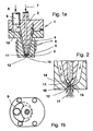
- a Device for atomizing according to the invention shown, in the present case, the device for use in the automotive sector as an injection device is described.
- the injection or Atomizing device has a housing 1, a first part 2 with a liquid or Fuel channel 4 forming through hole and an annulus 10 includes.
- the liquid or Fuel channel 4 is connected to a not shown Fluid or fuel supply connected, while a manifold connected to the annulus 10 9 to a gas or air source, not shown connected.
- a lower one Part 3 of the housing provided, in which to a Zerstäubungsraum open a Laval nozzle 5 is formed.
- the upper part 2 is inserted in the lower part and centered that between them an annular gap channel 6 is formed, which communicates with the annular space 10 in connection stands. Furthermore, the fuel channel 4 opens into a capillary 14, which in turn is in the area of closest cross-section 12 of the Laval nozzle 5 optionally also something below ends.
- the device according to Figures 1a and 1b is e.g. on a suction pipe of the engine or directly on the cylinder head or attached to the combustion chamber of a gas turbine.
- These are basically small Dimensions.
- the flow cross section of the liquid channel 4 in the upper part only in the millimeter range and the outlet 15 of the capillary 14, depending on the engine power or cylinder, for the mixture is prepared, in tenths of a millimeter range, and accordingly, the inner diameter for the annular gap channel 6, which is the lower Area 11 tapers, just a few millimeters.
- the liquid fuel is according to the arrow 7 introduced into the fluid channel 4, while the Air flows along the arrows 8 in the manifold 9 and from there distributed in the annulus 10 and flows into the annular gap channel 6.
- Im rejuvenating lower area 11 decreases the air speed steadily until they are in the narrowest 12 of the Laval nozzle 5 passes.
- Will the critical pressure ratio exceeded, so here is speed of sound, but never again.
- the described strong expansion on a corner can to an extension of the Laval nozzle 5 after the narrowest cross section, also by taking back the contour connect, leaving a corner or even a return is formed, which is a sudden spread of the liquid-gaseous medium allowed. requirement is a supersonic flow previously.
- On short ways can be characterized by a strong spread of the mixture, as generally desired.
- the distraction is stronger, the larger the Supersonic speed in the extended part of the Laval nozzle 5 is, i. the higher the Mach number that the Ratio of the velocity at the outlet of the Laval nozzle to the speed of sound in the narrowest cross-section represents the Laval nozzle.
- Atomizing air can be used, be it that it is is a continuous atomization of the fuel, as in gas turbines or intermittently, as in most cases with gasoline and diesel engines.
- Atomizing air can be used for mixture formation in one Cylinder the previously achieved higher pressures of another can be used and stored in storage tanks compressed air from cylinders over opening and closing valves are fed.
- Methods are known and used e.g. in the US 2 134 786 or DE 37 32 259.
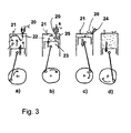
- Fig. 3 is another embodiment of Invention shown schematically, which is here is the working cycle of a two-stroke engine. This is a measure in which with the atomization by means of enveloping combustion air jets higher Speeds the engine power at given Effort can be increased.
- this embodiment becomes a clock-controlled injection nozzle 20 according to the device according to the invention used, which opens into a cylinder chamber 22. Of the Cylinder also has an exhaust valve 21 on.
- injection nozzle 20th initially only air has flowed into the cylinder chamber, the evacuation of the cylinder chamber 22 of fuel gases supported. The exhaust gases and additional air from the nozzle 20 leave the upward thrust of the piston 23 over the valve 21 the cylinder chamber 22.
- the atomizing nozzle can also by Blowing up and down obliquely Perform exhaust better.
- the pressures are known much higher than the petrol engine and should one Injection nozzle according to the device according to the invention used, it must be designed for these pressures to meet the demand for auto-ignition or it must have an additional ignition, for example done by spark plug.
- FIGS. 4 and 5 show results in the atomization of water with air by means of the device according to the invention.
- the Sauter diameter d 3.2 is used as a measure of the droplet size, the droplets in spherical form - which they are in a very good approximation with not too high viscosity of the liquid and the generally high surface tension - are assumed.
- the Sauter diameter d 3.2 was measured by a Malvern device, the liquid was water and air was used as the sputtering gas.
- the ordinate has the Sauter diameter on the right for n-heptane, which is the model liquid for atomizing nozzles in the area of Internal combustion engines is. This may be from the for water be estimated.
- FIG. 5 shows the gas consumption V G in standard cubic meters of air per kg of water as a function of the required compression energy P G in watts for the atomizing air.
- the individual characters of the diagram represent the measured values for the Sauter diameter for water. In achieving smaller droplet diameters, given by the squares in the diagram, the values fluctuate more, due to geometric changes in the liquid nozzle and the Laval nozzle and their association with each other.
- the diagram is intended to represent the basic conditions of this type of atomization and approximately achievable values.
- the values for n-heptane can be estimated, for example as follows: water n-heptane ⁇ ⁇ 31 ⁇ m ⁇ 20 ⁇ m ⁇ 31 ... 39 ⁇ m 20 ... 25 ⁇ m ⁇ > 39 ⁇ m > 25 ⁇ m
Landscapes
- Engineering & Computer Science (AREA)
- Chemical & Material Sciences (AREA)
- Combustion & Propulsion (AREA)
- Mechanical Engineering (AREA)
- General Engineering & Computer Science (AREA)
- Fuel-Injection Apparatus (AREA)
- Nozzles (AREA)
- Nozzles For Spraying Of Liquid Fuel (AREA)
- Physical Or Chemical Processes And Apparatus (AREA)
Claims (17)
- Procédé de pulvérisation de liquides au moyen d'une tuyère de Laval à l'aide d'écoulements gazeux, dans lequel le liquide sortant d'un orifice de sortie est acheminé dans une enceinte de pulvérisation et est pulvérisé en fines gouttelettes, caractérisé en ce que le jet de liquide sortant de l'orifice de sortie sous forme d'un monofilament ou d'un film est accéléré par un écoulement gazeux laminaire accéléré en permanence, jusqu'à ce que la pression croissante à l'intérieur du jet de liquide et la pression décroissante dans l'écoulement gazeux entraínent un éclatement du jet de liquide et la formation de gouttelettes.
- Procédé selon la revendication 1, caractérisé en ce que les pressions en amont et en aval de la tuyère de Laval sont réglées de telle sorte que la vitesse du son est obtenue dans sa section la plus étroite.
- Procédé selon la revendication 1 ou 2, caractérisé en ce que le jet de liquide pénètre dans un écoulement gazeux, qui est conçu sous forme d'écoulement de Prandtl-Meyer à l'extrémité de la tuyère de Laval.
- Procédé selon l'une quelconque des revendications 1 à 3, caractérisé en ce que le jet de liquide a une section ronde et est entouré concentriquement par l'écoulement gazeux.
- Procédé selon l'une quelconque des revendications 1 à 4, caractérisé en ce que le liquide est un carburant et en ce que le mélange carburant-gaz, généré dans l'enceinte de pulvérisation, est brûlé.
- Procédé selon la revendication 5, caractérisé en ce que le jet de carburant est injecté avec l'écoulement gazeux dans un cylindre ou dans la tubulure d'admission d'un moteur, dans une chambre de combustion d'un turbomoteur, dans une zone à flammes d'une chaudière.
- Procédé selon la revendication 5 ou 6, caractérisé en ce que, avant l'injection du carburant, du gaz est introduit dans le cylindre pour chasser les gaz de combustion et en ce que, ensuite, le jet de carburant est introduit dans l'écoulement gazeux pour la formation du mélange carburant-gaz.
- Procédé selon l'une quelconque des revendications 5 à 7, caractérisé en ce qu'au moins deux cylindres sont utilisés et la pression nécessaire pour accélérer l'écoulement gazeux en vue de générer le mélange pour un cylindre est obtenue à partir des pressions plus élevées générées précédemment dans un autre cylindre.
- Procédé selon la revendication 6 avec une chambre de combustion d'un turbomoteur et au moins un compresseur, caractérisé en ce que la pression nécessaire pour accélérer l'écoulement gazeux en vue de générer le mélange pour la chambre de combustion est obtenue à partir des pressions plus élevées du compresseur.
- Dispositif de pulvérisation de liquides à l'aide d'écoulements gazeux, comportant un canal de liquide muni d'un orifice de sortie et communiquant avec une enceinte de pulvérisation, un canal de gaz (6) étant associé au canal de liquide (4) et débouchant dans une tuyère de Laval (5), et la section la plus étroite (12) de la tuyère de Laval (5) étant agencée autour de l'orifice de sortie (15) ou légèrement au-dessus ou au-dessous de celui-ci, caractérisé en ce que le canal de gaz (6) et la tuyère de Laval (5) sont conçus de telle sorte que l'écoulement gazeux circulant dans le canal de gaz et la tuyère de Laval est accéléré en permanence et constitue un écoulement laminaire et le rapport entre l'orifice de sortie (15) et la section la plus étroite (12) se situe entre la valeur 0,6/1,2 et la valeur 1,0/0,7.
- Dispositif de pulvérisation de liquides à l'aide d'écoulements gazeux, comportant un canal de liquide muni d'un orifice de sortie et communiquant avec une enceinte de pulvérisation, un canal de gaz (6) étant associé au canal de liquide (4) et débouchant dans une tuyère de Laval (5), et la section la plus étroite (12) de la tuyère de Laval (5) étant agencée autour de l'orifice de sortie (15) ou légèrement au-dessus ou au-dessous de celui-ci, caractérisé en ce que le canal de gaz (6) et la tuyère de Laval (5) sont conçus de telle sorte que l'écoulement gazeux circulant dans le canal de gaz et la tuyère de Laval est accéléré en permanence et constitue un écoulement laminaire et l'orifice de sortie et la tuyère de Laval sont conçus en forme de fente.
- Dispositif selon la revendication 10 ou 11, caractérisé en ce que la tuyère de Laval (5) s'élargit vers sa sortie de telle sorte que, après la formation de la vitesse du son, il se forme une vitesse d'ultrason dans la section la plus étroite.
- Dispositif selon la revendication 10 ou 12, caractérisé en ce que l'orifice de sortie (15) et la tuyère de Laval (5) sont sensiblement circulaires.
- Dispositif selon l'une quelconque des revendications 10 à 13, caractérisé en ce que le canal de gaz (6) entoure le canal de liquide (4) et est conçu sous forme de gaine annulaire ou de gaine à fente.
- Utilisation d'un dispositif selon l'une quelconque des revendications 10 à 14, dans un moteur à combustion interne en vue de former un mélange carburant-gaz.
- Utilisation d'un dispositif selon l'une quelconque des revendications 10 à 14, dans un moteur à combustion interne sous forme de buse d'injection dans un cylindre ou dans une tubulure d'admission.
- Utilisation d'un dispositif selon l'une quelconque des revendications 10 à 14, sous forme de buse de pulvérisation de carburant dans des chambres de combustion de turbomoteurs ou dans des zones à flammes de chaudières.
Applications Claiming Priority (3)
| Application Number | Priority Date | Filing Date | Title |
|---|---|---|---|
| DE10150931A DE10150931A1 (de) | 2001-10-11 | 2001-10-11 | Verbesserte Gemischbildung in Verbrennungskraftmaschinen |
| DE10150931 | 2001-10-11 | ||
| PCT/EP2002/011368 WO2003033900A1 (fr) | 2001-10-11 | 2002-10-10 | Procede et dispositif pour pulveriser des liquides au moyen d'ecoulements gazeux |
Publications (2)
| Publication Number | Publication Date |
|---|---|
| EP1434935A1 EP1434935A1 (fr) | 2004-07-07 |
| EP1434935B1 true EP1434935B1 (fr) | 2005-03-02 |
Family
ID=7702605
Family Applications (1)
| Application Number | Title | Priority Date | Filing Date |
|---|---|---|---|
| EP02777303A Expired - Lifetime EP1434935B1 (fr) | 2001-10-11 | 2002-10-10 | Procede et dispositif pour pulveriser des liquides au moyen d'ecoulements gazeux |
Country Status (5)
| Country | Link |
|---|---|
| US (1) | US20050140031A1 (fr) |
| EP (1) | EP1434935B1 (fr) |
| AT (1) | ATE290160T1 (fr) |
| DE (2) | DE10150931A1 (fr) |
| WO (1) | WO2003033900A1 (fr) |
Cited By (1)
| Publication number | Priority date | Publication date | Assignee | Title |
|---|---|---|---|---|
| DE102008051872A1 (de) * | 2008-10-16 | 2010-04-22 | Albonair Gmbh | Zweistoffdüse |
Families Citing this family (12)
| Publication number | Priority date | Publication date | Assignee | Title |
|---|---|---|---|---|
| WO2009121384A1 (fr) * | 2008-03-31 | 2009-10-08 | Campean, Romulus | Procédé de combustion avec contrôle complet de tous les combustibles purifiés qui sont soumis à de l'air fortement comprimé |
| MX2013000683A (es) | 2010-07-20 | 2013-02-27 | Sulzer Mixpac Ag | Mezclador pulverizador estatico. |
| US9157635B2 (en) | 2012-01-03 | 2015-10-13 | General Electric Company | Fuel distribution manifold |
| JP6174605B2 (ja) * | 2012-02-22 | 2017-08-02 | エーエスエムエル ネザーランズ ビー.ブイ. | 燃料流生成器、ソースコレクタ装置、及び、リソグラフィ装置 |
| DE102013022096B4 (de) * | 2013-12-20 | 2020-10-29 | Nanoval Gmbh & Co. Kg | Vorrichtung und Verfahren zum tiegelfreien Schmelzen eines Materials und zum Zerstäuben des geschmolzenen Materials zum Herstellen von Pulver |
| DE102015215522A1 (de) | 2015-08-14 | 2017-02-16 | Bayerische Motoren Werke Aktiengesellschaft | Hubkolben-Brennkraftmaschine |
| CN106337713A (zh) * | 2016-11-30 | 2017-01-18 | 烟台盈德精密机械有限公司 | 一种双流体还原剂喷射器 |
| CN106870219B (zh) * | 2017-02-20 | 2019-05-31 | 武汉维思艾克软件有限公司 | 燃料喷射装置以及方法 |
| CN110414141B (zh) * | 2019-07-30 | 2022-11-04 | 辽宁工程技术大学 | 可压流体跨音速流动过程中的液滴雾化三维数值模拟方法 |
| US20240390928A1 (en) * | 2021-11-05 | 2024-11-28 | Element 6 Gmbh | Supersonic atomiser |
| CN114856767B (zh) * | 2022-05-11 | 2023-07-11 | 广西博盛迪科技有限公司 | 雾化结构及喷射器 |
| WO2025034263A1 (fr) * | 2023-08-07 | 2025-02-13 | Innova Nanojet Technologies Limited | Procédés et systèmes pour générer une pulvérisation de nanojet de brouillard sec aerospike |
Family Cites Families (21)
| Publication number | Priority date | Publication date | Assignee | Title |
|---|---|---|---|---|
| US2134786A (en) * | 1936-10-27 | 1938-11-01 | Thomas L Cummings Of Harris Co | Motor |
| FR1275463A (fr) * | 1960-09-28 | 1961-11-10 | Potasse & Engrais Chimiques | Perfectionnements à la granulation et au séchage de produits fluides |
| FR2098483A5 (fr) * | 1970-01-27 | 1972-03-10 | Cem Comp Electro Mec | |
| US4808346A (en) * | 1972-07-20 | 1989-02-28 | Strenger & Associates | Carbonated beverage dispensing apparatus and method |
| DE2544559A1 (de) * | 1975-10-04 | 1977-04-07 | Bayer Ag | Verfahren und vorrichtung zum herstellen eines reaktionsgemisches fuer die produktion von schaumstoff |
| DE2634494C2 (de) * | 1976-07-31 | 1983-04-14 | Bayer Ag, 5090 Leverkusen | Neue Injektoren zur Flüssigkeitsbegasung |
| FR2377836A1 (fr) * | 1977-01-25 | 1978-08-18 | Rhone Poulenc Ind | Procede et dispositif pour la mise en contact de produits sous forme de plusieurs phases et separation des produits du melange et application |
| US4308138A (en) * | 1978-07-10 | 1981-12-29 | Woltman Robert B | Treating means for bodies of water |
| DE3311343C2 (de) * | 1983-03-29 | 1987-04-23 | Alfred Prof. Dipl.-Ing.Dr.-Ing. 7830 Emmendingen Walz | Verfahren zur Herstellung von feinen Metallpulvern sowie Vorrichtung zur Durchführung des Verfahrens |
| DE3325741C1 (de) * | 1983-07-16 | 1985-02-21 | Lechler Gmbh & Co Kg, 7012 Fellbach | Zylindrischer Einsatz fuer eine Zweistoff-Zerstaeubungsduese |
| GB8432338D0 (en) * | 1984-12-21 | 1985-02-06 | Sharp B L | Nebulisation of liquids & liquid suspensions |
| US4699110A (en) * | 1985-04-26 | 1987-10-13 | Nissan Motor Co., Ltd. | Fuel supply system |
| DE3604715A1 (de) * | 1986-02-14 | 1987-08-20 | Joseph Plannerer | Vergaser fuer verbrennungsmotoren sowie leerlaufeinbauteil hierfuer |
| US4781164A (en) * | 1986-09-23 | 1988-11-01 | Orbital Engine Company Proprietary Limited | Fuel injection systems for internal combustion engines |
| US4867918A (en) * | 1987-12-30 | 1989-09-19 | Union Carbide Corporation | Gas dispersion process and system |
| DE4100086A1 (de) * | 1990-01-11 | 1991-07-18 | Volkswagen Ag | Kraftstoffeinspritzvorrichtung mit stuetzluftzufuhr |
| US5375771A (en) * | 1993-02-10 | 1994-12-27 | Jameel; Mohomed I. | Advanced sootblower nozzle design |
| DE59806619D1 (de) * | 1997-06-14 | 2003-01-23 | Walter Marte | Oxidationsverfahren und anlage zur behandlung von abwässern |
| RU2161394C2 (ru) * | 1999-03-15 | 2001-01-10 | Азимов Фархат Исмагилович | Протравливатель семян |
| DE19961947A1 (de) * | 1999-12-22 | 2001-06-28 | Bosch Gmbh Robert | Vorrichtung und Verfahren zur Erzeugung eines Reduktionsmittel-Luftgemisches |
| DE10009573B4 (de) * | 2000-02-29 | 2006-01-26 | Mabo Steuerungselemente Vertriebs-Gmbh | Düseneinrichtung, insbesondere angeordnet in sanitären Wasserbecken und Behältern |
-
2001
- 2001-10-11 DE DE10150931A patent/DE10150931A1/de not_active Withdrawn
-
2002
- 2002-10-10 DE DE50202398T patent/DE50202398D1/de not_active Expired - Lifetime
- 2002-10-10 US US10/492,110 patent/US20050140031A1/en not_active Abandoned
- 2002-10-10 AT AT02777303T patent/ATE290160T1/de not_active IP Right Cessation
- 2002-10-10 WO PCT/EP2002/011368 patent/WO2003033900A1/fr not_active Ceased
- 2002-10-10 EP EP02777303A patent/EP1434935B1/fr not_active Expired - Lifetime
Cited By (1)
| Publication number | Priority date | Publication date | Assignee | Title |
|---|---|---|---|---|
| DE102008051872A1 (de) * | 2008-10-16 | 2010-04-22 | Albonair Gmbh | Zweistoffdüse |
Also Published As
| Publication number | Publication date |
|---|---|
| DE50202398D1 (de) | 2005-04-07 |
| ATE290160T1 (de) | 2005-03-15 |
| EP1434935A1 (fr) | 2004-07-07 |
| US20050140031A1 (en) | 2005-06-30 |
| WO2003033900A1 (fr) | 2003-04-24 |
| DE10150931A1 (de) | 2003-04-30 |
Similar Documents
| Publication | Publication Date | Title |
|---|---|---|
| DE69826964T2 (de) | Brennstoffeinspritzventil | |
| DE69328185T2 (de) | Vorrichtung zum mischen einer flüssigkeit mit einem gas | |
| DE19536837B4 (de) | Vorrichtung und Verfahren zum Einspritzen von Brennstoffen in komprimierte gasförmige Medien | |
| EP1434935B1 (fr) | Procede et dispositif pour pulveriser des liquides au moyen d'ecoulements gazeux | |
| EP1585601B1 (fr) | Procede et buse de pulverisation permettant de projeter des gouttes de liquide dans un flux de gaz | |
| DE4214088C2 (de) | Treibstoffeinspritzvorrichtung zum Einspritzen von Treibstoff in einen Überschall-Luftstrom | |
| DE10303858A1 (de) | Kraftstoff-Einspritzdüsenbaugruppe mit induzierten Turbulenzen | |
| EP2650527B1 (fr) | Dispositif d'injection de carburant dans un espace de combustion | |
| DE102011087195A1 (de) | Verfahren zum Erzeugen eines Sprühnebels mittels eines Fluideinspritzventils, Fluideinspritzventil und Sprühnebelerzeugungsvorrichtung | |
| EP1802915A2 (fr) | Bruleur pour turbine a gaz | |
| CH689565A5 (de) | Verfahren und Vorrichtung zur Bildung eines turbulenten Kraftstoff-Luft-Gemisches im Verbrennungsraum jedes Zylinders eines ventilgesteuerten Verbrennungsmotors. | |
| EP0711953B1 (fr) | Brûleur à prémélange | |
| DE102013224969A1 (de) | Fluideinspritzventil und Zerstäuber | |
| DE2210159A1 (de) | Verfahren zur Brennstoff Zerstäubung und Brennstoff Zerstäubungsdüse | |
| DE3112617A1 (de) | Vorkammereinrichtung mit schockwellenzerstaeubung | |
| DD156014A1 (de) | Einspritz-und gemischbildungsverfahren sowie einrichtung zur durchfuehrung desselben | |
| EP0742411A2 (fr) | Alimentation en air pour une chambre de combustion à prémélange | |
| EP0496016B1 (fr) | Buse de pulvérisation haute-pression | |
| EP1380348A2 (fr) | Appareil de pulvérisation et procédé pour créer un mélange liquide-gaz | |
| DE102015116844B4 (de) | Kraftstoff- und Wassereinspritzung mittels Wirbelkavitation | |
| DE19854382B4 (de) | Verfahren und Vorrichtung zur Zerstäubung flüssigen Brennstoffs für eine Feuerungsanlage | |
| DE3213843A1 (de) | Kraftstoffeinspritzduesen | |
| DE102016122092A1 (de) | Gemischbildungssystem zur simultanen Gas- und Wassereinspritzung in den Brennraum einer Brennkraftmaschine und zugehöriges Verfahren sowie ein Mischkammer-Konzept innerhalb des Gemischbildungssystems | |
| DE19535195B4 (de) | Druckzerstäuberdüse für Brennersysteme | |
| DE4213518A1 (de) | Druckzerstäuberdüse für flüssige Brennstoffe |
Legal Events
| Date | Code | Title | Description |
|---|---|---|---|
| PUAI | Public reference made under article 153(3) epc to a published international application that has entered the european phase |
Free format text: ORIGINAL CODE: 0009012 |
|
| 17P | Request for examination filed |
Effective date: 20040331 |
|
| AK | Designated contracting states |
Kind code of ref document: A1 Designated state(s): AT BE BG CH CY CZ DE DK EE ES FI FR GB GR IE IT LI LU MC NL PT SE SK TR |
|
| AX | Request for extension of the european patent |
Extension state: AL LT LV MK RO SI |
|
| GRAP | Despatch of communication of intention to grant a patent |
Free format text: ORIGINAL CODE: EPIDOSNIGR1 |
|
| GRAS | Grant fee paid |
Free format text: ORIGINAL CODE: EPIDOSNIGR3 |
|
| GRAA | (expected) grant |
Free format text: ORIGINAL CODE: 0009210 |
|
| AK | Designated contracting states |
Kind code of ref document: B1 Designated state(s): AT BE BG CH CY CZ DE DK EE ES FI FR GB GR IE IT LI LU MC NL PT SE SK TR |
|
| PG25 | Lapsed in a contracting state [announced via postgrant information from national office to epo] |
Ref country code: CZ Free format text: LAPSE BECAUSE OF FAILURE TO SUBMIT A TRANSLATION OF THE DESCRIPTION OR TO PAY THE FEE WITHIN THE PRESCRIBED TIME-LIMIT Effective date: 20050302 Ref country code: NL Free format text: LAPSE BECAUSE OF FAILURE TO SUBMIT A TRANSLATION OF THE DESCRIPTION OR TO PAY THE FEE WITHIN THE PRESCRIBED TIME-LIMIT Effective date: 20050302 Ref country code: IE Free format text: LAPSE BECAUSE OF FAILURE TO SUBMIT A TRANSLATION OF THE DESCRIPTION OR TO PAY THE FEE WITHIN THE PRESCRIBED TIME-LIMIT Effective date: 20050302 Ref country code: EE Free format text: LAPSE BECAUSE OF FAILURE TO SUBMIT A TRANSLATION OF THE DESCRIPTION OR TO PAY THE FEE WITHIN THE PRESCRIBED TIME-LIMIT Effective date: 20050302 Ref country code: SK Free format text: LAPSE BECAUSE OF FAILURE TO SUBMIT A TRANSLATION OF THE DESCRIPTION OR TO PAY THE FEE WITHIN THE PRESCRIBED TIME-LIMIT Effective date: 20050302 Ref country code: FI Free format text: LAPSE BECAUSE OF FAILURE TO SUBMIT A TRANSLATION OF THE DESCRIPTION OR TO PAY THE FEE WITHIN THE PRESCRIBED TIME-LIMIT Effective date: 20050302 Ref country code: TR Free format text: LAPSE BECAUSE OF FAILURE TO SUBMIT A TRANSLATION OF THE DESCRIPTION OR TO PAY THE FEE WITHIN THE PRESCRIBED TIME-LIMIT Effective date: 20050302 |
|
| REG | Reference to a national code |
Ref country code: GB Ref legal event code: FG4D Free format text: NOT ENGLISH |
|
| REG | Reference to a national code |
Ref country code: CH Ref legal event code: EP |
|
| REG | Reference to a national code |
Ref country code: IE Ref legal event code: FG4D Free format text: GERMAN |
|
| REF | Corresponds to: |
Ref document number: 50202398 Country of ref document: DE Date of ref document: 20050407 Kind code of ref document: P |
|
| PG25 | Lapsed in a contracting state [announced via postgrant information from national office to epo] |
Ref country code: GR Free format text: LAPSE BECAUSE OF FAILURE TO SUBMIT A TRANSLATION OF THE DESCRIPTION OR TO PAY THE FEE WITHIN THE PRESCRIBED TIME-LIMIT Effective date: 20050602 Ref country code: DK Free format text: LAPSE BECAUSE OF FAILURE TO SUBMIT A TRANSLATION OF THE DESCRIPTION OR TO PAY THE FEE WITHIN THE PRESCRIBED TIME-LIMIT Effective date: 20050602 Ref country code: BG Free format text: LAPSE BECAUSE OF FAILURE TO SUBMIT A TRANSLATION OF THE DESCRIPTION OR TO PAY THE FEE WITHIN THE PRESCRIBED TIME-LIMIT Effective date: 20050602 |
|
| PG25 | Lapsed in a contracting state [announced via postgrant information from national office to epo] |
Ref country code: ES Free format text: LAPSE BECAUSE OF FAILURE TO SUBMIT A TRANSLATION OF THE DESCRIPTION OR TO PAY THE FEE WITHIN THE PRESCRIBED TIME-LIMIT Effective date: 20050613 |
|
| GBT | Gb: translation of ep patent filed (gb section 77(6)(a)/1977) |
Effective date: 20050607 |
|
| NLV1 | Nl: lapsed or annulled due to failure to fulfill the requirements of art. 29p and 29m of the patents act | ||
| PG25 | Lapsed in a contracting state [announced via postgrant information from national office to epo] |
Ref country code: PT Free format text: LAPSE BECAUSE OF FAILURE TO SUBMIT A TRANSLATION OF THE DESCRIPTION OR TO PAY THE FEE WITHIN THE PRESCRIBED TIME-LIMIT Effective date: 20050907 |
|
| PG25 | Lapsed in a contracting state [announced via postgrant information from national office to epo] |
Ref country code: CY Free format text: LAPSE BECAUSE OF FAILURE TO SUBMIT A TRANSLATION OF THE DESCRIPTION OR TO PAY THE FEE WITHIN THE PRESCRIBED TIME-LIMIT Effective date: 20051010 Ref country code: AT Free format text: LAPSE BECAUSE OF NON-PAYMENT OF DUE FEES Effective date: 20051010 |
|
| REG | Reference to a national code |
Ref country code: IE Ref legal event code: FD4D |
|
| PGFP | Annual fee paid to national office [announced via postgrant information from national office to epo] |
Ref country code: FR Payment date: 20051028 Year of fee payment: 4 |
|
| PG25 | Lapsed in a contracting state [announced via postgrant information from national office to epo] |
Ref country code: BE Free format text: LAPSE BECAUSE OF NON-PAYMENT OF DUE FEES Effective date: 20051031 Ref country code: MC Free format text: LAPSE BECAUSE OF NON-PAYMENT OF DUE FEES Effective date: 20051031 Ref country code: LU Free format text: LAPSE BECAUSE OF NON-PAYMENT OF DUE FEES Effective date: 20051031 |
|
| PLBE | No opposition filed within time limit |
Free format text: ORIGINAL CODE: 0009261 |
|
| STAA | Information on the status of an ep patent application or granted ep patent |
Free format text: STATUS: NO OPPOSITION FILED WITHIN TIME LIMIT |
|
| 26N | No opposition filed |
Effective date: 20051205 |
|
| ET | Fr: translation filed | ||
| PG25 | Lapsed in a contracting state [announced via postgrant information from national office to epo] |
Ref country code: LI Free format text: LAPSE BECAUSE OF NON-PAYMENT OF DUE FEES Effective date: 20061031 Ref country code: CH Free format text: LAPSE BECAUSE OF NON-PAYMENT OF DUE FEES Effective date: 20061031 |
|
| PGFP | Annual fee paid to national office [announced via postgrant information from national office to epo] |
Ref country code: IT Payment date: 20061031 Year of fee payment: 5 |
|
| REG | Reference to a national code |
Ref country code: CH Ref legal event code: PL |
|
| GBPC | Gb: european patent ceased through non-payment of renewal fee |
Effective date: 20061010 |
|
| REG | Reference to a national code |
Ref country code: FR Ref legal event code: ST Effective date: 20070629 |
|
| PG25 | Lapsed in a contracting state [announced via postgrant information from national office to epo] |
Ref country code: GB Free format text: LAPSE BECAUSE OF NON-PAYMENT OF DUE FEES Effective date: 20061010 |
|
| BERE | Be: lapsed |
Owner name: GERKING, LUDER, DR.-ING. Effective date: 20051031 |
|
| PG25 | Lapsed in a contracting state [announced via postgrant information from national office to epo] |
Ref country code: SE Free format text: LAPSE BECAUSE OF FAILURE TO SUBMIT A TRANSLATION OF THE DESCRIPTION OR TO PAY THE FEE WITHIN THE PRESCRIBED TIME-LIMIT Effective date: 20050602 |
|
| PG25 | Lapsed in a contracting state [announced via postgrant information from national office to epo] |
Ref country code: FR Free format text: LAPSE BECAUSE OF NON-PAYMENT OF DUE FEES Effective date: 20061031 |
|
| PG25 | Lapsed in a contracting state [announced via postgrant information from national office to epo] |
Ref country code: IT Free format text: LAPSE BECAUSE OF NON-PAYMENT OF DUE FEES Effective date: 20071010 |
|
| PGFP | Annual fee paid to national office [announced via postgrant information from national office to epo] |
Ref country code: DE Payment date: 20161028 Year of fee payment: 15 |
|
| REG | Reference to a national code |
Ref country code: DE Ref legal event code: R119 Ref document number: 50202398 Country of ref document: DE |
|
| PG25 | Lapsed in a contracting state [announced via postgrant information from national office to epo] |
Ref country code: DE Free format text: LAPSE BECAUSE OF NON-PAYMENT OF DUE FEES Effective date: 20180501 |