EP1435036B1 - Systeme et procede d'identification des positions des voies de circulation - Google Patents
Systeme et procede d'identification des positions des voies de circulation Download PDFInfo
- Publication number
- EP1435036B1 EP1435036B1 EP02775735A EP02775735A EP1435036B1 EP 1435036 B1 EP1435036 B1 EP 1435036B1 EP 02775735 A EP02775735 A EP 02775735A EP 02775735 A EP02775735 A EP 02775735A EP 1435036 B1 EP1435036 B1 EP 1435036B1
- Authority
- EP
- European Patent Office
- Prior art keywords
- vehicles
- traffic
- executable instructions
- computer
- recited
- Prior art date
- Legal status (The legal status is an assumption and is not a legal conclusion. Google has not performed a legal analysis and makes no representation as to the accuracy of the status listed.)
- Expired - Lifetime
Links
- 238000000034 method Methods 0.000 title claims abstract description 26
- 238000012544 monitoring process Methods 0.000 claims abstract description 38
- 238000000638 solvent extraction Methods 0.000 claims 4
- 238000005192 partition Methods 0.000 claims 2
- 238000001514 detection method Methods 0.000 abstract description 18
- 230000008859 change Effects 0.000 abstract description 9
- 238000010276 construction Methods 0.000 abstract description 5
- 238000012986 modification Methods 0.000 abstract description 3
- 230000004048 modification Effects 0.000 abstract description 3
- 230000008569 process Effects 0.000 abstract description 3
- 238000005516 engineering process Methods 0.000 description 11
- 238000005259 measurement Methods 0.000 description 11
- 238000010586 diagram Methods 0.000 description 7
- 238000009434 installation Methods 0.000 description 6
- 238000012545 processing Methods 0.000 description 5
- 230000008439 repair process Effects 0.000 description 5
- 238000013459 approach Methods 0.000 description 4
- 238000009826 distribution Methods 0.000 description 4
- 230000006698 induction Effects 0.000 description 4
- 238000007726 management method Methods 0.000 description 3
- 238000013508 migration Methods 0.000 description 3
- 230000005012 migration Effects 0.000 description 3
- 238000004458 analytical method Methods 0.000 description 2
- 230000008901 benefit Effects 0.000 description 2
- 238000011156 evaluation Methods 0.000 description 2
- 238000003384 imaging method Methods 0.000 description 2
- 230000001939 inductive effect Effects 0.000 description 2
- 238000012423 maintenance Methods 0.000 description 2
- 238000003672 processing method Methods 0.000 description 2
- 238000009412 basement excavation Methods 0.000 description 1
- 230000005540 biological transmission Effects 0.000 description 1
- 238000013461 design Methods 0.000 description 1
- 230000004069 differentiation Effects 0.000 description 1
- 230000002093 peripheral effect Effects 0.000 description 1
- 238000007670 refining Methods 0.000 description 1
- 230000035945 sensitivity Effects 0.000 description 1
- 230000001953 sensory effect Effects 0.000 description 1
- 230000007727 signaling mechanism Effects 0.000 description 1
- 230000003068 static effect Effects 0.000 description 1
- 238000007619 statistical method Methods 0.000 description 1
- 238000012549 training Methods 0.000 description 1
- 238000002604 ultrasonography Methods 0.000 description 1
Images




Classifications
-
- G—PHYSICS
- G08—SIGNALLING
- G08G—TRAFFIC CONTROL SYSTEMS
- G08G1/00—Traffic control systems for road vehicles
- G08G1/01—Detecting movement of traffic to be counted or controlled
- G08G1/042—Detecting movement of traffic to be counted or controlled using inductive or magnetic detectors
-
- G—PHYSICS
- G08—SIGNALLING
- G08G—TRAFFIC CONTROL SYSTEMS
- G08G1/00—Traffic control systems for road vehicles
- G08G1/01—Detecting movement of traffic to be counted or controlled
- G08G1/0104—Measuring and analyzing of parameters relative to traffic conditions
-
- G—PHYSICS
- G08—SIGNALLING
- G08G—TRAFFIC CONTROL SYSTEMS
- G08G1/00—Traffic control systems for road vehicles
- G08G1/01—Detecting movement of traffic to be counted or controlled
- G08G1/0104—Measuring and analyzing of parameters relative to traffic conditions
- G08G1/0108—Measuring and analyzing of parameters relative to traffic conditions based on the source of data
- G08G1/0116—Measuring and analyzing of parameters relative to traffic conditions based on the source of data from roadside infrastructure, e.g. beacons
-
- G—PHYSICS
- G08—SIGNALLING
- G08G—TRAFFIC CONTROL SYSTEMS
- G08G1/00—Traffic control systems for road vehicles
- G08G1/01—Detecting movement of traffic to be counted or controlled
- G08G1/0104—Measuring and analyzing of parameters relative to traffic conditions
- G08G1/0125—Traffic data processing
- G08G1/0133—Traffic data processing for classifying traffic situation
-
- G—PHYSICS
- G08—SIGNALLING
- G08G—TRAFFIC CONTROL SYSTEMS
- G08G1/00—Traffic control systems for road vehicles
- G08G1/01—Detecting movement of traffic to be counted or controlled
- G08G1/0104—Measuring and analyzing of parameters relative to traffic conditions
- G08G1/0137—Measuring and analyzing of parameters relative to traffic conditions for specific applications
- G08G1/0145—Measuring and analyzing of parameters relative to traffic conditions for specific applications for active traffic flow control
-
- G—PHYSICS
- G08—SIGNALLING
- G08G—TRAFFIC CONTROL SYSTEMS
- G08G1/00—Traffic control systems for road vehicles
- G08G1/01—Detecting movement of traffic to be counted or controlled
- G08G1/056—Detecting movement of traffic to be counted or controlled with provision for distinguishing direction of travel
Definitions
- the present invention relates to roadway traffic monitoring, and more particularly, to determining the presence and location of vehicles traveling upon a multilane roadway.
- Vehicular traffic monitoring continues to be of great public interest since derived statistics are valuable for determination of present traffic planning and conditions as well as providing statistical data for facilitating more accurate and reliable urban planning.
- Useful traffic information requires significant statistical gathering of traffic information and careful and accurate evaluation of that information.
- the more accurate and comprehensive the information, such as vehicle density per lane of traffic the more sophisticated the planning may become.
- In-pavement sensors include, among others, induction loops which operate on magnetic principles.
- Induction loops for example, are loops of wire which are embedded or cut into the pavement near the center of a pre-defined lane of vehicular traffic.
- the loop of wire is connected to an electrical circuit that registers a change in the inductance of the loops of wire when a large metallic object, such as a vehicle, passes over the loops of wire embedded in the pavement.
- the inductance change registers the presence of a vehicle or a count for the lane of traffic most closely associated with the location of the induction loops.
- Induction loops and other in-pavement sensors are unreliable and exhibit a high failure rate due to significant mechanical stresses caused by the pavement forces and weather changes. Failures of loops are common and it has been estimated that at any one time, 20%-30% of all installed controlled intersection loops are non-responsive. Furthermore, the cost to repair these devices can be greater than the original installation cost.
- traffic control devices serve the interest of public safety, but in the event of a new installation, or maintenance repair, they act as a public nuisance, as repair crews are required to constrict or close multiple lanes of traffic for several hours to reconfigure a device or even worse, dig up the failed technology for replacement by closing one or more lanes for several days or weeks.
- Multiple lane closures are also unavoidable with embedded sensor devices that are currently available when lane reconfiguration or re-routing is employed. Embedded sensors that are no longer directly centered in a newly defined lane of traffic may miss vehicle detections or double counts a single vehicle. Such inaccuracies further frustrate the efficiency objectives of traffic management, planning, and control.
- inductive loop sensors are fixed location sensors, with the limitation of sensing only the traffic that is immediately over them.
- traffic patterns are quite dynamic and lane travel can reconfigure based on stalled traffic, congestion, construction/work zones and weather, the inductive loop is limited in its ability to adapt to changing flow patterns and is not able to reconfigure without substantial modification to its physical placement.
- Non-embedded sensor technologies have been developed for traffic monitoring. These include radar-based sensors, ultrasound sensors, infrared sensors, and receive-only acoustic sensors. Each of these new sensory devices has specific benefits for traffic management, yet none of them can be reconfigured or adapted without the assistance of certified technicians. Such an on-site modification to the sensors may require traffic disruptions and may take several hours to several days for a single intersection reconfiguration.
- Another traffic monitoring technology includes video imaging which utilizes intersection or roadside cameras to sense traffic based on recognizable automobile characteristics (e.g.; headlamps, bumper, windshield, etc.).
- video traffic monitoring a camera is manually configured to analyze a specific user-defined zone within the camera's view.
- the user-defined zone remains static and, under ideal conditions may only need to be reconfigured with major intersection redesign.
- dynamic traffic patterns almost guarantee that traffic will operate outside the user defined zones, in which case, the cameras will not detect actual traffic migration.
- any movement in the camera from high wind to gradual movement in the camera or traffic lanes over time will affect the camera's ability to see traffic within its user-defined zone. In order to operate as designed, such technology requires manual configuration and reconfiguration.
- acoustic sensors which operate as traffic listening devices. With an array of microphones built into the sensor, the acoustic device is able to detect traffic based on spatial processing changes in sound waves as the sensor receives them. Detection and traffic flow information are then assigned to the appropriate user-defined lane being monitored. This technology then forms a picture of the traffic based on the listening input, and analyzes it based on user assigned zones. Again, once the sensor is programmed, it will monitor traffic flow within the defined ranges only under ideal conditions.
- the acoustic sensor can hear traffic noise in changing traffic patterns, but it will only be monitored if it falls within the pre-assigned zone. Unable to reconfigure during changes in the traffic pattern, the acoustic sensor requires on-site manual reconfiguration in order to detect the new traffic flow pattern.
- microphone sensitivity is typically pre-set at a normal operating condition, and variations in weather conditions can force the noise to behave outside those pre-set ranges.
- Yet another traffic sensor type is the radar sensor which transmits a low-power microwave signal from a source mounted off-road in a "side-fire" configuration or perpendicular angle transmitting generally perpendicular to the direction of traffic.
- a radar sensor In a sidefire configuration, a radar sensor is capable of discriminating between multiple lanes of traffic. The radar sensor detects traffic based on sensing the reflection of transmitted radar. The received signal is then processed and, much like acoustic sensing, detection and traffic flow information are then assigned to the appropriate user-defined lane being monitored. This technology then forms a picture of the traffic based on the input, and analyzes it based on user-assigned zones. Under ideal conditions, once these zones are manually set, they are monitored as the traffic flow operates within the pre-set zones. Consequently, any change in the traffic pattern outside those predefined zones needs to be manually reset in order to detect and monitor that zone.
- sensors may be employed to identify multiple lanes of vehicular traffic. While sensors may be positioned to detect passing traffic, the sensors must be configured and calibrated to recognize specific traffic paths or lanes. Consequently, such forms of detection sensors require manual configuration when the system is deployed and manual reconfiguration when traffic flow patterns change. Furthermore, temporary migration of traffic lanes, such as during, for example, a snow storm or construction re-routing, results in inaccurate detection and control. Without reconfiguration, the devices may continue to sense, but they may discard the actual flow pattern as peripheral noise, and only count the traffic that actually appears in their user-defined zones. The cost to configure and reconfigure devices can be considerable, and disruption to traffic is unavoidable under any circumstance. Furthermore, inaccurate counting of traffic flow can result in improper and even unsafe traffic control and inaccurate and inconvenient traffic reporting.
- US 5,798,983 discloses an acoustic sensor system for vehicle detection and multiple lane highway monitoring.
- the system is based on detecting the acoustic signals motor vehicles create and radiate during operation.
- the system comprises an array of electro-acoustic sensors for converting impinging acoustic way fronts to analogue electric signals.
- Circuitry is provided to acquire, perform signal frequency component discrimination, and digitise the electrical signals at the electro-acoustic sensor array output. Further circuitry performs spacial discrimination in the up/down road direction and in the cross-road direction in real time. Further circuitry performs vehicle detection for individual lanes and estimates or measures pertinent parameters associated with each vehicle detection from each travelled lane.
- a traffic monitoring system which employs a sensor for monitoring traffic conditions about a roadway or intersection is presented. As roadways exhibit traffic movement in various directions and across various lanes, the sensor detects vehicles passing through a field of view. The sensor data is input into a Fourier transform algorithm to convert from the time domain signal into the frequency domain. Each of the transform bins exhibits the respective energies with ranging being proportional to the frequency. A detection threshold discriminates between vehicles and other reflections.
- a vehicle position is estimated as the bin in which the peak of the transform is located.
- a detection count is maintained for each bin and contributes to the probability density function estimation of vehicle position.
- the probability density function describes the probability that a vehicle will be located at any range.
- the peaks of the probability function represent the center of each lane and the valleys of the probability density function represent the lane boundaries.
- the boundaries are then represented with each lane being defined by multiple range bins with each range bin representing a slightly different position on the corresponding lane on the road. Traffic flow direction is also assigned to each lane based upon tracking of the transform phase while the vehicle is in the radar beam.
- the present invention allows dynamic adjustment to lane boundaries. Vehicle positions change over time based upon lane migration due to weather, construction, lane re-assignment as well as other traffic disturbances.
- the lane update process starts after the initialization is done with the continuous output of the current probability density function at regular intervals. The update process is done by effectively weighting the past and present data and then adding them together.
- FIG. 1 illustrates a traffic monitoring system, in accordance with a preferred embodiment of the present invention
- Figure 2 is a block diagram of a sensor within the traffic system of the present invention.
- Figure 3 is a flow-chart illustrating the steps for dynamically defining traffic lanes for use by sensor data within a traffic monitoring system
- Figure 4 illustrates the curves associated with angular viewing of traffic with the associated differentiation of traffic direction
- FIG. 5 is a simplified diagram of a sensor and roadway configuration, in accordance with a preferred embodiment of the present invention.
- Figure 6 illustrates a histogram of the vehicle locations for use in dynamically defining traffic lanes, in accordance with the preferred embodiment of the present invention
- Figure 7 illustrates the typical distribution of a traffic sensor's estimation of the probability density function, in accordance with the present invention.
- Figure 8 illustrates an actual plot of a histogram of vehicle position measurement data for a three lane road, in accordance with the present invention.
- FIG. 1 illustrates a traffic monitoring system 100 which provides a method and system for dynamically defining the position or location of traffic lanes to the traffic monitoring system such that counts of actual vehicles may be appropriately assigned to a traffic lane counter that is representative of actual vehicular traffic in a specific lane.
- traffic monitoring system 100 is depicted as being comprised of a sensor 110 mounted on a mast or pole 112 in a side-fire or perpendicular orientation to the direction of traffic.
- Sensor 110 transmits and receives an electromagnetic signal across a field of view 114.
- the field of view 114 is sufficiently broad in angle so as to span the entire space of traffic lanes of concern.
- sensor 110 transmits an electromagnetic wave of a known power level across the field of view 114.
- reflected signals at a reflected power level are reflected, depicted as reflected waves 118 having a reflected power, back to a receiver within sensor 110.
- the reflected waves 118 are thereafter processed by sensor 110 to determine and dynamically define the respective roadway lanes, according to processing methods described below.
- Figure 1 further depicts roadway 116 as being comprised of a plurality of roadway lanes illustrated as lanes 120-128.
- the present example illustrates roadway 116 as having two traffic lanes in each direction with a center shared turn lane for use by either traffic direction.
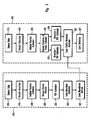
- FIG 2 is a block diagram of the functional components of a traffic monitoring system, in accordance with the preferred embodiment of the present invention.
- Traffic monitoring system 200 is depicted as being comprised of a sensor 110 which is illustrated as being comprised of a transceiver 202 which is further comprised of a transmitter 204 and a receiver 206.
- Transmitter 204 transmits an electromagnetic signal of a known power level toward traffic lanes 120-128 ( Figure 1 ) across a field of view 114 ( Figure 1 ).
- Receiver 206 receives a reflected power corresponding to a portion of the electromagnetic signal as reflected from each of the vehicles passing therethrough.
- Transmitter 204 and receiver 206 operate in concert with processor 208 to transmit the electromagnetic signal of a known power and measure a reflected power corresponding to the presence of vehicles passing therethrough.
- Processor 208 makes the processed data available to other elements of a traffic monitoring system such as a traffic controller system 210 and traffic management system 212.
- Figure 3 is a block diagram of the processing including the method for dynamically defining traffic lanes occurring within processor 208.
- Figure 3 depicts a flow diagram 310 for defining the lane boundaries and a flow diagram 312 for further refining the processing by determining a lane direction.
- sensor data 314 is received from transceiver 202 and is processed in a vehicle detection step 316 which determines the presence of a vehicle for contribution to the analysis of dynamic traffic lane definition.
- the detection algorithm starts by using the sensor data as input and then uses a Fourier transform to convert the time domain signal into the frequency domain.
- each Fourier transform bin shows the amount of energy the received signal contains at a particular frequency, and since range is proportional to frequency the Fourier transform magnitude represents the amount of energy received versus range. Vehicles reflect much more energy than the road or surrounding background and, therefore, their bright reflection shows up as a large spike in the magnitude of the Fourier transform.
- a detection threshold is set and when a Fourier transform magnitude exceeds the threshold, a vehicle detection occurs.
- a vehicle's position is estimated in a step 318 as calculated from the sensor data received above.
- the vehicle's position is estimated as the bin in which the peak of the Fourier transform is found.
- the vehicle's position is recorded in a step 320 with the vehicle's position measurement being recorded and contributing to the vehicle position probability density function (PDF) as estimated in the step 322.
- PDF vehicle position probability density function
- the vehicle position PDF represents the probability that a vehicle will be located at any range and reveals the lane locations on the road.
- the probability density function estimates a vehicle's position in a step 324 and facilitates the definition of lane boundaries in a step 325 within the system.
- the lane boundary estimation of the present invention uses the vehicle position PDF to estimate the location of traffic lane boundaries.
- the peaks of the PDF represent the center of each lane and the low spots (or valleys) of the PDF represent the lane boundaries (or regions where cars don't drive).
- the lane boundaries are set to be the low spots (or valleys) between peaks. There is not necessarily a valley before the first peak or after the last peak, therefore, a decision rule must be applied to set the two outside boundaries. Because of experience with the system a fixed distance from the outside peaks was typically used for the outside boundaries. These outside boundaries represent the edge of the road.
- Each range bin represents a slightly different position on the corresponding lane on the road, and each defined lane is comprised of multiple range bins.
- lane directionality is determined by utilizing sensor data. 314 and further employing vehicle detection step 316 and vehicle position estimating step 318.
- vehicle direction of travel is found by generating a first direction PDF estimation in a step 322 and a second direction PDF estimator in a step 324.
- a separate PDF for each direction of traffic flow is determined and then each of these PDFs is used, in conjunction with the lane boundary information in a step 325 to assign a traffic flow direction to each lane in a step 326.
- the information about the vehicle position from the vehicle position estimator
- the raw data are used.
- the radar is preferably not mounted precisely perpendicular to the road. It is mounted off perpendicular, pointing slightly into the direction of travel of the nearest lane (to the left if standing behind the radar facing the road) by a few degrees.
- the vehicle direction of travel is determined by tracking the Fourier transform phase while the vehicle is in the radar beam. Many measurements are made while the car is in the radar beam. After the car has left the beam, the consecutive phase measurements are phase unwrapped to produce a curve that is approximately quadratic in shape and shows evidence of vehicle travel direction.
- a vehicle entering the radar beam from the left will produce a curve similar to curve 340 of Figure 4 with the left end of the curve being higher than the right end. This occurs because with the radar turned a few degrees the vehicle spends more time, while in the radar beam, approaching the radar sensor than leaving the sensor. Likewise, a vehicle entering from the right will produce a curve as in curve 350 of Figure 4 with the right end of the curve being higher than the left.
- the vehicle position and lane boundaries are used to determine which lane the vehicle is in. The direction of traffic flow can then be estimated by using the direction PDF estimates to determine which direction of flow is most probable in each lane.
- Figure 5 depicts a side-fired deployment of a sensor 110, in accordance with the present invention. While sensors may be deployed in a number of setups, one preferred implementation is a side fire or perpendicular configuration.
- a roadside sensor 110 is depicted as having a field of view 114 spread across multiple lanes of traffic.
- the field of view is partitioned into a plurality of bins 400, each of which represents a distance or range such that a lane may be comprised of a plurality of bins which provide us a smaller and more improved granularity of statistical bins into which specific position may be allocated.
- Figure 6 depicts a statistical plotting or histogram of the positions of the exemplary data, in accordance with the processing methods of the present invention.
- range bins may be partitioned into widths of approximately two meters, while traffic lanes are approximately four meters in width. Such a granularity dictates that statistical lane information may be derived from a plurality of bins.
- a sensor's transmitted signal reflects off a vehicle back to the sensor when a vehicle passes through the field of view.
- the signal reflected off the vehicles is assigned to a bin having the corresponding reflected signal parameters and shows up as an energy measurement in the range bin representing the vehicle's position.
- the number of vehicles in each bin is counted with the count incremented when an additional vehicle is detected the count and assigned to that bin.
- a histogram of the bin count represents a PDF of vehicle position on the road. The histogram of position measurements identifies where vehicles are most probable to be and where the traffic lanes on the roadway should be defined.
- lanes 240 derive their specific lane positions by setting the lane boundaries between the peaks according to detection theory.
- FIG. 6 further depicts two separate peaks located within lane 250. Such a multiplicity denotes that lane 250 is used by vehicles traveling in both directions, mainly a turning lane located between two pairs of lanes facilitating vehicular traffic in opposite directions.
- X1 represents a random variable describing the position of vehicles traveling in lane 1.
- X2, X3, ..., and XN represent the random variables describing the position of vehicles traveling in lanes 2 through N.
- P x1 (x) be the probability distribution of X1, where x represents the vehicle position and can take on any value in the range of position measurements available to the sensor.
- the random variable that is available for estimation by a traffic sensor is the sum of the random variables for all lanes visible to the sensor.
- Y represent this random variable
- FIG. 7 depicts a typical distribution of an estimate of PDF of Y denoted by P ⁇ Y ( x ). Based on the estimated PDF of Y, an estimate can be derived for the PDFs of X1, through XN, that will be denoted by P ⁇ X 1 ( x ), through P ⁇ XN (x). For example, one exemplary method of doing this would be to combine several Gaussian distributions that are weighted and positioned proportional to the height and location of the peaks in P Y (x). If direction of travel information is available from the sensor, then this information can be used to distinguish sensor data from lanes of opposing direction thus simplifying the individual lane PDF estimation problem.
- the estimated PDFs P ⁇ X1 ( x ), through P ⁇ XN ( x ) can be used to calculate lane boundaries.
- One approach in calculating the lane boundaries is to use classic decision theory. By way of example and not limitation, an approach that minimizes average cost between two lanes is presented. In this approach, the PDF of each lane is compared to the probability that a vehicle is in each lane and to the cost of misclassification. This analysis produces the lane boundaries. Using these boundaries, the sensor's vehicle position measurement can be converted to a lane classification. For example, if the lane boundary is set at 10 then the vehicle will be said to be in lane 1 if x ⁇ 10 and will be said to be in lane 2 if x> 10.
- the Bayes Detector will minimize the average cost of misclassification. Let C 21 be the cost associated with classifying a vehicle in lane 2 when it is really in lane 1. Similarly, C 12 is the cost of classifying a vehicle in lane 1 when it is in lane 2. We assume there is no cost for a vehicle correctly classified. The Bayes Detector will give the minimum average cost and states that for a vehicle in lane 1: P X ⁇ 1 x P X ⁇ 2 x > p o ⁇ C 21 q o ⁇ C 12 .
- p o is the probability that the vehicle is in lane 1
- q o is the probability that the vehicle is in lane 2.
- p o and q o are based solely on past traffic information and not the current sensor measurement.
- p o and q o could be estimated from the original estimated PDF, P ⁇ Y ( x ), or a probability could be assumed. For example, if we know there is equal traffic in each lane then p o and q o should be set to 0.5. If we assume 80% of the traffic is in lane 1 then p o should be set to 0.8 and q o should be set to 0.2. After initial lane boundaries are assigned, vehicle counts in each lane can be used to estimate p o , and q o .
- the lane boundary is the value of x
- the boundary between two adjacent lanes can be calculated without considering the other lanes. For example, consider a roadway with three lanes. The boundary between lane 1 and lane 2 can be found using the statistical method described above (ignoring lane 3). The boundary between lane 2 and lane 3 can also be found using the same method (ignoring lane 1). The outside boundary of the outside lanes should be set based on the PDF of that lane alone. For example, the outside lane boundary can be set such that the probability a vehicle will lie outside the boundary is below a designated percentage.
- lane position algorithms have the ability to update lane boundaries.
- One example would be to have the current set of statistics averaged into the past statistics with a small weight given to older position statistics and greater weight to more recent statistics.
- the overall statistics will change to reflect the current situation in an amount of time dictated by how much the current set of data is weighted.
- Figure 8 illustrates a histogram of vehicle position measurement from data collected with the present invention.
- Each of the three peaks, 700, 702 and 704 represents the center of each calculated lane depicting a concentration of detected vehicles. Centered about probability concentration peaks 700, 702 and 704 are lane boundaries 706-712.
Landscapes
- Physics & Mathematics (AREA)
- General Physics & Mathematics (AREA)
- Chemical & Material Sciences (AREA)
- Analytical Chemistry (AREA)
- Traffic Control Systems (AREA)
- Radar Systems Or Details Thereof (AREA)
- Train Traffic Observation, Control, And Security (AREA)
- Length Measuring Devices With Unspecified Measuring Means (AREA)
Claims (39)
- Procédé pour définir des voies de circulation (120, 122, 124, 126, 128) dans un système de surveillance de circulation (100) comportant un capteur (110), comprenant les étapes consistant à :a. pour une pluralité pouvant être sélectionnée de véhicules,i. détecter chaque véhicule de ladite pluralité pouvant être sélectionnée de véhicules présent à l'intérieur d'un champ de vue (114) dudit capteur (110) ;ii. estimer une position de chaque dit véhicule de ladite pluralité pouvant être sélectionnée de véhicules ;iii. enregistrer ladite position de chaque dit véhicule de ladite pluralité pouvant être sélectionnée de véhicules ;b. générer une estimation de fonction de densité de probabilité à partir de chaque dite position de chaque dit véhicule de ladite pluralité pouvant être sélectionnée de véhicules ; etc. définir lesdites voies de circulation (120, 122, 124, 126, 128) à l'intérieur dudit système de surveillance de circulation (100) à partir de ladite estimation de fonction de densité de probabilité,
- Procédé selon la revendication 1, dans lequel ladite étape consistant à détecter chaque véhicule de ladite pluralité pouvant être sélectionnée de véhicules comprend les étapes consistant à :a. transmettre à partir dudit capteur (110) un signal électromagnétique d'une puissance connue vers lesdites voies de circulation (120, 122, 124, 126, 128) ; etb. mesurer audit capteur une puissance réfléchie correspondant à une partie (118) dudit signal électromagnétique tel qu'il est réfléchi à partir de chaque véhicule de ladite pluralité pouvant être sélectionnée de véhicules.
- Procédé selon la revendication 1, dans lequel ladite étape consistant à estimer une position comprend l'étape consistant à :a. segmenter ledit champ de vue (114) dudit capteur en cellules de distance (400) dans lequel chacune desdites voies de circulation (120, 122, 124, 126, 128) comprend une pluralité de cellules de distance (400) possédant chacune une distance de puissance reçue associée à celle-ci etb. attribuer ladite position de chaque dit véhicule de ladite pluralité pouvant être sélectionnée de véhicules à une cellule correspondante desdites cellules de distance (400) lorsque ladite puissance réfléchie à partir de chaque véhicule de ladite pluralité pouvant être sélectionnée de véhicules correspond à ladite distance de puissance réfléchie de ladite cellule correspondante de ladite pluralité de cellules de distance (400).
- Procédé selon la revendication 3, dans lequel ladite étape consistant à générer une fonction de densité de probabilité comprend l'étape consistant à :a. générer un histogramme desdites positions à l'intérieur de ladite pluralité de cellules de distance (400).
- Procédé selon la revendication 4, dans lequel ladite étape consistant à définir lesdites voies de circulation (120, 122, 124, 126, 128) comprend les étapes consistant à :a. identifier des pointes de probabilité (700, 702, 704) sur ledit histogramme desdites positions ; etb. définir des frontières (706, 708, 710, 712) autour de chacune desdites pointes de probabilité (700, 702, 704), lesdites frontières (706, 708, 710, 712) autour de chacune desdites pointes de probabilité (700, 702, 704) représentant une desdites voies de circulation (120, 122, 124, 126, 128) entre celles-ci.
- Procédé selon la revendication 1, dans lequel ladite étape consistant à générer une estimation de fonction de densité de probabilité comprend en outre l'étape consistant à :a. pondérer pour augmenter l'importance statistique des positions plus récentes de chacune desdites positions de chaque véhicule de ladite pluralité pouvant être sélectionnée de véhicules par rapport aux anciennes positions de chacune desdites positions.
- Procédé selon la revendication 1, comprenant en outre les étapes consistant à :a. attribuer une direction de flux de circulation à ladite position de chaque dit véhicule de ladite pluralité pouvant être sélectionnée de véhicules ;b. enregistrer ladite direction de flux de circulation à ladite position de chaque dit véhicule de ladite pluralité pouvant être sélectionnée de véhicules ;c. générer des estimations de fonction de densité de probabilité pour chacune desdites directions de flux de circulation ; etd. attribuer lesdites directions de flux de circulation auxdites voies de circulation (120, 122, 124, 126, 128).
- Procédé selon la revendication 1, dans lequel le procédé est destiné à configurer le système de surveillance de circulation (100) pour surveiller des voies de circulation (120, 122, 124, 126, 128), et dans lequel :ladite étape consistant à détecter comprend l'étape consistant à détecter la présence d'un ou de multiples véhicules à l'intérieur du champ de vue (114) du capteur (110) en utilisant un signal électromagnétique d'une puissance connue ;ladite étape consistant à estimer comprend l'étape consistant à estimer une position d'au moins une partie du ou des multiples véhicules détectés ;ladite étape consistant à enregistrer comprend l'étape consistant à enregistrer la position estimée pour au moins un véhicule détecté ;ladite étape consistant à générer comprend l'étape consistant à générer un histogramme à partir de quelconques positions estimées enregistrées de véhicules détectés ; etladite étape consistant à définir comprend l'étape consistant à définir les voies de circulation (120, 122, 124, 126, 128) à partir de l'histogramme.
- Procédé selon la revendication 8, dans lequel l'étape consistant à détecter la présence d'un ou de multiples véhicules à l'intérieur d'un champ de vue (114) du capteur (110) comprend les étapes consistant à :transmettre le signal électromagnétique d'une puissance connue vers les voies de circulation (120, 122, 124, 126, 128) ; etmesurer une puissance réfléchie correspondant à une partie (118) du signal électromagnétique transmis réfléchi à partir d'un objet à l'intérieur du champ de vue (114) du capteur (110).
- Procédé selon la revendication 8, dans lequel l'étape consistant à estimer une position d'au moins une partie du ou des multiples véhicules détectés comprend les étapes consistant à :segmenter le champ de vue (114) du capteur en cellules de distance (400), chaque cellule de distance (400) comportant une cellule de distance réfléchie associée ; etattribuer la position de chacune de l'au moins une partie du ou des multiples véhicules détectés à une cellule correspondante des cellules de distance (400), dans lequel un véhicule est attribué à une cellule de distance (400) lorsque la puissance réfléchie pour le véhicule correspond à la distance de puissance réfléchie pour la cellule de distance (400).
- Procédé selon la revendication 10, dans lequel l'étape consistant à attribuer la position de chacune de l'au moins une partie du ou des multiples véhicules détectés à une cellule correspondante des cellules de distance (400) comprend une étape consistant à incrémenter le compte pour une cellule de distance (400) lorsqu'un véhicule est attribué à la cellule de distance (400).
- Procédé selon la revendication 8, dans lequel l'étape consistant à définir les voies de circulation (120, 122, 124, 126, 128) comprend les étapes consistant à :identifier une pointe (700, 702, 704) sur l'histogramme ; etdéfinir une frontière (706, 708, 710, 712) autour de la pointe (700, 702, 704), la frontière (706, 708, 710, 712) représentant une voie de circulation (120, 122, 124, 126, 128).
- Procédé selon la revendication 8, dans lequel l'étape consistant à définir des voies de circulation (120, 122, 124, 126, 128) à partir de l'histogramme comprend une étape consistant à définir les voies de circulation (120, 122, 124, 126, 128) à partir de l'histogramme après avoir détecté la présence d'au moins une partie d'une pluralité de véhicules présents à l'intérieur d'un champ de vue (114) du capteur (110).
- Capteur (110) pour définir des voies de circulation (120, 122, 124, 126, 128) dans un système de surveillance de circulation (100), comprenant :a. un émetteur-récepteur (202) pour détecter chaque véhicule d'une pluralité pouvant être sélectionnée de véhicules présent à l'intérieur d'un champ de vue (114) dudit émetteur-récepteur (202) ; etb. un processeur (208) comprenant des instructions exécutables pour réaliser les étapes consistant à :i. estimer une position de chaque dit véhicule de ladite pluralité pouvant être sélectionnée de véhicules ;ii. enregistrer ladite position estimée de chaque dit véhicule de ladite pluralité pouvant être sélectionnée de véhicules ; pour une pluralité pouvant être sélectionnée de véhicules ;iii. générer une estimation de fonction de densité de probabilité à partir de chacune desdites positions enregistrées de chaque dit véhicule de ladite pluralité pouvant être sélectionnée de véhicules ; etiv. définir lesdites voies de circulation (120, 122, 124, 126, 128) à l'intérieur dudit système de surveillance de circulation (100) à partir de ladite estimation de fonction de densité de probabilité.
- Capteur (110) selon la revendication 14, dans lequel ledit émetteur-récepteur (202) comprend :a. un émetteur (204) pour transmettre un signal électromagnétique d'une puissance connue vers lesdites voies de circulation (120, 122, 124, 126, 128) ; etb. un récepteur (206) pour recevoir une puissance réfléchie correspondant à une partie (118) dudit signal électromagnétique tel qu'il est réfléchi à partir de chaque véhicule de ladite pluralité pouvant être sélectionnée de véhicules.
- Capteur (110) selon la revendication 14, dans lequel ledit processeur (208) comprend en outre des instructions exécutables pour réaliser les étapes consistant à :a. segmenter ledit champ de vue (114) dudit capteur en cellules de distance (400) dans lequel chacune desdites voies de circulation (120, 122, 124, 126, 128) comprend une pluralité de cellules de distance (400) possédant chacune une distance de puissance reçue associée à celle-ci ;
etb. attribuer ladite position de chaque dit véhicule de ladite pluralité pouvant être sélectionnée de véhicules à une cellule correspondante desdites cellules de distance (400) lorsque ladite puissance réfléchie à partir de chaque véhicule de ladite pluralité pouvant être sélectionnée de véhicules correspond à ladite distance de puissance réfléchie de ladite cellule correspondante de ladite pluralité de cellules de distance (400). - Capteur (110) selon la revendication 16, dans lequel ledit processeur (208) comprend en outre des instructions exécutables pour réaliser l'étape consistant à :a. générer un histogramme desdites positions à l'intérieur de ladite pluralité de cellules de distance (400).
- Capteur (110) selon la revendication 17, dans lequel lesdites instructions exécutables pour définir lesdites voies de circulation (120, 122, 124, 126, 128) comprennent en outre des instructions exécutables pour réaliser les étapes consistant à :a. identifier des pointes de probabilité (700, 702, 704) sur ledit histogramme desdites positions ;b. définir des frontières (706, 708, 710, 712) autour de chacune desdites pointes de probabilité (700, 702, 704), lesdites frontières (706, 708, 710, 712) autour de chacune desdites pointes de probabilité (700, 702, 704) représentant une desdites voies de circulation (120, 122, 124, 126, 128) entre celles-ci.
- Capteur (110) selon la revendication 14, dans lequel lesdites instructions exécutables pour réaliser les étapes consistant à générer une estimation de fonction de densité de probabilité comprennent en outre des instructions exécutables pour réaliser l'étape consistant à :a. pondérer pour augmenter l'importance statistique des positions plus récentes de chacune desdites positions de chaque véhicule de ladite pluralité pouvant être sélectionnée de véhicules par rapport aux anciennes positions de chacune desdites positions.
- Capteur (110) selon la revendication 14, comprenant en outre des instructions exécutables pour réaliser les étapes consistant à :a. attribuer une direction de flux de circulation à ladite position de chaque dit véhicule de ladite pluralité pouvant être sélectionnée de véhicules ;b. enregistrer ladite direction de flux de circulation à ladite position de chaque dit véhicule de ladite pluralité pouvant être sélectionnée de véhicules ;c. générer des estimations de fonction de densité de probabilité pour chacune desdites directions de flux de circulation ; etd. attribuer lesdites directions de flux de circulation auxdites voies de circulation (120, 122, 124, 126, 128).
- Système de détection (100) comprenant un capteur (110) selon la revendication 14, pour définir des voies de circulation (120, 122, 124, 126, 128) pour une surveillance suivante, dans lequel :l'émetteur-récepteur (202) est destiné à détecter la présence d'un ou de multiples véhicules à l'intérieur d'un champ de vue (114) du capteur (110) en utilisant un signal électromagnétique d'une puissance connue ;le processeur comprend un ou de multiples processors (208) et un ou de multiples supports assimilables par ordinateur comportant, stockées sur ceux-ci, des instructions exécutables par ordinateur qui, lorsqu'elles sont exécutées sur le ou les multiples processors (208), font en sorte que le système de détection (100) réalise les étapes consistant à :estimer une position d'au moins une partie du ou des multiples véhicules détectés ;enregistrer la position estimée pour au moins un véhicule détecté ;générer un histogramme à partir de quelconques positions estimées enregistrées de véhicules détectés ; etdéfinir les voies de circulation (120, 122, 124, 126, 128) à partir de l'histogramme.
- Système de détection (100) selon la revendication 21, dans lequel l'émetteur-récepteur (202) comprend :un émetteur (204) pour transmettre le signal électromagnétique d'une puissance connue vers les voies de circulation (120, 122, 124, 126, 128) ; etun récepteur (206) pour recevoir une puissance réfléchie correspondant à une partie (118) du signal électromagnétique transmis tel qu'il est réfléchi à partir d'un objet à l'intérieur du champ de vue (114) de l'émetteur-récepteur (202).
- Système (100) selon la revendication 21, dans lequel les instructions exécutables par ordinateur qui, lorsqu'elles sont exécutées sur le ou les multiples processors (208), font en sorte que le système de détection (100) estime une position d'au moins une partie du ou des multiples véhicules détectés, comprennent des instructions exécutables par ordinateur qui, lorsqu'elles sont exécutées sur le ou les multiples processeurs (208), font en sorte que le système de détection (100) réalise les étapes consistant à :segmenter le champ de vue (114) de l'émetteur-récepteur (202) en cellules de distance (4100), chaque cellule de distance (400) comportant une cellule de distance réfléchie associée ; etattribuer la position de chacune de l'au moins une partie du ou des multiples véhicules détectés à une cellule correspondante des cellules de distance (400), dans lequel un véhicule est attribué à une cellule de distance (400) lorsque la puissance réfléchie pour le véhicule correspond à la distance de puissance réfléchie pour la cellule de distance (400).
- Système (100) selon la revendication 23, dans lequel les instructions exécutables par ordinateur qui, lorsqu'elles sont exécutées sur le ou les multiples processors (208), font en sorte que le système de détection (100) attribue la position de chacune de l'au moins une partie du ou des multiples véhicules détectés à une cellule correspondante des cellules de distance (400), comprennent des instructions exécutables par ordinateur qui, lorsqu'elles sont exécutées sur le ou les multiples processors (208), font en sorte que le système de détection (100) incrémente le compte pour une cellule de distance (400) lorsqu'un véhicule est attribué à la cellule de distance (400).
- Système (100) selon la revendication 21, dans lequel des instructions exécutables par ordinateur qui, lorsqu'elles sont exécutées sur le ou les multiples processors (208), font en sorte que le système de détection (100) définisse les voies de circulation (120, 122, 124, 126, 128) à partir de l'histogramme, comprennent des instructions exécutables par ordinateur qui, lorsqu'elles sont exécutées sur le ou les multiples processors (208), font en sorte que le système de détection (100) réalise les étapes consistant à :identifier une pointe (700, 702, 704) sur l'histogramme ; etdéfinir une frontière (706, 708, 710, 712) autour de la pointe (700, 702, 704), la frontière (706, 708, 710, 712) représentant une voie de circulation (120, 122, 12 t, 126, 128).
- Système (100) selon la revendication 21, dans lequel des instructions exécutables par ordinateur qui, lorsqu'elles sont exécutées sur le ou les multiples processors (208), font en sorte que le système de détection (100) définisse les voies de circulation (120, 122, 124, 126, 128) à partir de l'histogramme, comprennent des instructions exécutables par ordinateur qui, lorsqu'elles sont exécutées sur le ou les multiples processors (208), font en sorte que le système de détection (100) définisse les voies de circulation (120, 122, 124, 126, 128) à partir de l'histogramme après avoir détecté la présence de l'au moins une partie de la pluralité de véhicules présents à l'intérieur d'un champ de vue (114) de l'émetteur-récepteur (202).
- Support assimilable par ordinateur comportant, sur celui-ci, des instructions exécutables par ordinateur destinées à être exécutées par un processeur d'un capteur de surveillance de circulation (110), ledit capteur (110) comprenant un émetteur-récepteur (202), pour réaliser les étapes consistant à :a. pour une pluralité pouvant être sélectionnée de véhicules,i. détecter chaque véhicule de ladite pluralité pouvant être sélectionnée de véhicules présent à l'intérieur d'un champ de vue (114) dudit capteur (110) ;ii. estimer une position de chaque dit véhicule de ladite pluralité pouvant être sélectionnée de véhicules ;iii. enregistrer ladite position de chaque dit véhicule de ladite pluralité pouvant être sélectionnée de véhicules ;b. générer une estimation de fonction de densité de probabilité à partir de chaque dite position de chaque dit véhicule de ladite pluralité pouvant être sélectionnée de véhicules ; etc. définir lesdites voies de circulation (120, 122, 124, 126, 128) à l'intérieur dudit système de surveillance de circulation (100) à partir de ladite estimation de fonction de densité de probabilité.
- Support assimilable par ordinateur selon la revendication 27, dans lequel lesdites instructions exécutables par ordinateur pour réaliser les étapes consistant à détecter chaque véhicule de ladite pluralité pouvant être sélectionnée de véhicules comprennent des instructions exécutables par ordinateur pour réaliser les étapes consistant à :a. transmettre à partir dudit capteur (110) un signal électromagnétique d'une puissance connue vers lesdites voies de circulation (120, 122, 124, 126, 128) ; etb. mesurer audit capteur (110) une puissance réfléchie correspondant à une partie (118) dudit signal électromagnétique tel qu'il est réfléchi à partir de chaque véhicule de ladite pluralité pouvant être sélectionnée de véhicules.
- Support assimilable par ordinateur selon la revendication 27, dans lequel des instructions exécutables par ordinateur pour réaliser les étapes consistant à estimer une position comprennent des instructions exécutables par ordinateur pour réaliser les étapes consistant à :a. segmenter ledit champ de vue (114) dudit capteur en cellules de distance (400), dans lequel chacune desdites voies de circulation (120, 122, 124, 126, 128) comprend une pluralité de cellules de distance (400) possédant chacune une distance de puissance reçue associée à celle-ci, etb. attribuer ladite position de chaque dit véhicule de ladite pluralité pouvant être sélectionnée de véhicules à une cellule correspondante desdites cellules de distance (400) lorsque ladite puissance réfléchie à partir de chaque véhicule de ladite pluralité pouvant être sélectionnée de véhicules correspond à ladite distance de puissance réfléchie de ladite cellule correspondante de ladite pluralité de cellules de distance (400).
- Support assimilable par ordinateur selon la revendication 29, dans lequel lesdites instructions exécutables par ordinateur pour réaliser l'étape consistant à générer une fonction de densité de probabilité comprennent des instructions exécutables par ordinateur pour réaliser l'étape consistant à :a. générer un histogramme desdites positions à l'intérieur de ladite pluralité de cellules de distance (400).
- Support assimilable par ordinateur selon la revendication 30, dans lequel lesdites instructions exécutables par ordinateur pour réaliser l'étape consistant à définir lesdites voies de circulation (120, 122, 124, 126, 128) comprennent des instructions exécutables par ordinateur pour réaliser les étapes consistant à :a. identifier des pointes de probabilité (700, 702, 704) sur ledit histogramme desdites positions ; etb. définir des frontières (706, 708, 710, 712) autour de chacune desdites pointes de probabilité (700, 702, 704), lesdites frontières (706, 708, 710, 712) autour de chacune desdites pointes de probabilité (700, 702, 704) représentant une desdites voies de circulation (120, 122, 124, 125, 128) entre celles-ci.
- Support assimilable par ordinateur selon la revendication 27, dans lequel lesdites instructions exécutables par ordinateur pour réaliser l'étape consistant à générer une estimation de fonction de densité de probabilité comprennent en outre des instructions exécutables par ordinateur pour réaliser l'étape consistant à :a. pondérer pour augmenter l'importance statistique des positions plus récentes de chacune desdites positions de chaque véhicule de ladite pluralité pouvant être sélectionnée de véhicules par rapport aux anciennes positions de chacune desdites positions.
- Support assimilable par ordinateur selon la revendication 27, dans lequel lesdites instructions exécutables par ordinateur comprennent en outre des instructions exécutables par ordinateur pour réaliser les étapes consistant à :a. attribuer une direction de flux de circulation à ladite position de chaque dit véhicule de ladite pluralité pouvant être sélectionnée de véhicules ;b. enregistrer ladite direction de flux de circulation à ladite position de chaque dit véhicule de ladite pluralité pouvant être sélectionnée de véhicules ;c. générer des estimations de fonction de densité de probabilité pour chacune desdites directions de flux de circulation ; etd. attribuer lesdites directions de flux de circulation auxdites voies de circulation (120, 122, 124, 126, 128).
- Support assimilable par ordinateur selon la revendication 27, dans lequel ledit processeur comprend un ou de multiples processors (208) d'un système de surveillance de circulation (100), et dans lequel l'exécution des instructions assimilables par ordinateur fait en sorte que le système de surveillance de circulation (100) réalise un procédé pour configurer le système de surveillance de circulation (100) pour surveiller par la suite des voies de circulation (120, 122, 124, 126, 128), et dans lequel :ladite étape consistant à détecter comprend l'étape consistant à détecter la présence d'un ou de multiples véhicules à l'intérieur d'un champ de vue (114) du capteur (110) en utilisant un signal électromagnétique d'une puissance connue ;ladite étape consistant à estimer comprend l'étape consistant à estimer une position d'au moins une partie du ou des multiples véhicules détectés ;ladite étape consistant à enregistrer comprend l'étape consistant à enregistrer la position estimée pour au moins un véhicule détecté ;ladite étape consistant à générer comprend l'étape consistant à générer un histogramme à partir de quelconques positions estimées enregistrées de véhicules détectés ; etladite étape consistant à définir comprend l'étape consistant à définir les voies de circulation (120, 122, 124, 126, 128) à partir de l'histogramme.
- Support assimilable par ordinateur selon la revendication 34, dans lequel des instructions exécutables par ordinateur qui, lorsqu'elles sont exécutées, font en sorte que le système de surveillance de circulation (100) détecte la présence d'un ou de multiples véhicules à l'intérieur d'un champ de vue (114) du capteur (110), comprennent des instructions exécutables par ordinateur qui, lorsqu'elles sont exécutées, font en sorte que le système de surveillance de circulation (100) réalise les étapes consistant à :transmettre le signal électromagnétique d'une puissance connue vers les voies de circulation (120, 122, 124, 126, 128) ; etmesurer une puissance réfléchie correspondant à une partie (118) du signal électromagnétique transmis réfléchi à partir d'un objet à l'intérieur du champ de vue (114) du capteur (110).
- Support assimilable par ordinateur selon la revendication 34, dans lequel des instructions exécutables par ordinateur qui, lorsqu'elles sont exécutées, font en sorte que le système de surveillance de circulation (100) estime une position d'au moins une partie du ou des multiples véhicules détectés, comprennent des instructions exécutables par ordinateur qui, lorsqu'elles sont exécutées, font en sorte que le système de surveillance de circulation (100) réalise les étapes consistant à ;segmenter le champ de vue (114) du capteur (110) en cellules de distance (400), chaque cellule de distance (400) comportant une cellule de distance réfléchie associée ; etattribuer la position de chacune de l'au moins une partie du ou des multiples véhicules détectés à une cellule correspondante des cellules de distance (400), dans lequel un véhicule est attribué à une cellule de distance (400) lorsque la puissance réfléchie pour le véhicule correspond à la distance de puissance réfléchie pour la cellule de distance (400).
- Support assimilable par ordinateur selon la revendication 36, dans lequel des instructions exécutables par ordinateur qui, lorsqu'elles sont exécutées, font en sorte que le système de surveillance de circulation (100) attribue la position de chacune de l'au moins une partie du ou des multiples véhicules détectés à une cellule correspondante des cellules de distance (400), comprennent des instructions exécutables par ordinateur qui, lorsqu'elles sont exécutées, font en sorte que le système de surveillance de circulation (100) incrémente le compte pour une cellule de distance (400) lorsqu'un véhicule est attribué à la cellule de distance (400).
- Support assimilable par ordinateur selon la revendication 34, dans lequel des instructions exécutables par ordinateur qui, lorsqu'elles sont exécutées, font en sorte que le système de surveillance de circulation (100) définisse les voies de circulation (120, 122, 124, 126, 128) à partir de l'histogramme, comprennent des instructions exécutables par ordinateur qui, lorsqu'elles sont exécutées, font en sorte que le système de surveillance de circulation (100) réalise les étapes consistant à :identifier une pointe (700, 702, 704) sur l'histogramme ; etdéfinir une frontière (706, 708, 710, 712) autour de la pointe (700, 702, 704), la frontière (706, 708, 710, 712) représentant une voie de circulation (120, 122, 121, 126, 128).
- Support assimilable par ordinateur selon la revendication 34, dans lequel des instructions exécutables par ordinateur qui, lorsqu'elles sont exécutées, font en sorte que le système de surveillance de circulation (100) définisse les voies de circulation (120, 122, 124, 126, 128) à partir de l'histogramme, comprennent des instructions exécutables par ordinateur qui, lorsqu'elles sont exécutées, font en sorte que le système de surveillance de circulation (100) définisse les voies de circulation (120, 122, 124, 126, 128) à partir de l'histogramme après avoir détecté la présence d'au moins une partie d'une pluralité de véhicules présents à l'intérieur d'un champ de vue (114) du capteur (110).
Applications Claiming Priority (3)
| Application Number | Priority Date | Filing Date | Title |
|---|---|---|---|
| US966146 | 2001-09-27 | ||
| US09/966,146 US6556916B2 (en) | 2001-09-27 | 2001-09-27 | System and method for identification of traffic lane positions |
| PCT/US2002/027682 WO2003027985A2 (fr) | 2001-09-27 | 2002-08-29 | Systeme et procede d'identification des positions des voies de circulation |
Publications (4)
| Publication Number | Publication Date |
|---|---|
| EP1435036A2 EP1435036A2 (fr) | 2004-07-07 |
| EP1435036A4 EP1435036A4 (fr) | 2006-05-03 |
| EP1435036B1 true EP1435036B1 (fr) | 2010-01-06 |
| EP1435036B8 EP1435036B8 (fr) | 2010-03-03 |
Family
ID=25510979
Family Applications (1)
| Application Number | Title | Priority Date | Filing Date |
|---|---|---|---|
| EP02775735A Expired - Lifetime EP1435036B8 (fr) | 2001-09-27 | 2002-08-29 | Systeme et procede d'identification des positions des voies de circulation |
Country Status (7)
| Country | Link |
|---|---|
| US (1) | US6556916B2 (fr) |
| EP (1) | EP1435036B8 (fr) |
| AT (1) | ATE454659T1 (fr) |
| AU (1) | AU2002341586A1 (fr) |
| CA (1) | CA2434756C (fr) |
| DE (1) | DE60235023D1 (fr) |
| WO (1) | WO2003027985A2 (fr) |
Cited By (10)
| Publication number | Priority date | Publication date | Assignee | Title |
|---|---|---|---|---|
| US8242476B2 (en) | 2005-12-19 | 2012-08-14 | Leddartech Inc. | LED object detection system and method combining complete reflection traces from individual narrow field-of-view channels |
| US8310655B2 (en) | 2007-12-21 | 2012-11-13 | Leddartech Inc. | Detection and ranging methods and systems |
| US8436748B2 (en) | 2007-06-18 | 2013-05-07 | Leddartech Inc. | Lighting system with traffic management capabilities |
| US8600656B2 (en) | 2007-06-18 | 2013-12-03 | Leddartech Inc. | Lighting system with driver assistance capabilities |
| US8723689B2 (en) | 2007-12-21 | 2014-05-13 | Leddartech Inc. | Parking management system and method using lighting system |
| US8842182B2 (en) | 2009-12-22 | 2014-09-23 | Leddartech Inc. | Active 3D monitoring system for traffic detection |
| US8908159B2 (en) | 2011-05-11 | 2014-12-09 | Leddartech Inc. | Multiple-field-of-view scannerless optical rangefinder in high ambient background light |
| US9235988B2 (en) | 2012-03-02 | 2016-01-12 | Leddartech Inc. | System and method for multipurpose traffic detection and characterization |
| US9378640B2 (en) | 2011-06-17 | 2016-06-28 | Leddartech Inc. | System and method for traffic side detection and characterization |
| US10731993B2 (en) | 2015-03-06 | 2020-08-04 | Here Global B.V. | Turn lane configuration |
Families Citing this family (75)
| Publication number | Priority date | Publication date | Assignee | Title |
|---|---|---|---|---|
| US6693557B2 (en) | 2001-09-27 | 2004-02-17 | Wavetronix Llc | Vehicular traffic sensor |
| JP2005513636A (ja) * | 2001-12-19 | 2005-05-12 | ログオブジェクト アクチェンゲゼルシャフト | 対象物の追跡、特に交通監視のための方法と装置 |
| US7409286B2 (en) * | 2002-06-24 | 2008-08-05 | Jorge Osvaldo Ambort | Application for diminishing or avoiding the unwanted effects of traffic congestion |
| US7426450B2 (en) * | 2003-01-10 | 2008-09-16 | Wavetronix, Llc | Systems and methods for monitoring speed |
| US7132959B2 (en) * | 2003-03-05 | 2006-11-07 | Diablo Controls, Inc. | Non-interfering vehicle detection |
| US7130745B2 (en) * | 2005-02-10 | 2006-10-31 | Toyota Technical Center Usa, Inc. | Vehicle collision warning system |
| US20060200303A1 (en) * | 2005-02-24 | 2006-09-07 | Fuentes Jorge S | The static or dynamic roadway travel time system to determine the path with least travel time between two places |
| US7454287B2 (en) * | 2005-07-18 | 2008-11-18 | Image Sensing Systems, Inc. | Method and apparatus for providing automatic lane calibration in a traffic sensor |
| US7558536B2 (en) * | 2005-07-18 | 2009-07-07 | EIS Electronic Integrated Systems, Inc. | Antenna/transceiver configuration in a traffic sensor |
| US7274307B2 (en) * | 2005-07-18 | 2007-09-25 | Pdk Technologies, Llc | Traffic light violation indicator |
| US7768427B2 (en) * | 2005-08-05 | 2010-08-03 | Image Sensign Systems, Inc. | Processor architecture for traffic sensor and method for obtaining and processing traffic data using same |
| DE102005039103A1 (de) * | 2005-08-18 | 2007-03-01 | Robert Bosch Gmbh | Verfahren für die Erfassung eines Verkehrsraums |
| US7474259B2 (en) * | 2005-09-13 | 2009-01-06 | Eis Electronic Integrated Systems Inc. | Traffic sensor and method for providing a stabilized signal |
| US8248272B2 (en) | 2005-10-31 | 2012-08-21 | Wavetronix | Detecting targets in roadway intersections |
| US7889097B1 (en) | 2005-12-19 | 2011-02-15 | Wavetronix Llc | Detecting targets in roadway intersections |
| US7573400B2 (en) * | 2005-10-31 | 2009-08-11 | Wavetronix, Llc | Systems and methods for configuring intersection detection zones |
| US8665113B2 (en) | 2005-10-31 | 2014-03-04 | Wavetronix Llc | Detecting roadway targets across beams including filtering computed positions |
| US7991542B2 (en) * | 2006-03-24 | 2011-08-02 | Wavetronix Llc | Monitoring signalized traffic flow |
| US7541943B2 (en) * | 2006-05-05 | 2009-06-02 | Eis Electronic Integrated Systems Inc. | Traffic sensor incorporating a video camera and method of operating same |
| US20080062009A1 (en) * | 2006-08-30 | 2008-03-13 | Marton Keith J | Method and system to improve traffic flow |
| US7501976B2 (en) * | 2006-11-07 | 2009-03-10 | Dan Manor | Monopulse traffic sensor and method |
| US9460619B2 (en) * | 2007-01-17 | 2016-10-04 | The Boeing Company | Methods and systems for controlling traffic flow |
| US20080243439A1 (en) * | 2007-03-28 | 2008-10-02 | Runkle Paul R | Sensor exploration and management through adaptive sensing framework |
| US20080243425A1 (en) * | 2007-03-28 | 2008-10-02 | Eliazar Austin I D | Tracking target objects through occlusions |
| US7990325B2 (en) * | 2007-05-18 | 2011-08-02 | Powerwave Technologies, Inc. | System and method for remote antenna positioning data acquisition |
| US20080291055A1 (en) * | 2007-05-23 | 2008-11-27 | Harrington Nathan J | Method and system for vehicle traffic monitoring based on the detection of a characteristic radio frequency |
| US7739030B2 (en) * | 2007-11-13 | 2010-06-15 | Desai Shitalkumar V | Relieving urban traffic congestion |
| US7884740B2 (en) * | 2008-03-28 | 2011-02-08 | National Chiao Tung University | Multi-lane vehicle detection apparatus |
| DE102008019375A1 (de) * | 2008-04-17 | 2009-12-03 | Siemens Aktiengesellschaft | Detektorsystem und Verfahren zur Ermittlung eines Belegungsstatus eines Fahrbahn-Seitenstreifens, Verkehrssteuerungssystem und Verkehrssteuerungsverfahren |
| US20100063714A1 (en) * | 2008-09-05 | 2010-03-11 | International Business Machines Corporation | method for determining traffic conditions |
| US8055445B2 (en) * | 2008-09-24 | 2011-11-08 | Delphi Technologies, Inc. | Probabilistic lane assignment method |
| US8116968B2 (en) * | 2008-12-23 | 2012-02-14 | National Chiao Tung University | Method for identification of traffic lane boundary |
| US20100272510A1 (en) * | 2009-04-24 | 2010-10-28 | LED Lane Light Inc. | Illuminated groove seals for pathways |
| DE102010050167B4 (de) * | 2010-10-30 | 2012-10-25 | Audi Ag | Verfahren und Vorrichtung zur Bestimmung eines plausiblen Fahrstreifens zur Führung eines Fahrzeugs sowie Kraftwagen |
| US9472097B2 (en) * | 2010-11-15 | 2016-10-18 | Image Sensing Systems, Inc. | Roadway sensing systems |
| EP2663971A1 (fr) * | 2010-11-15 | 2013-11-20 | Image Sensing Systems, Inc. | Système de détection de la circulation hybride et procédé associé |
| KR20120072020A (ko) * | 2010-12-23 | 2012-07-03 | 한국전자통신연구원 | 자율주행 시스템의 주행정보 인식 방법 및 장치 |
| CN102568189A (zh) * | 2010-12-30 | 2012-07-11 | 深圳富泰宏精密工业有限公司 | 智能交通系统 |
| US20130282264A1 (en) * | 2010-12-31 | 2013-10-24 | Edwin Bastiaensen | Systems and methods for obtaining and using traffic flow information |
| EP2659472A1 (fr) | 2010-12-31 | 2013-11-06 | Tomtom Belgium N.V. | Procédés et systèmes de navigation |
| US8452771B2 (en) | 2011-01-03 | 2013-05-28 | Honda Motor Co., Ltd. | Method for differentiating traffic data obtained from probe vehicles |
| US8723690B2 (en) * | 2011-01-26 | 2014-05-13 | International Business Machines Corporation | Systems and methods for road acoustics and road video-feed based traffic estimation and prediction |
| DE102011052218A1 (de) * | 2011-07-27 | 2013-01-31 | Jenoptik Robot Gmbh | Anhänger zur Verkehrsüberwachung |
| US8948954B1 (en) * | 2012-03-15 | 2015-02-03 | Google Inc. | Modifying vehicle behavior based on confidence in lane estimation |
| US9063548B1 (en) | 2012-12-19 | 2015-06-23 | Google Inc. | Use of previous detections for lane marker detection |
| US9081385B1 (en) | 2012-12-21 | 2015-07-14 | Google Inc. | Lane boundary detection using images |
| US9412271B2 (en) | 2013-01-30 | 2016-08-09 | Wavetronix Llc | Traffic flow through an intersection by reducing platoon interference |
| US9503706B2 (en) * | 2013-09-10 | 2016-11-22 | Xerox Corporation | Determining source lane of moving item merging into destination lane |
| CN103578280B (zh) * | 2013-10-12 | 2015-11-18 | 西安理工大学 | 基于物联网的车流量监测系统及车辆监测方法 |
| TWI534764B (zh) * | 2014-01-10 | 2016-05-21 | 財團法人工業技術研究院 | 車輛定位裝置與方法 |
| WO2016018936A1 (fr) | 2014-07-28 | 2016-02-04 | Econolite Group, Inc. | Contrôleur de signal de trafic auto-configurable |
| KR101573764B1 (ko) * | 2014-07-28 | 2015-12-02 | 현대모비스 주식회사 | 차량의 주행 차로 인식 시스템 및 방법 |
| CA2960123C (fr) | 2014-09-09 | 2021-04-13 | Leddartech Inc. | Discretisation de zone de detection |
| US10533863B2 (en) | 2014-10-10 | 2020-01-14 | Here Global B.V. | Apparatus and associated methods for use in lane-level mapping of road intersections |
| US9574387B2 (en) | 2014-11-21 | 2017-02-21 | The Chamberlain Group, Inc. | Alignment of obstacle detection components |
| US9721471B2 (en) | 2014-12-16 | 2017-08-01 | Here Global B.V. | Learning lanes from radar data |
| US10262213B2 (en) | 2014-12-16 | 2019-04-16 | Here Global B.V. | Learning lanes from vehicle probes |
| CN104933882A (zh) | 2015-05-20 | 2015-09-23 | 浙江吉利汽车研究院有限公司 | 一种交通路口驾驶辅助方法及系统 |
| US9903947B2 (en) * | 2015-08-10 | 2018-02-27 | Deere & Company | Boundary signal detection |
| US10672266B2 (en) * | 2016-01-05 | 2020-06-02 | TollSense, LLC | Systems and methods for monitoring roadways using magnetic signatures |
| US9934682B2 (en) * | 2016-01-05 | 2018-04-03 | TollSense, LLC | Systems and methods for monitoring roadways using magnetic signatures |
| US12403932B2 (en) * | 2016-06-21 | 2025-09-02 | Robert C. Brasher | Autonomous vehicle navigation of bypass merge lanes |
| US10048688B2 (en) * | 2016-06-24 | 2018-08-14 | Qualcomm Incorporated | Dynamic lane definition |
| US10102744B2 (en) | 2016-09-27 | 2018-10-16 | International Business Machines Corporation | Predictive traffic management using virtual lanes |
| US10379198B2 (en) * | 2017-04-06 | 2019-08-13 | International Business Machines Corporation | Determining positions of transducers for receiving and/or transmitting wave signals |
| GB2564882B (en) * | 2017-07-25 | 2022-04-13 | Red Fox Id Ltd | Apparatus and methods for assessing vehicles straddled between lanes |
| US10916125B2 (en) | 2018-07-30 | 2021-02-09 | Honda Motor Co., Ltd. | Systems and methods for cooperative smart lane selection |
| CN110796862B (zh) * | 2019-11-05 | 2021-09-07 | 西南交通大学 | 一种基于人工智能的高速公路交通状况检测系统及方法 |
| JP7416263B2 (ja) * | 2020-01-27 | 2024-01-17 | 日本電気株式会社 | 交通監視装置、システム、交通監視方法及びプログラム |
| US11379817B1 (en) | 2021-01-26 | 2022-07-05 | Ford Global Technologies, Llc | Smart toll application determining for various toll applications using V2X communications |
| US11676426B2 (en) * | 2021-03-19 | 2023-06-13 | Ford Global Technologies, Llc | Toll advertisement message road topologies |
| JP7540406B2 (ja) * | 2021-08-27 | 2024-08-27 | トヨタ自動車株式会社 | 自動車 |
| DE102022200970A1 (de) * | 2022-01-31 | 2023-08-03 | Robert Bosch Gesellschaft mit beschränkter Haftung | Verfahren zur Zuordnung von dynamischen Objekten zu Fahrspuren einer Straße |
| US20230408683A1 (en) * | 2022-06-19 | 2023-12-21 | Wavetronix Llc | Single radar system for multiple approaches |
| US20240230886A1 (en) * | 2022-06-19 | 2024-07-11 | Wavetronix Llc | Monitoring traffic in an intersection interior |
Family Cites Families (12)
| Publication number | Priority date | Publication date | Assignee | Title |
|---|---|---|---|---|
| US5448484A (en) | 1992-11-03 | 1995-09-05 | Bullock; Darcy M. | Neural network-based vehicle detection system and method |
| JPH08509103A (ja) | 1992-12-01 | 1996-09-24 | スーパーコンダクティング・コア・テクノロジーズ・インコーポレーテッド | 高温度超電導膜および強誘電性膜を含む同調可能マイクロ波装置 |
| US5793491A (en) | 1992-12-30 | 1998-08-11 | Schwartz Electro-Optics, Inc. | Intelligent vehicle highway system multi-lane sensor and method |
| US5748153A (en) | 1994-11-08 | 1998-05-05 | Northrop Grumman Corporation | Flared conductor-backed coplanar waveguide traveling wave antenna |
| JPH08204443A (ja) | 1995-01-27 | 1996-08-09 | Nippon Mektron Ltd | 受信用コプレーナ線路給電アクティブアンテナ |
| US5878367A (en) * | 1996-06-28 | 1999-03-02 | Northrop Grumman Corporation | Passive acoustic traffic monitoring system |
| US5798983A (en) | 1997-05-22 | 1998-08-25 | Kuhn; John Patrick | Acoustic sensor system for vehicle detection and multi-lane highway monitoring |
| US5949383A (en) | 1997-10-20 | 1999-09-07 | Ericsson Inc. | Compact antenna structures including baluns |
| CA2656141C (fr) | 1998-05-15 | 2012-02-07 | International Road Dynamics Inc. | Methode de commande automatique de dispositif de signalisation routiere |
| US6198437B1 (en) | 1998-07-09 | 2001-03-06 | The United States Of America As Represented By The Secretary Of The Air Force | Broadband patch/slot antenna |
| US6081226A (en) | 1998-07-10 | 2000-06-27 | Northrop Grumman Corporation | Multi-mode radar exciter |
| US6177885B1 (en) | 1998-11-03 | 2001-01-23 | Esco Electronics, Inc. | System and method for detecting traffic anomalies |
-
2001
- 2001-09-27 US US09/966,146 patent/US6556916B2/en not_active Expired - Lifetime
-
2002
- 2002-08-29 EP EP02775735A patent/EP1435036B8/fr not_active Expired - Lifetime
- 2002-08-29 AU AU2002341586A patent/AU2002341586A1/en not_active Abandoned
- 2002-08-29 CA CA2434756A patent/CA2434756C/fr not_active Expired - Lifetime
- 2002-08-29 AT AT02775735T patent/ATE454659T1/de not_active IP Right Cessation
- 2002-08-29 DE DE60235023T patent/DE60235023D1/de not_active Expired - Lifetime
- 2002-08-29 WO PCT/US2002/027682 patent/WO2003027985A2/fr not_active Ceased
Cited By (11)
| Publication number | Priority date | Publication date | Assignee | Title |
|---|---|---|---|---|
| US8242476B2 (en) | 2005-12-19 | 2012-08-14 | Leddartech Inc. | LED object detection system and method combining complete reflection traces from individual narrow field-of-view channels |
| US8436748B2 (en) | 2007-06-18 | 2013-05-07 | Leddartech Inc. | Lighting system with traffic management capabilities |
| US8600656B2 (en) | 2007-06-18 | 2013-12-03 | Leddartech Inc. | Lighting system with driver assistance capabilities |
| US8310655B2 (en) | 2007-12-21 | 2012-11-13 | Leddartech Inc. | Detection and ranging methods and systems |
| US8723689B2 (en) | 2007-12-21 | 2014-05-13 | Leddartech Inc. | Parking management system and method using lighting system |
| US8842182B2 (en) | 2009-12-22 | 2014-09-23 | Leddartech Inc. | Active 3D monitoring system for traffic detection |
| US8908159B2 (en) | 2011-05-11 | 2014-12-09 | Leddartech Inc. | Multiple-field-of-view scannerless optical rangefinder in high ambient background light |
| USRE47134E1 (en) | 2011-05-11 | 2018-11-20 | Leddartech Inc. | Multiple-field-of-view scannerless optical rangefinder in high ambient background light |
| US9378640B2 (en) | 2011-06-17 | 2016-06-28 | Leddartech Inc. | System and method for traffic side detection and characterization |
| US9235988B2 (en) | 2012-03-02 | 2016-01-12 | Leddartech Inc. | System and method for multipurpose traffic detection and characterization |
| US10731993B2 (en) | 2015-03-06 | 2020-08-04 | Here Global B.V. | Turn lane configuration |
Also Published As
| Publication number | Publication date |
|---|---|
| EP1435036A2 (fr) | 2004-07-07 |
| DE60235023D1 (de) | 2010-02-25 |
| WO2003027985A2 (fr) | 2003-04-03 |
| WO2003027985A3 (fr) | 2003-12-18 |
| US20030060969A1 (en) | 2003-03-27 |
| AU2002341586A1 (en) | 2003-04-07 |
| US6556916B2 (en) | 2003-04-29 |
| EP1435036A4 (fr) | 2006-05-03 |
| ATE454659T1 (de) | 2010-01-15 |
| EP1435036B8 (fr) | 2010-03-03 |
| CA2434756C (fr) | 2010-10-26 |
| CA2434756A1 (fr) | 2003-04-03 |
Similar Documents
| Publication | Publication Date | Title |
|---|---|---|
| EP1435036B1 (fr) | Systeme et procede d'identification des positions des voies de circulation | |
| US10276041B2 (en) | Detecting roadway targets across beams | |
| US6266627B1 (en) | Method and apparatus for determining the speed and location of a vehicle | |
| EP3369085B1 (fr) | Surveillance du flot de trafic | |
| EP1198746B1 (fr) | Procede et systeme de cartographie d'encombrement de la circulation | |
| US11270581B1 (en) | Vehicle queue length and traffic delay measurement using sensor data for traffic management in a transportation network | |
| CN113015921B (zh) | 用于检测交通参与者的方法 | |
| KR101278024B1 (ko) | 차종 구분 및 계수 장치와 그 방법 | |
| CN118152900B (zh) | 一种高速公路养护数据管理系统 | |
| Houbraken et al. | Automated Incident Detection Using Real‐Time Floating Car Data | |
| CN105989710B (zh) | 一种基于音频的车辆监控装置及方法 | |
| US7379018B1 (en) | System and method for verifying a radar detection | |
| Sheu | A sequential detection approach to real-time freeway incident detection and characterization | |
| CN115206089B (zh) | 一种基于4d毫米波雷达的可变车道分流系统 | |
| Ritchie et al. | Field investigation of advanced vehicle reidentification techniques and detector technologies-Phase 1 | |
| KR101769839B1 (ko) | 영상 및 루프 검지기의 분류 값으로 레이더 검지기를 머신러닝시켜 차량종류의 정확도를 향상시키는 방법 | |
| Lucas et al. | Online travel time estimation without vehicle identification | |
| Divatankar et al. | Survey and Comparative Study of Various Approaches to Monitor the Road Traffic | |
| Benekohal et al. | Technologies for truck classification and methodologies for estimating truck vehicle miles traveled | |
| Duckworth et al. | Comparative study of nonintrusive traffic monitoring sensors | |
| Dickinson et al. | An evaluation of microwave vehicle detection at traffic signal controlled intersections | |
| Heidemann et al. | Sensors for unplanned roadway events-simulation and evaluation | |
| Kan et al. | A Congestion Detection Framework based on Vehicle-Counter CNN and Self-Learning Critical Density Approach | |
| Michalopoulos et al. | Review of non-intrusive advanced sensor devices for advanced traffic management systems and recent advances in video detection | |
| Šingliar et al. | Learning to detect adverse traffic events from noisily labeled data |
Legal Events
| Date | Code | Title | Description |
|---|---|---|---|
| PUAI | Public reference made under article 153(3) epc to a published international application that has entered the european phase |
Free format text: ORIGINAL CODE: 0009012 |
|
| 17P | Request for examination filed |
Effective date: 20040426 |
|
| AK | Designated contracting states |
Kind code of ref document: A2 Designated state(s): AT BE BG CH CY CZ DE DK EE ES FI FR GB GR IE IT LI LU MC NL PT SE SK TR |
|
| AX | Request for extension of the european patent |
Extension state: AL LT LV MK RO SI |
|
| A4 | Supplementary search report drawn up and despatched |
Effective date: 20060321 |
|
| RIC1 | Information provided on ipc code assigned before grant |
Ipc: G08G 1/04 20060101ALI20060315BHEP Ipc: G06F 7/00 20060101AFI20040429BHEP |
|
| GRAP | Despatch of communication of intention to grant a patent |
Free format text: ORIGINAL CODE: EPIDOSNIGR1 |
|
| GRAS | Grant fee paid |
Free format text: ORIGINAL CODE: EPIDOSNIGR3 |
|
| GRAA | (expected) grant |
Free format text: ORIGINAL CODE: 0009210 |
|
| AK | Designated contracting states |
Kind code of ref document: B1 Designated state(s): AT BE BG CH CY CZ DE DK EE ES FI FR GB GR IE IT LI LU MC NL PT SE SK TR |
|
| REG | Reference to a national code |
Ref country code: GB Ref legal event code: FG4D |
|
| REG | Reference to a national code |
Ref country code: CH Ref legal event code: EP |
|
| RAP2 | Party data changed (patent owner data changed or rights of a patent transferred) |
Owner name: WAVETRONIX LLC |
|
| REG | Reference to a national code |
Ref country code: IE Ref legal event code: FG4D |
|
| REF | Corresponds to: |
Ref document number: 60235023 Country of ref document: DE Date of ref document: 20100225 Kind code of ref document: P |
|
| NLT2 | Nl: modifications (of names), taken from the european patent patent bulletin |
Owner name: WAVETRONIX LLC Effective date: 20100203 |
|
| REG | Reference to a national code |
Ref country code: NL Ref legal event code: T3 |
|
| PG25 | Lapsed in a contracting state [announced via postgrant information from national office to epo] |
Ref country code: AT Free format text: LAPSE BECAUSE OF FAILURE TO SUBMIT A TRANSLATION OF THE DESCRIPTION OR TO PAY THE FEE WITHIN THE PRESCRIBED TIME-LIMIT Effective date: 20100106 |
|
| PG25 | Lapsed in a contracting state [announced via postgrant information from national office to epo] |
Ref country code: PT Free format text: LAPSE BECAUSE OF FAILURE TO SUBMIT A TRANSLATION OF THE DESCRIPTION OR TO PAY THE FEE WITHIN THE PRESCRIBED TIME-LIMIT Effective date: 20100506 Ref country code: ES Free format text: LAPSE BECAUSE OF FAILURE TO SUBMIT A TRANSLATION OF THE DESCRIPTION OR TO PAY THE FEE WITHIN THE PRESCRIBED TIME-LIMIT Effective date: 20100417 |
|
| PG25 | Lapsed in a contracting state [announced via postgrant information from national office to epo] |
Ref country code: FI Free format text: LAPSE BECAUSE OF FAILURE TO SUBMIT A TRANSLATION OF THE DESCRIPTION OR TO PAY THE FEE WITHIN THE PRESCRIBED TIME-LIMIT Effective date: 20100106 |
|
| PG25 | Lapsed in a contracting state [announced via postgrant information from national office to epo] |
Ref country code: SE Free format text: LAPSE BECAUSE OF FAILURE TO SUBMIT A TRANSLATION OF THE DESCRIPTION OR TO PAY THE FEE WITHIN THE PRESCRIBED TIME-LIMIT Effective date: 20100106 Ref country code: GR Free format text: LAPSE BECAUSE OF FAILURE TO SUBMIT A TRANSLATION OF THE DESCRIPTION OR TO PAY THE FEE WITHIN THE PRESCRIBED TIME-LIMIT Effective date: 20100407 Ref country code: EE Free format text: LAPSE BECAUSE OF FAILURE TO SUBMIT A TRANSLATION OF THE DESCRIPTION OR TO PAY THE FEE WITHIN THE PRESCRIBED TIME-LIMIT Effective date: 20100106 Ref country code: CY Free format text: LAPSE BECAUSE OF FAILURE TO SUBMIT A TRANSLATION OF THE DESCRIPTION OR TO PAY THE FEE WITHIN THE PRESCRIBED TIME-LIMIT Effective date: 20100106 |
|
| PLBE | No opposition filed within time limit |
Free format text: ORIGINAL CODE: 0009261 |
|
| STAA | Information on the status of an ep patent application or granted ep patent |
Free format text: STATUS: NO OPPOSITION FILED WITHIN TIME LIMIT |
|
| PG25 | Lapsed in a contracting state [announced via postgrant information from national office to epo] |
Ref country code: SK Free format text: LAPSE BECAUSE OF FAILURE TO SUBMIT A TRANSLATION OF THE DESCRIPTION OR TO PAY THE FEE WITHIN THE PRESCRIBED TIME-LIMIT Effective date: 20100106 Ref country code: CZ Free format text: LAPSE BECAUSE OF FAILURE TO SUBMIT A TRANSLATION OF THE DESCRIPTION OR TO PAY THE FEE WITHIN THE PRESCRIBED TIME-LIMIT Effective date: 20100106 Ref country code: BG Free format text: LAPSE BECAUSE OF FAILURE TO SUBMIT A TRANSLATION OF THE DESCRIPTION OR TO PAY THE FEE WITHIN THE PRESCRIBED TIME-LIMIT Effective date: 20100406 |
|
| 26N | No opposition filed |
Effective date: 20101007 |
|
| PG25 | Lapsed in a contracting state [announced via postgrant information from national office to epo] |
Ref country code: DK Free format text: LAPSE BECAUSE OF FAILURE TO SUBMIT A TRANSLATION OF THE DESCRIPTION OR TO PAY THE FEE WITHIN THE PRESCRIBED TIME-LIMIT Effective date: 20100106 |
|
| PG25 | Lapsed in a contracting state [announced via postgrant information from national office to epo] |
Ref country code: MC Free format text: LAPSE BECAUSE OF NON-PAYMENT OF DUE FEES Effective date: 20100831 Ref country code: IT Free format text: LAPSE BECAUSE OF FAILURE TO SUBMIT A TRANSLATION OF THE DESCRIPTION OR TO PAY THE FEE WITHIN THE PRESCRIBED TIME-LIMIT Effective date: 20100106 |
|
| REG | Reference to a national code |
Ref country code: CH Ref legal event code: PL |
|
| PG25 | Lapsed in a contracting state [announced via postgrant information from national office to epo] |
Ref country code: LI Free format text: LAPSE BECAUSE OF NON-PAYMENT OF DUE FEES Effective date: 20100831 Ref country code: CH Free format text: LAPSE BECAUSE OF NON-PAYMENT OF DUE FEES Effective date: 20100831 |
|
| PG25 | Lapsed in a contracting state [announced via postgrant information from national office to epo] |
Ref country code: IE Free format text: LAPSE BECAUSE OF NON-PAYMENT OF DUE FEES Effective date: 20100829 |
|
| PG25 | Lapsed in a contracting state [announced via postgrant information from national office to epo] |
Ref country code: LU Free format text: LAPSE BECAUSE OF NON-PAYMENT OF DUE FEES Effective date: 20100829 |
|
| PG25 | Lapsed in a contracting state [announced via postgrant information from national office to epo] |
Ref country code: TR Free format text: LAPSE BECAUSE OF FAILURE TO SUBMIT A TRANSLATION OF THE DESCRIPTION OR TO PAY THE FEE WITHIN THE PRESCRIBED TIME-LIMIT Effective date: 20100106 |
|
| REG | Reference to a national code |
Ref country code: FR Ref legal event code: PLFP Year of fee payment: 15 |
|
| REG | Reference to a national code |
Ref country code: FR Ref legal event code: PLFP Year of fee payment: 16 |
|
| REG | Reference to a national code |
Ref country code: FR Ref legal event code: PLFP Year of fee payment: 17 |
|
| PGFP | Annual fee paid to national office [announced via postgrant information from national office to epo] |
Ref country code: NL Payment date: 20210826 Year of fee payment: 20 |
|
| PGFP | Annual fee paid to national office [announced via postgrant information from national office to epo] |
Ref country code: FR Payment date: 20210825 Year of fee payment: 20 |
|
| PGFP | Annual fee paid to national office [announced via postgrant information from national office to epo] |
Ref country code: DE Payment date: 20210827 Year of fee payment: 20 Ref country code: BE Payment date: 20210827 Year of fee payment: 20 Ref country code: GB Payment date: 20210827 Year of fee payment: 20 |
|
| REG | Reference to a national code |
Ref country code: DE Ref legal event code: R071 Ref document number: 60235023 Country of ref document: DE |
|
| REG | Reference to a national code |
Ref country code: NL Ref legal event code: MK Effective date: 20220828 |
|
| REG | Reference to a national code |
Ref country code: GB Ref legal event code: PE20 Expiry date: 20220828 |
|
| REG | Reference to a national code |
Ref country code: BE Ref legal event code: MK Effective date: 20220829 |
|
| PG25 | Lapsed in a contracting state [announced via postgrant information from national office to epo] |
Ref country code: GB Free format text: LAPSE BECAUSE OF EXPIRATION OF PROTECTION Effective date: 20220828 |