EP1435082B1 - Fahrsimulator - Google Patents
Fahrsimulator Download PDFInfo
- Publication number
- EP1435082B1 EP1435082B1 EP02767408A EP02767408A EP1435082B1 EP 1435082 B1 EP1435082 B1 EP 1435082B1 EP 02767408 A EP02767408 A EP 02767408A EP 02767408 A EP02767408 A EP 02767408A EP 1435082 B1 EP1435082 B1 EP 1435082B1
- Authority
- EP
- European Patent Office
- Prior art keywords
- movement
- linear
- traversing device
- movement system
- horizontal
- Prior art date
- Legal status (The legal status is an assumption and is not a legal conclusion. Google has not performed a legal analysis and makes no representation as to the accuracy of the status listed.)
- Expired - Lifetime
Links
- 230000033001 locomotion Effects 0.000 claims description 143
- 241000238631 Hexapoda Species 0.000 claims description 39
- 230000001133 acceleration Effects 0.000 claims description 24
- 230000008878 coupling Effects 0.000 claims description 17
- 238000010168 coupling process Methods 0.000 claims description 17
- 238000005859 coupling reaction Methods 0.000 claims description 17
- 230000001360 synchronised effect Effects 0.000 claims description 11
- 238000012360 testing method Methods 0.000 claims description 9
- 230000005484 gravity Effects 0.000 claims description 6
- 238000000034 method Methods 0.000 claims description 4
- 230000008569 process Effects 0.000 claims description 2
- 238000006073 displacement reaction Methods 0.000 description 80
- 238000004088 simulation Methods 0.000 description 20
- 229910000831 Steel Inorganic materials 0.000 description 14
- 230000005284 excitation Effects 0.000 description 14
- 239000010959 steel Substances 0.000 description 14
- 238000013461 design Methods 0.000 description 10
- 230000008901 benefit Effects 0.000 description 9
- 238000011161 development Methods 0.000 description 9
- 238000003860 storage Methods 0.000 description 7
- 238000006243 chemical reaction Methods 0.000 description 6
- 238000010276 construction Methods 0.000 description 5
- 230000005540 biological transmission Effects 0.000 description 3
- 230000000694 effects Effects 0.000 description 3
- 230000003068 static effect Effects 0.000 description 3
- 230000008859 change Effects 0.000 description 2
- 230000006870 function Effects 0.000 description 2
- 230000003993 interaction Effects 0.000 description 2
- 238000004519 manufacturing process Methods 0.000 description 2
- 230000007246 mechanism Effects 0.000 description 2
- 230000009467 reduction Effects 0.000 description 2
- 210000002023 somite Anatomy 0.000 description 2
- 238000001228 spectrum Methods 0.000 description 2
- 208000036829 Device dislocation Diseases 0.000 description 1
- 238000005452 bending Methods 0.000 description 1
- 230000015572 biosynthetic process Effects 0.000 description 1
- 239000000872 buffer Substances 0.000 description 1
- 238000004364 calculation method Methods 0.000 description 1
- 239000000969 carrier Substances 0.000 description 1
- 239000004020 conductor Substances 0.000 description 1
- 238000013016 damping Methods 0.000 description 1
- 230000001934 delay Effects 0.000 description 1
- 230000001419 dependent effect Effects 0.000 description 1
- 238000007667 floating Methods 0.000 description 1
- 230000006698 induction Effects 0.000 description 1
- 230000002427 irreversible effect Effects 0.000 description 1
- 239000002655 kraft paper Substances 0.000 description 1
- 230000002045 lasting effect Effects 0.000 description 1
- 238000012423 maintenance Methods 0.000 description 1
- 239000000463 material Substances 0.000 description 1
- 239000000203 mixture Substances 0.000 description 1
- 230000008447 perception Effects 0.000 description 1
- 230000036316 preload Effects 0.000 description 1
- 230000001141 propulsive effect Effects 0.000 description 1
- 238000013139 quantization Methods 0.000 description 1
- 230000001105 regulatory effect Effects 0.000 description 1
- 238000005096 rolling process Methods 0.000 description 1
- 230000035807 sensation Effects 0.000 description 1
- 238000000926 separation method Methods 0.000 description 1
- 230000003319 supportive effect Effects 0.000 description 1
- 238000003786 synthesis reaction Methods 0.000 description 1
- 230000000007 visual effect Effects 0.000 description 1
- 238000012800 visualization Methods 0.000 description 1
Images



Classifications
-
- G—PHYSICS
- G09—EDUCATION; CRYPTOGRAPHY; DISPLAY; ADVERTISING; SEALS
- G09B—EDUCATIONAL OR DEMONSTRATION APPLIANCES; APPLIANCES FOR TEACHING, OR COMMUNICATING WITH, THE BLIND, DEAF OR MUTE; MODELS; PLANETARIA; GLOBES; MAPS; DIAGRAMS
- G09B9/00—Simulators for teaching or training purposes
- G09B9/02—Simulators for teaching or training purposes for teaching control of vehicles or other craft
- G09B9/04—Simulators for teaching or training purposes for teaching control of vehicles or other craft for teaching control of land vehicles
Definitions
- the invention relates to a movement system for the production of Movement impressions on test persons according to the preamble of claim 1, as for example from DE 39 36 877 A1 is known to be known.
- Driving simulators are used. They basically offer the Possibility, a built in the computer mathematical synthesis Vehicle concept including electronic Control systems and already integrated Allow driver to arbitrarily stimulate hardware components and to make them "experienceable” for them.
- a driving simulator allows thus in principle a virtual ride with a digital Vehicle, according to the previous test drive in conventional development process.
- Necessary requirement for an effective use of a driving simulator as a tool in vehicle development is the realistic simulation a maximum number of maneuvers, both the driving comfort as well as the handling behavior as well as mixtures concern these properties. For this, on the one hand suitable systems and methods for visualizing traffic situations, for vehicle and noise simulation etc. be available.
- a movement system needs be provided with the help of which a realistic as possible Perception of accelerations and changes in acceleration can be achieved by the driver, and Although both in terms of the "ride” properties as well as the “Handling” properties of the vehicle.
- the invention is therefore based on the object, a movement system for a driving simulator with which - Compared to known movement systems - a significant greater number of development-relevant driving maneuvers realistic can be represented.
- this "ride" system As an actuator for the realization of high-frequency excitations is a multi-axis "ride" system used, the essential Features e.g. from DE 39 36 877 A1 is known; it includes a cabin with a seat and controls, the. Seat and / or the controls arranged movably are and about assigned control elements in several Movement directions can be moved relative to each other. According to the invention, this "ride" system is based on a multi-axis Manipulator put on, as an actuator for the realization the low-frequency suggestions serves.
- the manipulator in its turn represents a cascaded system and includes a turntable, a six-axis moving unit and a horizontal displacement device: So is the "ride” system mounted on the turntable and can with the help of Turntable to be rotated about its vertical axis; the assembly off “Ride” system and turntable is on the six-axis Movement unit is mounted and used with the help of this movement unit controlled in the low-frequency range; the assembly of "ride” system, turntable and six-axis Moving unit in turn is using the horizontal displacement device moved along the two horizontal axes, wherein this displacement device for the realization of Lowest frequency movements is used.
- the horizontal displacement device (as in the cascade lowest arranged actuator stage) as large as possible Spanning paths.
- the six-axis Moving unit on a carrier carriage mounted, which moves freely on a through the travel paths the horizontal displacement device spanned levels Floor surface is mounted and by means of the horizontal displacement device pulled against this floor surface and / or pushed.
- the carrier carriage is therefore over Air bearing and / or air cushion stored opposite the bottom surface (see claim 2).
- Air bearings are characterized due to a high rigidity, which is an important requirement for a smooth gliding of the base unit represents on the floor surface.
- the base unit also over plain bearings or over roller bearings the bottom surface to be stored.
- This embodiment of the horizontal displacement device allows another cascading of the movement system, since the (large-scale) horizontal movement of the base unit by means of two hierarchically interconnected Linearverschiebevorraumen he follows.
- the second linear displacement device is expediently designed as a portal bridge (see claim 3).
- a displacement device which transversal to their direction of movement spans the entire width of the base area, which are at their two transverse ends supported on rails (or alternative guide means) and which means by at the two transverse ends of the portal bridge arranged or attacking linear drives against the base surface is moved and accelerated.
- the gantry bridge guides the one via the linear drives introduced driving forces in the X direction on the base unit on the other hand, and directs the reaction forces of Base unit in the X direction to the linear drives.
- the gantry bridge should have the highest possible local rigidity have a good decoupling of the X and Y movements ensure the linear displacement devices and the forces and strains involved in accelerations the base unit from the first linear displacement device be exercised on the portal bridge, as low as possible to keep.
- the mass of the gantry bridge should be To be as low as possible, to increase the forces needed to accelerate and braking the moving masses of the driving simulator applied must be kept as low as possible.
- the support structure the portal bridge expediently designed as a truss structure, with the help of those at the pivot point of the first linear displacement device initiated forces on the whole Portal bridge can be distributed.
- the gantry bridge In the articulation of the first linear displacement device, the gantry bridge continue expediently on a reinforced hollow beam, through which a particularly high local rigidity is achieved can be.
- the portal bridge is supported by its two transversal Ends on the base surface or on appropriately designed Rails off.
- the portal bridge further supports in the central area of the portal bridge to provide (see claim 5). Appropriately, are these supports are air-bearing against the base surface to a Sliding the portal bridge as smoothly as possible to allow the base area.
- the movement excitation of the gantry bridge can be achieved by means of belt tension drives take place (see claim 6).
- tapes in particular steel belts, used in Y-direction, attached to the transversal ends of the portal bridge are and have a bias.
- the bands are revolving the ends of the motion field in each case a drum, by means of derer a tensile force on the respective band (and thus on the firmly connected to this band end of the portal bridge) exercised can be.
- the drums are driven by electric motors.
- the two Bandzugantriebe must be controlled synchronously become.
- the movement excitation of the gantry bridge means two electrical linear drives take place, which on arranged the two transverse ends of the portal bridge are (see claim 7).
- This solution has opposite tape drive the advantage of a more compact design, as the runners are arranged directly at the ends of the portal bridge and the stationary elements are integrated into the rails can.
- electric linear drives unlike tape drive - the danger Uncoordinated mechanical vibration excitations of the system largely prevented. Because electric linear drives they do not need intermediate gears, they are special as well friction. To a highly accurate alignment of the portal bridge To reach the two electric linear drives be controlled synchronously.
- a second linear displacement device provided, which preferably by an electric linear direct drive is formed (see Claim 9).
- the carrier carriage of the base unit expediently via coupling elements relative to the second linear displacement device supported (see claim 10).
- Such Coupling elements allows the compensation of twists in any spatial directions between base unit and second Linear displacement unit.
- the coupling elements is the rotor of the electrical Linear drive connected to two passive elements, which offset in the Y direction relative to the runner and over Spring damper elements are coupled to it.
- the base unit is over to the rotor of the electric linear drive a multi-joint strut and the two passive elements articulated via swiveling struts.
- the drives of the two linear displacement devices conveniently with passive braking systems (e.g., eddy-current brakes) provided by which in case of emergency one fast automatic braking of the horizontal axes of the movement system can be achieved (see claim 12).
- passive braking systems e.g., eddy-current brakes
- Farther End stops are provided on both axes (see Claim 13).
- the air storage ensure the base unit at least until the Base unit has come to a complete stop, recommends It continues to provide a pressure reservoir.
- the horizontal displacement device can also through Crossed belt tension drives can be realized (see Claim 14). This will cause the cascading of the X and Y motion dissolved and a minimization of high quality too reached moving masses. For a high-precision motion control It is recommended to be able to ensure the base unit itself, along both the X and Y directions to provide two parallel Bandzugantriebe, the be controlled synchronously.
- the horizontal displacement device is formed by an electromagnetic planar drive (see claim 15).
- a regular grid of magnets is provided in the bottom surface.
- traversing shoes are provided, which are friction-displaceable (eg via air bearings) relative to the bottom surface.
- Each of the travel shoes carries an arrangement of electromagnetic coils, with the aid of which the travel shoe can be selectively displaced relative to the magnets of the bottom surface.
- the base unit mounted on the carrier carriage is mechanically coupled to the travel shoe (s) and is moved relative to the bottom surface by means of these travel shoes.
- the multiple travel shoes are moved parallel and synchronously with each other, so that the carrier carriage occupies a fixed spatial position relative to these travel shoes (see claim 16).
- the movement of the arranged on the carrier slide six-axis Moving unit is conveniently carried out with the help electric drives (see claim 17).
- a hydraulic drive which is very expensive equipment and with large and heavy aggregates, pumps, high-pressure lines etc.
- the Movement unit the advantage, comparatively simple apparatus, easier to handle and with much lower weights to be connected.
- a hexapod used (see claim 18).
- Such a hexapod includes six fixed on the carrier carriage, in their Length adjustable struts, at the ends of a movement platform is attached. This allows a movement the motion platform in all six spatial degrees of freedom, i.e. in three translatory degrees of freedom and three rotational degrees of freedom Degrees of freedom, ensuring a high power consumption can be.
- Hexapods are e.g. from DE 196 36 100 A1 and WO99 / 55488.
- a dome which is the vehicle cabin surrounds all sides (see claim 19).
- the dome includes one Projection surface for a driving simulator visualization system, by means of this the traffic scenarios during the test drive. Become acoustic through the dome the operating noise of the movement system muted towards the Dominnenraum. This will ensure that generated in the sound system of the vehicle cabin Noises during the test drive not due to non-type operating noise be falsified.
- the six-axis moving unit 10 is on a carrier carriage 12 mounted, the free sliding on a level Floor surface 13 is mounted and by means of the horizontal displacement device 11 pulled over this bottom surface 13 and / or pushed.
- the assembly of carrier carriages 12, six-axis moving unit 10, turntable 8 and cab 5 is referred to below as the base unit 14.
- figure 2a shows a detailed representation of this base unit 14 in one schematic sectional view.
- the goal is to use the driving simulator 2 a variety possible driving maneuver realistic to represent; the one for this necessary speeds and accelerations must be applied by the movement system 1. So be in particular for the presentation of low-frequency excitations large movement spaces needed.
- an X-Y movement space 15 of 40 m x 40 m chosen (its outer boundary is shown in dashed lines in Figure 1a). simulations show that with a range of motion of this magnitude a Much of the maneuver relevant in vehicle development convincing can be simulated.
- the movements in the frequency range between about 1 Hz and about 3 Hz are realized by the six-axis movement unit 10, while all higher frequency stimuli through the "Ride Actors" 6 and the turntable 8 are covered.
- Three subgroups 17 are each again via ball joints with a connected to other carriers and thus form a main group 18.
- Each main group 18 in turn is in each case via a ball joint connected to the carrier carriage 12. This creates a statically determined storage of the carrier carriage 12 on the Floor area 13.
- the floor area 13 as a be very flat sliding floor 20 designed.
- the horizontal displacement device 11 is in the embodiment of Figures 1 and 2 of two linear displacement devices 24.25.
- the base unit 14 With the help of the first linear displacement device 24, the base unit 14 is shifted in the Y direction and accelerates.
- the second linear displacement device 25 With the help of the second linear displacement device 25 is the assembly of base unit 14 and first linear displacement device 24 along the X direction postponed and accelerated.
- the second linear displacement device 25 is in the embodiments Figures 1 and 2 designed as a portal bridge 26.
- the gantry bridge 26 comprises a traverse 27, whose both ends 28,28 'slidably relative to the bottom surface 13 stored feet 29 rest.
- the Traverse 27 spans the entire sliding floor 20 in the Y direction and spans thus a distance of 54 m length, resulting from the Movement distance 30 in Y direction (40 m), emergency exit zones 21 (twice 3 m), as well as the width of the carrier carriage 12 (8 m) composed.
- the traverse 27 is a lightweight construction made of steel and / or CFK and is designed to be lightweight has the highest possible natural frequencies; This is important, during the operation of the driving simulator 2, the excitation of To avoid natural vibrations of the traverse 27, which the Affect the motion representation of the simulation system unfavorably.
- the portal bridge 26 is the first bending vibration of the traverse 27 around the vertical (Z) axis. To be sure that this natural frequency in the operation of the driving simulator. 2 is not excited, the natural frequency must be so high that all occurring during operation forms of movement of the horizontal displacement device 11 (with ⁇ 1 Hz) and the six-axis Movement unit 10 (up to 3 Hz) far enough below the natural frequency are. It follows that the traverse 27 in this waveform a first natural frequency should reach far enough above 3 Hz, where at the same time the mass of the structure 26 does not exceed 40 t may.
- the Traverse 27 must be in the base unit 14 facing region 31, in which the first linear displacement device 24 is tethered and in which the forces are introduced into the base unit 14, a high local Have stiffness.
- This area 31 is therefore in the embodiment of Figures 1 and 2 by a shell structure 32 formed from welded steel sheets.
- the rest of the structure Traverse 27 is constructed as an overdetermined truss.
- the bars or bars have round tube or square tube cross sections and are non-positively and / or positively with each other connected.
- a multi-level Provide truss structure this is the shell structure 32 through a behind it arranged about 2 to 3 m deep truss fine structure stiffened; the global rigidity of Structure is accompanied by another layered truss achieved up to 13 m to the rear shifted straps.
- a statically determined storage of the gantry bridge 26 are on both sides guides 35,35 ' provided, with the gantry bridge 26 on the one side over a bonded warehouse and on the other side a floating warehouse is mounted opposite the guide 35,35 '.
- In the camps will be no moments taken around the vertical (Z) axis, so that at bend of the portal bridge 26 and / or at lighter Incline no clamping occurs.
- a belt drive 37 for driving the gantry bridge 26 used (see schematic representation of Figure 3): At the outer ends 38 of the guides 35,35 'of Portal bridge 26, electric motors 39 are installed, the over Rolls 40 a revolving tempered endless steel strip 41 frictionally drive.
- This steel band 41 is on attached to the ends 28,28 'of the traverse 27 of the portal bridge 26.
- Due to the large free length of the steel strip 41st may occur natural vibrations of the band 41, which in Range of the control bandwidth of the drive 37 are negative and Effects on the motion representation of the simulation system 2 have.
- it is advantageous to bias the steel strip 41 and along the Gantry bridge guide 35 additional support mechanisms 42 provide low-frequency natural vibrations of steel strips 41 to prevent. Between motor 39 and roller 40 can a continue to be provided a transmission gear.
- electromagnetic linear actuators 43 for Drive the gantry bridge 26 used (see schematic Representation of Figure 4 as a detailed view of the foot 29 of Portal bridge 26 in Figure 2a).
- the functional principle of these drives 43 corresponds to a "developed" electric motor.
- electromagnetic Linear actuators 43 have compared to belt drives 37 the main advantage of non-contact Power transmission and come in contrast to the belt drives 37 without the use of mechanically moving force transmission links or gearboxes out. This will be the one Goodness of the motion representation improved, since the friction in the System - especially when using air bearings 34 'as Carrying and guiding elements - becomes minimal.
- the operating principle of the asynchronous motor is based on active Primary coils 44, with the help of which generates an alternating field , which in turn is a current in passive secondary coils 45 induced.
- active Primary coils 44 With the help of which generates an alternating field , which in turn is a current in passive secondary coils 45 induced.
- current-carrying conductor of the secondary coil 45 acts according to the "Lenz rule" a force in the Advancing the field through the primary coils 44 propulsive forces causes.
- both the Primärals also the secondary coils 44,45 in the "moving" part of Motors - the rotor 46 - be installed.
- Asynchronous motors basically operate with slip, i. the resulting force is a function of relative velocity between field and rotor 46. At low relative speeds is the field rate of change in the Secondary coils 45 and thus the induced current is lower, i.e. the forces generated are small. With increasing slip the forces get bigger.
- a second important influencing factor for the size of the forces generated is the height of the "magnetic Air gap "47 between primary and secondary coils 44,45: The strength of the induced currents and thus the resulting Force is directly proportional to the strength of the From primary coil field. Its field strength takes again the square of the height of the "magmetic air gap" 47.
- magnetic air gap 47 must therefore in asynchronous drive be relatively small (typically about 0.5mm) to one to ensure sufficient power density. This leads to with a corresponding design for the gantry bridge 26 too comparatively high demands on dimensional tolerances and manufacturing accuracy.
- the "magnetic air gap” 47 plays at Synchronous motor in comparison to the asynchronous one clearly minor role, i. Synchronous drives can be comparable Forces with significantly larger “magnetic air gap” 47 are operated (typical value: 2 mm). In addition, the Dependence of the force of air gap fluctuations in principle low. This is especially true for the controllability in the Operation and thus for the metering of the force of advantage.
- the first linear displacement unit 24, that of the displacement and accelerating the base unit 14 in the Y direction, is - as seen in Figure 2a - in which the base unit 14 facing area 28 of the portal bridge 26 attached, in which the traverse 27 - as stated above a Shell structure 32 and therefore has a particularly high Has rigidity.
- the drive of the first linear displacement unit 24 is preferably carried out by means of an electric linear drive 51.
- a rail 52 aligned along the Y direction is provided, in which expediently the stator 53 of the electric Linear actuator 51 is integrated; this is schematic in Figure 6a in a plan view in the Z direction and in FIG 6b shown in a plan view in the X direction.
- the runner 54 of the electric linear drive 51 is via a central Coupling element 55 attached to the carrier carriage 12.
- the Coupling element 55 comprises a rod 56, which via pivot joints 57 coupled to the rotor 54 and the carrier carriage 12 is.
- To rotate and / or rotate the base unit 14 to suppress the vertical (Z) axis is on both sides of the central coupling element 55 each a further lateral coupling element 55 'is provided.
- the part of the drives 34,34 'and 51 in the gantry bridge 26 and the first linear displacement device 24 introduced forces are thus on the coupling elements 55,55 'forwarded to the carrier carriage 12 to movements the base unit 14 in the horizontal plane (X-Y plane) too produce.
- the central coupling element 55 provides a rigid connection between rotor 54 and carrier carriage 12th in Y-direction is thus the power connection of the base unit 14 in the Y direction.
- the two lateral coupling elements 55 'take the forces in the X direction and the reaction torque the base unit 14 about the Z-Achse.bei Y-movement of the Base unit 14 or upon rotation of the turntable 8.
- the rail 52 is at a height 85 opposite the base surface 13, the height of the center of gravity of the second linear displacement device 25 corresponds and at the same time the Height of the operating point of the base unit 14 (i.e., the center of gravity the base unit 14 in normal position) corresponds. Consequently the base unit 14 is at the height 85 of its operating point coupled to the horizontal displacement unit 11, so that between base unit 14 and horizontal displacement unit 11 no moments due to X and Y forces occur.
- The has the consequence that the bearings 16 of the carrier carriage 12 while the static support of the base unit 14 and the support the dynamic forces in the vertical direction but they have no (extra) moments from the X-Y forces need to support.
- the coupling of the base unit 14 to the horizontal displacement unit 11 a tilting of the base unit 14 due to drive and braking forces excluded.
- the horizontal displacement device 11 with a first Linear displacement device 24, which on a second linear displacement device 25 is mounted and with their help is moved, the horizontal displacement device 11 also be realized by a band-train construction, in which the X- and the Y-movements using identical belt tension drives 60,60 'are executed; this is schematically in FIGS. 7a and Fig. 7b.
- the drive is made by electric motors 63,63 'on the drums 62,62 '.
- the drums To the steel belts 61,61 'each in the to hold the correct position to each other, the drums must 62,62 'and the associated electric motors 63,63' synchronously and be moved in parallel with the carrier carriage 12.
- the power supply to the base unit 14 is carried out with Help a mobile gantry 64, located above the Carrier carriage 12 is located and synchronous with the base unit 14 is moved.
- Figures 7a and 7b Compared to the portal construction of Figures 1a and 1b is the strip tension design of Figures 7a and 7b is a more complex system because of a variety of different Units (four drive motors 63 and 63 'each, Actuators of the portal crane 64 for power supply, etc.) synchronously must be driven to each other.
- the horizontal displacement device as an electromagnetic Planar drive 65 configured.
- the bottom surface 13 is a two-dimensional grid of Primary coils 66 provided (as in the detail view of the supervision on the bottom surface in FIG. 8b), with the aid of whose alternating fields can be generated in the X and Y direction.
- Primary coils 66 provided (as in the detail view of the supervision on the bottom surface in FIG. 8b), with the aid of whose alternating fields can be generated in the X and Y direction.
- For the motion excitation of the base unit 14 are several "Shoes" 67 are provided, which in their interior secondary coils (or permanent magnets) 68 and opposite the floor surface 13 friction (for example, via air bearings) are stored.
- the planar drive 65 - analogous to those described above electromagnetic linear actuators 43 of the portal bridge 26 - be designed as a synchronous or as an asynchronous drive (with the advantages and disadvantages).
- the shoes" 67 are moved synchronously with each other and are via coupling elements 69 on the carrier carriage 12 of the air-bearing base unit 14 tethered.
- the "shoes" 67 should be in a symmetrical (e.g., triangular or square) configuration be arranged opposite the carrier carriage 12.
- the six-axis movement unit 10 is in the previously considered Embodiment (see, e.g., Figure 2a) as hexapod 70 configured and serves to represent the lifting, Rolling and pitching movement in the frequency range up to at least 3 Hz and for representing the X and Y movement in the frequency band of circa 1 Hz to at least 3 Hz.
- the yawing is done by the arranged on the moving platform 71 of the hexapod 70 Turntable 8 taken over. The reaction moments from the yawing movement must be picked up by the Hexapod 70 and on the carrier slide 12 will be forwarded.
- Hexapod 70 can be either a hydraulic powered or an electrically powered Hexapod 70 ', 70 "is used come.
- a hydraulically operated Hexapod 70 ' has opposite an electrically powered Hexapod 70 "the advantage of high energy density.
- hydraulic cylinder 72 are preferably Differential cylinder with special valve (adapted to the area ratios of the cylinder).
- the weight of the Hexapods 70 ' is just under 2.5 tons; additionally on the Horizontal displacement device 11 supply hoses of and to the unit (not shown in Figure 2a) with a Curb weight of just under 2 tons are taken into account.
- the unit can be moved on the support carriage 12; In this case, the hoses are omitted on the horizontal displacement device 11, but the weight increases on the support carriage 12 by about 3 t.
- an electrically powered Hexapod 70 can be used be, which compared to the hydraulically operated Hexapod 70 'has a higher dynamics.
- a electrically operated Hexapods 70 can move the mass halved with respect to the hydraulic hexapod 70 '; Furthermore, the power requirement of the Hexapod 70 can be compared to the hydraulic variant are halved.
- Hexapods 70 comprises six electromagnetic actuators 73, the top of the motion platform 71 and attached to the bottom of the carrier carriage 12 are.
- the actuators 73 are connected to (not shown in FIG. 9) provided mechanical brakes, which actively over a Magnetic clutch to be opened; besides, they are with as Damper acting (also not shown in Figure 9) electric brakes in the form of short-circuited resistors Equipped drive electric motors. This is It is possible to automatically stop the Hexapod 70 "if needed to bring and freeze in the current situation, a movement of the Hexapod 70 "due to the movement the horizontal displacement device 11 to avoid.
- Total Weight of Electrically Operated Hexapod 12 - including associated electronics and pneumatics - is just under 3 t; the payload is 3.5 t.
- To control the electrical Actuators 74 takes place with the aid of a PC-based real-time computer over six digital amplifiers. Continue an accumulator with about 300 1 volume and a pressure of 8 bar needed.
- the turntable 8 is designed so that it turns freely the vehicle cab 5 allowed to arbitrarily large angle.
- the Components of the "Ride Actuator” 6 are in the middle of the turntable 8 embedded in this; also the regulatory and Control electronics of the "ride system” 6 is in the turntable. 8 accommodated.
- a hydraulic motor with gear reduction via a suitable gear an electric motor with reduction gear, or a direct electrical Drive can be used.
- the use of a hydraulic motor is particularly suitable if a hydraulic operated hexapod 70 'is used; otherwise it is Use of a hydraulic motor disadvantageous because it is a standalone Pressure supply only necessary for the rotary movement power.
- the turntable 8 has the advantage that it completely on mechanical coupling links such as gears or Timing belts can be dispensed with, which is not only frustrating but are also subject to wear.
- Of the Motor is preferably between motion platform 71 and Turntable 8 integrated, so that the turntable 8, the rotor and the surrounding area of the moving platform 71 the stator of the electric motor forms.
- the driver's cab 5 is close to the driver "Ride Actuator” 6 mounted, with the vehicle vibrations above 3 Hz.
- Such high-frequency vibrations takes a subject 3 primarily as vibrations at its haptic interfaces (seat 75, steering wheel 76, Pedal 77) true.
- Much of the "Ride Actuators” 6 asked Requirements relates to vibration quantities on the driver seat console 75 act. That's why in the following considered a motion concept for the driver's seat 75, the then scaled and modified accordingly for the others ride-relevant vehicle parts, such as Steering wheel 76 or Floor plate with pedals 77, to be applied.
- FIGS. 10a and 10b show an advantageous embodiment of such a kinematics in a schematic XZ or a schematic XY sectional view.
- the driver seat actuator system 78 comprises three actuators 80, 80 ', 80 "in Z, two actuators 81, 81' in Y and an actuator 82 in the X direction
- the essential advantage of using a resolved hexapod kinematics lies in the linear consideration of the overall motion system Because of the orthogonal arrangement of the actuators 80-82 and the small range of motion, such a system can be controlled by state control on a single-actuator level and can also be operated with excellent performance in all spatial directions in the high-frequency range
- Each individual actuator 80-82 is thereby composed of an electric drive, a spring connected in parallel thereto and a suitable mounting for the structural connection The springs are necessary for the actuators 80-82 to be subjected to static loads
- the damping of the system is realized by control engineering.
- the design of the emergency running properties of the "Ride Actuator” 6 must be based on an overall model of the cascaded motion system 2: In the event of a power failure the electrical drives 80-82 are short-circuited via resistors, so that the "Ride Actuator” 6 to a strongly muted Spring-mass system is. Because of the very small space for movement are also energy absorbing attacks intended. Alternatively or additionally, mechanical Brakes are used to fix the "Ride Actuator" 6.
- the safety concept of the overall movement system 1 is designed so that the test person 3 can not be harmed in the simulator 2 under any circumstances.
- the essential criterion is that the acting accelerations do not exceed a certain threshold, for example, when braking the system to a standstill due to a failed actuator.
- accelerations up to a maximum of 10 m / s 2 are assumed. It must also be ensured that the simulator itself and its surroundings are not damaged under any circumstances.
- the central point here is the soft braking of the moving mass without damaging any components such as the air bearing 16 or the bottom surface 13th
- the central point of the security concept is safety-critical Situations one recognizes the system then into one secure state. This can be done in several stages so that if one subsystem fails another still functioning subsystems can be used to gently to get into a safe state. Provided will be doing that all air bearings 16,34 during the short Time until reaching the safe state or Standstill of the movement system 1 their full capacity provide what by appropriately designed accumulator is guaranteed. The air bearings 16,34 themselves must be continuous be monitored to system 1 at a possibly to automatically stop occurring pressure drop.
- the security concept is exemplified by a Complete failure of the movement system 1 - according to the complete interruption of the power supply of all actuators 6,8,10,11 - where the system 1 is automatically in the safe state must be transferred.
- the actuator 83 for the steering wheel 76 which is simply de-energized when the power supply is interrupted and do not spend a moment; the steering wheel 76 can with it be turned freely.
- the individual actuators are designed to that they automatically shut off the power supply be braked and the system as quickly as possible taking into account maximum permissible delays to Standstill comes. Due to the small range of motion of the "Ride Actuator” 6 keeps seat 75 and pedal 77 handy in their normal position. When turntable 8 is the Standstill situation irrelevant.
- the Hexapod 70 comes in the worst case in a position to Standstill in which the motion platform 71 is extremely inclined is.
- a second emergency mode is provided, with which the motion platform 71 to a standstill of the overall system 1 is lowered softly in a flat position. This is done, for example, by releasing the brakes and using them the actuators 72,73 achieved as a damper, what this (in the case an electrically operated hexapod 70 ') with accordingly designed resistors electrically shorted or (in Case of a hydraulically operated Hexapod 70 ”) via corresponding Outflow valves are depressurized.
- the cascaded embodiment of FIGS. 1 to 6, consisting of the gantry bridge 26 and the first linear displacement device 24 mounted thereon, will be considered below as a special case.
- the main objective here is to prevent oversized and thus safety-critical angular deflections of the traverse 27.
- brakes for the electric drives 36, 36 ', 51 of the gantry bridge 26 and the first linear displacement device 24 either mechanical brakes are used which have a constant (ie independent of the speed of the drives) braking force, or the electromagnetic drives 36, 36'. , 51 themselves are used by shorting with appropriately designed resistors as brakes, in which case results in a braking force proportional to the speed.
- a combination of both principles is possible.
- the horizontal displacement unit 11 comprises a plurality of drives 36, 36 ', 51, the deceleration resulting with the same constant braking force of all the drives 36, 36', 51 is always direction-dependent. If, for example, the horizontal displacement device 11 brakes in both the X and Y directions with a delay corresponding to 10 m / s 2 , a delay of 14 m / s 2 results when driving in the diagonal direction.
- driver's seat 75 and hexapod 70 respectively relative to the horizontal displacement device 11 be braked, which is braked itself.
- the braking must therefore be hierarchical in such a way that the system with the smallest (relative) range of motion (ie the driver's seat 75) comes to a standstill first, then the hexapod 70 and then the horizontal displacement device 11.
- all systems must 75,70,11 as possible simultaneously brakes; No system is allowed to stop completely others are waiting. This means that the driver's seat 75 at Brakes the most powerful deceleration, the Hexapod 70 a moderate speed decrease and the horizontal displacement device 11 the lowest speed decrease experiences. Otherwise, otherwise, for example when braking the gantry bridge 26 of the Hexapod 70 due to low braking forces just continue in his attacks "continue".
- the six-axis motion unit 10 instead of a hexapod 70, the six-axis motion unit 10 also by a resolved Hexapodkinematik - analog for the above-described kinematics for the driver's seat console 75 - be realized.
Landscapes
- Engineering & Computer Science (AREA)
- Theoretical Computer Science (AREA)
- Aviation & Aerospace Engineering (AREA)
- Business, Economics & Management (AREA)
- Physics & Mathematics (AREA)
- Educational Administration (AREA)
- Educational Technology (AREA)
- General Physics & Mathematics (AREA)
- Vibration Prevention Devices (AREA)
- Transmission Devices (AREA)
- Motorcycle And Bicycle Frame (AREA)
- Bridges Or Land Bridges (AREA)
Description
umfassend dass,
die Kabine ortsfest auf einem Manipulator angeordnet ist, welcher die folgenden Komponenten umfasst:
- die "Ride"-Aktorik des NADS (Vertikalanregung der Fahrzeugräder) in Zusammenwirkung mit der Gesamtkinematik liefert für einige Fahrsituationen unzureichende Bewegungseindrücke; so ist z.B. eine realitätsnahe Simulation des Fahrens auf Schlechtwegen mit den damit verbundenen höherfrequenten Horizontalbeschleunigungen (> 20 Hz) nicht möglich;
- die Grundfläche des NADS ist zu klein, um bestimmte entwicklungsrelevante Fahrmanöver mit wichtigen niedrigfrequenten Anteilen (z.B. Spurwechsel bei Vollbremsung, Kurvenbremsen) realistisch simulieren zu können.
- eine Aktorik für kleine, hochfrequente Bewegungen (die eine besonders wichtige Rolle bei der Simulation kleiner Geschwindigkeiten spielen) und
- eine Aktorik für große, niederfrequente Bewegungen (die eine besonders wichtige Rolle bei der Simulation hoher Geschwindigkeiten spielen).
- einer ersten Linearverschiebevorrichtung zur gesteuerten Verschiebung und Beschleunigung der Basiseinheit entlang einer ersten Horizontalachse (Y-Richtung) und
- einer zweiten Linearverschiebevorrichtung zur gesteuerten Verschiebung und Beschleunigung des Zusammenbaus aus erster Linearverschiebevorrichtung und Basiseinheit entlang einer zweiten Horizontalachse (X-Richtung), welche näherungsweise senkrecht gegenüber der ersten Horizontalachse ausgerichtet ist.
Weiterhin sind Verfahrschuhe vorgesehen, welche reibungsarm (z.B. über Luftlager) gegenüber der Bodenfläche verschiebbar sind. Jeder der Verfahrschuhe trägt eine Anordnung elektromagnetischer Spulen, mit Hilfe derer der Verfahrschuh gezielt gegenüber den Magneten der Bodenfläche verschoben werden kann. Die auf dem Trägerschlitten montierte Basiseinheit ist mechanisch an den bzw. die Verfahrschuhe gekoppelt und wird mit Hilfe dieser Verfahrschuhe gegenüber der Bodenfläche bewegt. - Um die bei der Bewegung auf die Verfahrschuhe ausgeübten Momente möglichst gering zu halten bzw. möglichst symmetrisch zu verteilen, ist es vorteilhaft, mindestens zwei Verfahrschuhe vorzusehen und diese symmetrisch um den Trägerschlitten herum anzuordnen. Die mehreren Verfahrschuhe werden parallel und synchron zueinander bewegt, so dass der Trägerschlitten eine feste Raumlage relativ zu diesen Verfahrschuhen einnimmt (siehe Anspruch 16).
- Fig. 1a
- eine schematische Darstellung einer Aufsicht auf ein erfindungsgemäßes Bewegungssystem für einen Fahrsimulator;
- Fig. 1b
- eine Seitenansicht des Bewegungssystems der Fig. 1a;
- Fig. 2a
- eine schematische Darstellung der Basiseinheit des Bewegungssystems in der Seitenansicht der Figur 1b;
- Fig. 2b
- die Luftlagerung der Basiseinheit in einer schematischen Schnittdarstellung;
- Fig. 3
- eine Seitenansicht des Bewegungssystems der Fig. 1a mit Bandantrieb der Portalbrücke;
- Fig. 4
- eine Detailansicht eines elektromagnetischen Linearantriebs der Portalbrücke gemäß dem Ausschnitt IV der Figur 2a;
- Fig. 5
- eine schematische Darstellung eines Verkantens der Portalbrücke;
- Fig. 6a
- eine schematische Darstellung der Anbindung der Basiseinheit an die Portalbrücke mittels Koppelelementen in einer Aufsicht in Z-Richtung;
- Fig. 6b
- die Anbindung der Basiseinheit an die Portalbrücke nach Fig. 6a in einer Aufsicht in X-Richtung
- Fig. 7a
- eine schematische Aufsicht auf eine mittels Bandantrieben angetriebenen Horizontalverschiebevorrichtung;
- Fig. 7b
- eine seitliche Schnittdarstellung der Horizontalverschiebevorrichtung der Figur 7a;
- Fig. 8a
- eine schematische Aufsicht auf eine mittels Planarantrieben angetriebene Horizontalverschiebevorrichtung;
- Fig. 8b
- eine Detailansicht der Bodenfläche der Fig. 8a;
- Fig. 8c
- eine seitliche Schnittdarstellung der Horizontalverschiebevorrichtung mit Planarantrieben nach Figur 8a;
- Fig. 9
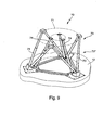
- eine perspektivische Darstellung eines elektromagnetisch angetriebenen Hexapoden;
- Fig. 10a
- eine schematische X-Z-Schnittansicht einer Fahrersitz-Aktorik;
- Fig. 10b
- eine schematische X-Y-Schnittansicht der Fahrersitz-Aktorik der Figur 10a.
- einen Drehteller 8, mittels dessen die Kabine 5 um ihre Vertikalachse 9 gedreht werden kann;
- eine sechsachsige Bewegungseinheit 10 zur Bewegung des Zusammenbaus aus Drehteller 8 und Kabine 5 in allen sechs Raumfreiheitsgraden (drei translatorische Freiheitsgrade und drei rotatorische Freiheitsgrade);
- eine Horizontalverschiebevorrichtung 11 zur gesteuerten Verschiebung und Beschleunigung des Zusammenbaus aus sechsachsiger Bewegungseinheit 10, Drehteller 8 und Kabine 5 entlang der beiden Horizontalachsen X und Y.
- Der Bewegungsraum der Portalbrücke 26 und somit der erforderliche Arbeitsraum der Antriebe 36,36' ergibt sich aus den Abmaßen der Bodenfläche 13 und ist daher sehr groß (er umfasst im hier betrachteten Ausführungsbeispiel - wie oben beschrieben - 54 m).
- Die maximal benötigte Antriebskraft für die Portalbrücke
26 in X-Richtung beträgt etwa 300 000 N. Dies ergibt sich
aus der für extreme Fahrmanöver geforderten Beschleunigung
von 0.6 g und der zulässigen bewegten Gesamtmasse des Zusammenbaus
aus Portalbrücke 26 und Basiseinheit 14 von bis
zu 50 t. Bei der Dimensionierung der beiden Einzelantriebe
36,36' ist dabei eine extreme Randposition der Basiseinheit
14 zu berücksichtigen. Diese führt zu Schwankungen im
Kraftbedarf der Einzelantriebe 36,36' von bis zu +-20%.
Jeder Einzelantrieb 36,36' muss somit eine maximale Kraft von 180.000 N aufbringen. - Aus Simulationsrechnungen mit entsprechenden Lastprofilen ergibt sich eine geforderte Antriebsleistung von 20 W/kg in X-Richtung.
- Die für eine realitätsnahe Simulation ausgewählter Fahrmanöver geforderte Beschleunigungsauflösung bzw. Beschleunigungsquantisierung liegt bei 0.02 m/s2. Daraus ergibt sich, dass die Antriebskraft der Portalbrücke 26 feiner als 1000 N dosierbar sein muss. Außerdem müssen konzeptbedingte Störkräfte (z.B. Reibung) kleiner als 5000 N sein, um sicherzustellen, dass Fehler in der Beschleunigungsdarstellung kleiner als 0.1 m/s2 sind.
Claims (19)
- Bewegungssystem für einen Fahrsimulator zur Erzeugung von Bewegungseindrücken auf Testpersonendadurch gekennzeichnet, dass die Kabine (5) ortsfest auf einem Manipulator (7) angeordnet ist, welcher die folgenden Komponenten umfasst:mit einer Kabine, die einen Sitz und Lenkeinrichtungen und Betätigungspedale umfasst,wobei der Sitz und/oder die Lenkeinrichtungen und Betätigungspedale jeweils über Aufnahmen beweglich angeordnet sind und über zugeordnete Stellelemente in mehreren Bewegungsrichtungen über eine Steuereinheit zur Verschiebung relativ zueinander veränderlich ansteuerbar sind,und dass die sechsachsige Bewegungseinheit (10) ortsfest auf einem Trägerschlitten (12) montiert ist, welcher frei verschieblich auf einer durch die Verfahrwege der Horizontalverschiebevorrichtung (11) aufgespannten ebenen Bodenfläche (13) gelagert ist und mittels der Horizontalverschiebevorrichtung (11) gegenüber dieser Bodenfläche (13) gezogen und/oder geschoben wird.einen Drehteller (8) zur gesteuerten Drehbewegung der Kabine (5) um ihre Vertikalachse,eine sechsachsige Bewegungseinheit (10) zur Bewegung des Zusammenbaus aus Drehteller (8) und Kabine (5) in allen sechs Raumfreiheitsgraden,eine Horizontalverschiebevorrichtung (11) zur gesteuerten Verschiebung und Beschleunigung des Zusammenbaus aus sechsachsiger Bewegungseinheit (10), Drehteller (8) und Kabine (5) entlang der beiden Horizontalachsen,
- Bewegungssystem nach Anspruch 1,
dadurch gekennzeichnet, dass der Trägerschlitten (12) über Luftlager (16) und/oder Luftkissen gegenüber der Bodenfläche (13) gelagert ist. - Bewegungssystem nach Anspruch 1 oder 2,
dadurch gekennzeichnet, dass die Horizontalverschiebevorrichtung (11) aus zwei Linearverschiebevorrichtungen (24,25) besteht, und zwar auseiner ersten Linearverschiebevorrichtung (24) zur gesteuerten Verschiebung und Beschleunigung des Zusammenbaus aus sechsachsiger Bewegungseinheit (10), Drehteller (8) und Kabine (5) entlang einer ersten Horizontalachse (Y) undeiner zweiten Linearverschiebevorrichtung (25) zur gesteuerten Verschiebung und Beschleunigung des Zusammenbaus aus erster Linearverschiebevorrichtung (24), sechsachsiger Bewegungseinheit (10), Drehteller (8) und Kabine (5) entlang einer zweiten Horizontalachse (X), welche näherungsweise senkrecht gegenüber der ersten Horizontalachse (Y) ausgerichtet ist. - Bewegungssystem nach Anspruch 3,
dadurch gekennzeichnet, dass die zweite Linearverschiebevorrichtung (25) als Portalbrücke (26) ausgestaltet ist. - Bewegungssystem nach Anspruch 4,
dadurch gekennzeichnet, dass sich die Portalbrücke (26) über Luftlager (34) und /oder Luftkissen gegenüber der Bodenfläche (13) abstützt. - Bewegungssystem nach Anspruch 3 oder 4,
dadurch gekennzeichnet, dass die Bewegungsanregung der Portalbrücke (26) mittels zweier endseitig angeordneter Bandzugantriebe (37) erfolgt. - Bewegungssystem nach Anspruch 3 oder 4,
dadurch gekennzeichnet, dass die Bewegungsanregung der Portalbrücke (26) mittels zweier endseitig angeordneter elektromagnetischer Linearantriebe (43, 43') erfolgt. - Bewegungssystem nach Anspruch 6 oder 7,
dadurch gekennzeichnet, dass die Portalbrücke (26) mit einem der beiden Antriebe (36) über ein Drehgelenk (48) verbunden ist und gegenüber dem anderen Antrieb (36') über ein eine begrenzt linear in Y-Richtung verschiebliche Drehverbindung (49) gelagert ist. - Bewegungssystem nach einem der Ansprüche 4 bis 8,
dadurch gekennzeichnet, dass zum Antrieb der ersten Linearverschiebevorrichtung (24) ein elektromagnetischer Linearantrieb (51) vorgesehen ist, mit Hilfe dessen der Zusammenbau aus sechsachsiger Bewegungseinheit (10), Drehteller (8) und Kabine (5) gegenüber der Portalbrücke (26) verschiebbar ist. - Bewegungssystem nach Anspruch 3,
dadurch gekennzeichnet, dass der Trägerschlitten (12) über Koppelelemente (55,55') gegenüber der ersten Linearverschiebevorrichtung (24) abgestützt ist. - Bewegungssystem nach Anspruch 3,
dadurch gekennzeichnet, dass die Anbindung der ersten Linearverschiebevorrichtung (24) an die zweite Linearverschiebevorrichtung (25) in einer Höhe (85) erfolgt, die der Höhe des Schwerpunkts der zweiten Linearverschiebevorrichtung (25) entspricht. - Bewegungssystem nach Anspruch 3,
dadurch gekennzeichnet, dass der mindestens eine Antrieb (51) der ersten Linearverschiebevorrichtung (24) und/oder der mindestens eine Antrieb 36,36') der zweiten Linearverschiebevorrichtung (25) mit einem passiven Bremssystem versehen ist. - Bewegungssystem nach Anspruch 3,
dadurch gekennzeichnet, dass die erste und/oder die zweite Linearverschiebevorrichtung (24,25) mit einem Endanschlag (84) zur Ableitung der im Bremsfall auftretenden Kräfte versehen ist. - Bewegungssystem nach Anspruch 1 oder 2,
dadurch gekennzeichnet, dass die Horizontalverschiebevorrichtung (11) durch zwei Bandzugantriebe oder zwei Paare von Bandzugantrieben 60,60') gebildet ist, deren Wirkungsrichtungen näherungsweise senkrecht aufeinander stehen. - Bewegungssystem nach Anspruch 1 oder 2,
dadurch gekennzeichnet, dass die Horizontalverschiebevorrichtung (11) durch einen elektromagnetischen Planarantrieb (65) gebildet ist. - Bewegungssystem nach Anspruch 15,
dadurch gekennzeichnet, dass der elektromagnetische Planarantrieb (65) mindestens zwei elektromagnetisch angetriebene, synchron zueinander bewegbare Verfahrschuhe (67) umfasst, an welche der Trägerschlitten (12) mechanisch angekoppelt ist. - Bewegungssystem nach einem der vorhergehenden Ansprüche,
dadurch gekennzeichnet, dass die Bewegung der sechsachsigen Bewegungseinheit (10,70) mit Hilfe elektrischer Antriebe (73) erfolgt. - Bewegungssystem nach einem der vorhergehenden Ansprüche,
dadurch gekennzeichnet, dass die sechsachsige Bewegungseinheit (10) ein Hexapod (70) ist. - Bewegungssystem nach einem der vorhergehenden Ansprüche,
dadurch gekennzeichnet, dass die Kabine (5) in einem fest mit dem Drehteller (8) verbundenen Dom (4) angeordnet ist.
Applications Claiming Priority (3)
| Application Number | Priority Date | Filing Date | Title |
|---|---|---|---|
| DE10150382A DE10150382B4 (de) | 2001-10-11 | 2001-10-11 | Fahrsimulator |
| DE10150382 | 2001-10-11 | ||
| PCT/EP2002/009301 WO2003034373A1 (de) | 2001-10-11 | 2002-08-21 | Fahrsimulator |
Publications (2)
| Publication Number | Publication Date |
|---|---|
| EP1435082A1 EP1435082A1 (de) | 2004-07-07 |
| EP1435082B1 true EP1435082B1 (de) | 2005-12-14 |
Family
ID=7702281
Family Applications (1)
| Application Number | Title | Priority Date | Filing Date |
|---|---|---|---|
| EP02767408A Expired - Lifetime EP1435082B1 (de) | 2001-10-11 | 2002-08-21 | Fahrsimulator |
Country Status (5)
| Country | Link |
|---|---|
| US (1) | US20050042578A1 (de) |
| EP (1) | EP1435082B1 (de) |
| JP (1) | JP3915122B2 (de) |
| DE (2) | DE10150382B4 (de) |
| WO (1) | WO2003034373A1 (de) |
Cited By (3)
| Publication number | Priority date | Publication date | Assignee | Title |
|---|---|---|---|---|
| DE102009029318A1 (de) | 2009-09-09 | 2011-03-17 | Ford Global Technologies, LLC, Dearborn | Verfahren und Vorrichtung zur Erprobung einer Fahrzeugkonstruktion |
| DE102016123629A1 (de) | 2016-12-07 | 2018-06-07 | Dr. Ing. H.C. F. Porsche Aktiengesellschaft | Regelsystem für einen Lenkungsprüfstand |
| CN108958280A (zh) * | 2018-09-06 | 2018-12-07 | 成都泛美视界科技有限公司 | 两自由度微动座椅运动控制方法 |
Families Citing this family (47)
| Publication number | Priority date | Publication date | Assignee | Title |
|---|---|---|---|---|
| US20040191730A1 (en) * | 2001-12-17 | 2004-09-30 | Pierre Couder | Computer-assisted learning method and system for real time reproduction of a vehicle reactions |
| DE10308059B3 (de) * | 2003-02-26 | 2004-04-29 | Daimlerchrysler Ag | Linearverschiebesystem für einen Fahrsimulator |
| DE102004008625A1 (de) * | 2004-02-21 | 2005-09-08 | Daimlerchrysler Ag | Prüfvorrichtung zum Kippen und Schwenken eines Körpers |
| DE102005006069A1 (de) * | 2005-02-10 | 2006-08-24 | Hubert Kammer | Verfahren und Vorrichtung zum dreidimensionalen Scannen von Objekten |
| DE102005022096A1 (de) | 2005-05-12 | 2006-11-16 | Fraunhofer-Gesellschaft zur Förderung der angewandten Forschung e.V. | Vorrichtung und Verfahren zur vibroakustischen Untersuchung eines Kraftfahrzeuges |
| JP2007033562A (ja) * | 2005-07-22 | 2007-02-08 | Toyota Motor Corp | 運転模擬試験装置 |
| JP4736592B2 (ja) * | 2005-07-22 | 2011-07-27 | トヨタ自動車株式会社 | 運転模擬試験装置 |
| JP2008052216A (ja) * | 2006-08-28 | 2008-03-06 | Toyota Motor Corp | 運転模擬試験装置 |
| ATE530305T1 (de) * | 2006-12-19 | 2011-11-15 | Univ Deakin | Verfahren und vorrichtung zur haptischen steuerung |
| JP5014898B2 (ja) * | 2007-06-29 | 2012-08-29 | Thk株式会社 | ドライブシミュレータ用ステアリング及びドライブシミュレータ |
| US20090136903A1 (en) * | 2007-11-26 | 2009-05-28 | Mcneil Christopher Paul | Portable atv/ dirt bike/ snowmobile safety trainer and method for use |
| DE102009002169B4 (de) * | 2009-04-03 | 2022-04-21 | Zf Friedrichshafen Ag | Reifenprüfstand |
| JP5377171B2 (ja) * | 2009-09-04 | 2013-12-25 | 三菱プレシジョン株式会社 | 自動車シミュレータ |
| GB2474279B (en) * | 2009-10-09 | 2011-12-21 | Ansible Motion Ltd | Mobile platform |
| DE102009058491B4 (de) * | 2009-12-16 | 2017-07-06 | Audi Ag | Verfahren zur Präsentation wenigstens einer Funktionalität wenigstens eines Fahrerassistenzsystems für ein Kraftfahrzeug gegenüber einem Kunden und zugehörige Einspeisevorrichtung |
| FR2959942B1 (fr) | 2010-05-12 | 2013-06-14 | Guillemot Corp | Controleur de jeu a colonne de direction |
| DE102010035814B3 (de) * | 2010-08-30 | 2011-12-29 | Grenzebach Maschinenbau Gmbh | Vorrichtung und Verfahren zum Betrieb eines Flugsimulators mit besonderer Realitäts-Anmutung |
| RU2475186C2 (ru) * | 2011-02-10 | 2013-02-20 | Фирдаус Хасанович Ермаков | Устройство для измерения в стационарных условиях времени зрительно-моторной реакции водителя транспортного средства на опасные дорожные ситуации |
| ITUD20120011A1 (it) * | 2012-01-30 | 2013-07-31 | Diego Minen | Apparato per la simulazione della conduzione di un veicolo terrestre |
| US8930227B2 (en) * | 2012-03-06 | 2015-01-06 | State Farm Mutual Automobile Insurance Company | Online system for training novice drivers and rating insurance products |
| KR101198255B1 (ko) * | 2012-04-12 | 2012-11-07 | 주식회사 모션디바이스 | 모션 시뮬레이터 |
| NL2009805C2 (en) * | 2012-11-14 | 2014-05-15 | E2M Technologies B V | A 6 degree-of-freedom motion simulator assembly. |
| US9666094B2 (en) | 2012-12-04 | 2017-05-30 | Kabushiki Kaisha Saginomiya Seisakusho | Test device |
| JP5916893B2 (ja) * | 2012-12-04 | 2016-05-11 | 株式会社鷺宮製作所 | 試験装置 |
| JP5813706B2 (ja) | 2013-08-08 | 2015-11-17 | 株式会社鷺宮製作所 | 加振装置、および、それを備えるシミュレーター用加振システム |
| JP6425095B2 (ja) * | 2014-12-26 | 2018-11-21 | 株式会社ジェイテクト | 車両挙動再現システム |
| CN104623912B (zh) * | 2015-02-03 | 2017-01-04 | 深圳华侨城文化旅游科技股份有限公司 | 一种循环式动感车观影系统 |
| JP6425090B2 (ja) * | 2015-02-13 | 2018-11-21 | 株式会社ジェイテクト | 車両挙動再現システム |
| JP6425091B2 (ja) * | 2015-02-13 | 2018-11-21 | 株式会社ジェイテクト | 車両挙動再現システム |
| JP6489355B2 (ja) * | 2015-02-24 | 2019-03-27 | 株式会社ジェイテクト | 車両挙動再現システム |
| WO2016149649A1 (en) * | 2015-03-18 | 2016-09-22 | Michigan Scientific Corporation | Transducer calibration apparatus |
| ITUB20152709A1 (it) * | 2015-07-31 | 2017-01-31 | Vi Grade Ag | Apparato per la simulazione della conduzione di un veicolo terrestre |
| GB201515730D0 (en) | 2015-09-04 | 2015-10-21 | Mclaren Racing Ltd | Motion platform |
| FR3067155B1 (fr) * | 2017-06-01 | 2022-01-28 | Thales Sa | Dispositif de securisation des mouvements electriques de plateformes mobiles pour simulateurs |
| EP3489932A1 (de) | 2017-11-23 | 2019-05-29 | E2M Technologies B.V. | Bewegungsplattformsystem |
| EP3493181B1 (de) * | 2017-11-30 | 2020-04-15 | Robert Bosch GmbH | Simulationseinheit zur simulation einer fahrzeugbewegung |
| IT201800005022A1 (it) * | 2018-05-03 | 2019-11-03 | Apparato per la simulazione della conduzione di un veicolo terrestre | |
| CN108877379A (zh) * | 2018-09-10 | 2018-11-23 | 苏州大成有方数据科技有限公司 | 一种活动式工程模拟器的自动控制系统 |
| CN109147454A (zh) * | 2018-09-10 | 2019-01-04 | 苏州大成有方数据科技有限公司 | 一种工程模拟器的自动控制系统 |
| IT201800003923U1 (it) * | 2018-12-12 | 2020-06-12 | Cresno Sa | Dispositivo ottimizzato per la simulazione di esperienze motorie |
| ES3049635T3 (en) * | 2019-04-26 | 2025-12-17 | Dynisma Ltd | Motion system |
| GB201908351D0 (en) * | 2019-06-11 | 2019-07-24 | Dynismo Ltd | Motion system |
| DE102019116663A1 (de) * | 2019-06-19 | 2020-12-24 | 4Activesystems Gmbh | Neigungsmechanik für einspurige Dummy Fahrzeuge |
| NL2023724B1 (en) | 2019-08-29 | 2021-05-11 | E2M Tech B V | Driving simulator |
| JP7297151B2 (ja) * | 2020-07-03 | 2023-06-23 | 深▲せん▼怡豊自動化科技有限公司 | Agv娯楽運輸工具及び接続組立体 |
| CN113628497A (zh) * | 2021-09-16 | 2021-11-09 | 河南科技大学 | 一种能够实现高低频复合振动的车辆驾驶模拟器 |
| DE102022112464B3 (de) | 2022-05-18 | 2023-09-28 | Deutsches Zentrum für Luft- und Raumfahrt e.V. | Roboter mit daran gekoppelter Gondel |
Family Cites Families (23)
| Publication number | Priority date | Publication date | Assignee | Title |
|---|---|---|---|---|
| US3135057A (en) * | 1960-04-28 | 1964-06-02 | Northrop Corp | Flight simulator |
| CH438627A (de) * | 1964-03-03 | 1967-06-30 | Poroli Vincenzo | Bockkran mit aus Mastschüssen aufstockbaren Stützmasten |
| US3602375A (en) * | 1969-02-10 | 1971-08-31 | Koehring Co | Piggyback load handling crane |
| US3577655A (en) * | 1969-05-19 | 1971-05-04 | Singer General Precision | Motion simulator |
| US3784028A (en) * | 1972-06-09 | 1974-01-08 | Dresser Ind | Gantry crane |
| US4106641A (en) * | 1976-03-17 | 1978-08-15 | Algoship International Limited | Universal gantry crane |
| DE2842409A1 (de) * | 1978-09-29 | 1980-04-17 | Daimler Benz Ag | Verfahren und einrichtung zur vermittlung des eindrucks einer horizontalbeschleunigung bei fahrsimulation |
| US4467250A (en) * | 1982-12-10 | 1984-08-21 | Newport Corporation | Electric motor controls for mechanical actuators |
| US4581553A (en) * | 1984-04-16 | 1986-04-08 | Helmut Moczala | Brushless DC motor, especially linear motor, having an increased force-to-velocity ratio |
| GB2179605B (en) * | 1985-08-27 | 1988-11-16 | Singer Link Miles Ltd | Motion simulator |
| US4860600A (en) * | 1987-04-20 | 1989-08-29 | Schumacher Larry L | Three degree of freedom micro-gravity simulator |
| GB8807221D0 (en) * | 1988-03-25 | 1988-04-27 | Super X Ltd | Motion simulator mechanism |
| DE3936877A1 (de) * | 1989-11-06 | 1991-05-08 | Mak Maschinenbau Krupp | Fahrsimulator |
| FR2677155B1 (fr) * | 1991-05-31 | 1994-08-26 | Thomson Csf | Simulateur de voiture automobile. |
| GB2279316B (en) * | 1993-06-08 | 1997-03-26 | Compacific Engineering Pte Lim | Multi-tier jack motion system |
| US5385249A (en) * | 1993-07-27 | 1995-01-31 | Harnischfeger Corporation | Material handling machine with force-isolating support link |
| US5492067A (en) * | 1994-08-08 | 1996-02-20 | Harnischfeger Corporation | System and method for maintaining plural driven components at reference positions |
| US5919045A (en) * | 1996-11-18 | 1999-07-06 | Mariah Vision3 Entertainment Llc | Interactive race car simulator system |
| FR2757440B1 (fr) * | 1996-12-20 | 1999-03-19 | Conservatoire Nat Arts | Plateforme hexapode et dispositifs d'articulation spherique utilisables pour sa realisation |
| JP2945884B2 (ja) * | 1997-06-13 | 1999-09-06 | コナミ株式会社 | 体感ドライブ装置 |
| GB9912611D0 (en) * | 1999-05-28 | 1999-07-28 | Rolt Richard C | A printing machine |
| KR100354343B1 (ko) * | 1999-06-11 | 2002-09-28 | 김의석 | 운동모사장치 |
| JP2002014604A (ja) * | 2000-06-30 | 2002-01-18 | Central Japan Railway Co | 鉄道の乗心地模擬装置 |
-
2001
- 2001-10-11 DE DE10150382A patent/DE10150382B4/de not_active Expired - Fee Related
-
2002
- 2002-08-21 EP EP02767408A patent/EP1435082B1/de not_active Expired - Lifetime
- 2002-08-21 DE DE50205301T patent/DE50205301D1/de not_active Expired - Lifetime
- 2002-08-21 US US10/492,185 patent/US20050042578A1/en not_active Abandoned
- 2002-08-21 JP JP2003537026A patent/JP3915122B2/ja not_active Expired - Fee Related
- 2002-08-21 WO PCT/EP2002/009301 patent/WO2003034373A1/de not_active Ceased
Cited By (5)
| Publication number | Priority date | Publication date | Assignee | Title |
|---|---|---|---|---|
| DE102009029318A1 (de) | 2009-09-09 | 2011-03-17 | Ford Global Technologies, LLC, Dearborn | Verfahren und Vorrichtung zur Erprobung einer Fahrzeugkonstruktion |
| CN102024073A (zh) * | 2009-09-09 | 2011-04-20 | 福特全球技术公司 | 测试车辆设计的方法和装置 |
| DE102016123629A1 (de) | 2016-12-07 | 2018-06-07 | Dr. Ing. H.C. F. Porsche Aktiengesellschaft | Regelsystem für einen Lenkungsprüfstand |
| CN108958280A (zh) * | 2018-09-06 | 2018-12-07 | 成都泛美视界科技有限公司 | 两自由度微动座椅运动控制方法 |
| CN108958280B (zh) * | 2018-09-06 | 2021-07-27 | 成都泛美视界科技有限公司 | 两自由度微动座椅运动控制方法 |
Also Published As
| Publication number | Publication date |
|---|---|
| DE10150382A1 (de) | 2003-04-30 |
| EP1435082A1 (de) | 2004-07-07 |
| US20050042578A1 (en) | 2005-02-24 |
| WO2003034373A1 (de) | 2003-04-24 |
| JP2005505783A (ja) | 2005-02-24 |
| JP3915122B2 (ja) | 2007-05-16 |
| DE50205301D1 (de) | 2006-01-19 |
| DE10150382B4 (de) | 2006-03-23 |
Similar Documents
| Publication | Publication Date | Title |
|---|---|---|
| EP1435082B1 (de) | Fahrsimulator | |
| DE69512491T2 (de) | Aktives Führungssystem eines Aufzuges | |
| DE69127786T2 (de) | Aktives Aufzugsaufhängesystem | |
| EP0366883B1 (de) | Verfahren und Vorrichtung zur Ausübung des Verfahrens für die Schwingungsabsorbierung an Kabinen bei schnellaufenden Aufzügen | |
| DE3931753C2 (de) | ||
| DE102011085791B4 (de) | Prüfeinrichtung für Crash-Simulationsversuche | |
| EP3904249B1 (de) | Planarmotor mit einer führungsvorrichtung für shuttles des planarmotors | |
| DE60112937T2 (de) | Werkzeugmaschine und manipulatoranordnung, die auf einer solchen maschine montiert ist | |
| DE112009000488B4 (de) | Testsystem mit Strebenanordnung sowie Verfahren | |
| DE102004030659B4 (de) | Bewegungsvorrichtung | |
| EP2098850B1 (de) | Anordnung zur Simulation von Aufprallunfällen | |
| DE10212255B4 (de) | Straßensimulationsprüfstand | |
| DE102012101979B4 (de) | Verfahren und Vorrichtung zur Erzeugung einer Relativbewegung | |
| DE4223307A1 (de) | Aeromagnetische steuerung von magnetschwebefahrzeugen | |
| DE102006056335A1 (de) | Magnetschwebefahrzeug mit wenigstens einem Magnetsystem | |
| DE10308059B3 (de) | Linearverschiebesystem für einen Fahrsimulator | |
| DE102012023076B4 (de) | Vorrichtung zur Simulation von Unfallszenarien | |
| DE3941685A1 (de) | Einrichtung zur fesselung von testobjekten in einem vorgegebenen fesselpunkt | |
| WO2010022892A2 (de) | Manipulator | |
| DE69505748T2 (de) | Bewegliche Plattform und ihre Anwendung zur Verwirklichung einer Simulations-Kabine | |
| WO2017149066A1 (de) | Linearmotoranordnung für eine aufzugsanlage | |
| DE202023002212U1 (de) | Hochdynamischer Pulsator zur Federwegsimulation bei Gelenkwellenprüfständen | |
| DE102004045125A1 (de) | Fahrsimulator | |
| EP2361049A1 (de) | Magnetspulenanordnung mit festen und beweglichen spulen | |
| DE10217720C1 (de) | Vorrichtung zum Testen einer Radaufhängung an einem Fahrzeug |
Legal Events
| Date | Code | Title | Description |
|---|---|---|---|
| PUAI | Public reference made under article 153(3) epc to a published international application that has entered the european phase |
Free format text: ORIGINAL CODE: 0009012 |
|
| 17P | Request for examination filed |
Effective date: 20040315 |
|
| AK | Designated contracting states |
Kind code of ref document: A1 Designated state(s): AT BE BG CH CY CZ DE DK EE ES FI FR GB GR IE IT LI LU MC NL PT SE SK TR |
|
| RIN1 | Information on inventor provided before grant (corrected) |
Inventor name: FAUL, RUEDIGER Inventor name: DUPLITZER, ENNO Inventor name: BOETTIGER, FRIEDRICH Inventor name: PETERSEN, UWE Inventor name: HOFFMEYER, FRIEDRICH Inventor name: AMMON, DIETER Inventor name: LAESSING, MARC Inventor name: SCHULZ, THOMAS Inventor name: HERMLE, MARKUS Inventor name: GOETZ, JOCHEN Inventor name: RUSSOW, JOERG |
|
| 17Q | First examination report despatched |
Effective date: 20041012 |
|
| GRAP | Despatch of communication of intention to grant a patent |
Free format text: ORIGINAL CODE: EPIDOSNIGR1 |
|
| GRAS | Grant fee paid |
Free format text: ORIGINAL CODE: EPIDOSNIGR3 |
|
| GRAA | (expected) grant |
Free format text: ORIGINAL CODE: 0009210 |
|
| AK | Designated contracting states |
Kind code of ref document: B1 Designated state(s): DE FR GB |
|
| PG25 | Lapsed in a contracting state [announced via postgrant information from national office to epo] |
Ref country code: GB Free format text: LAPSE BECAUSE OF FAILURE TO SUBMIT A TRANSLATION OF THE DESCRIPTION OR TO PAY THE FEE WITHIN THE PRESCRIBED TIME-LIMIT Effective date: 20051214 |
|
| REG | Reference to a national code |
Ref country code: GB Ref legal event code: FG4D Free format text: NOT ENGLISH |
|
| REF | Corresponds to: |
Ref document number: 50205301 Country of ref document: DE Date of ref document: 20060119 Kind code of ref document: P |
|
| GBV | Gb: ep patent (uk) treated as always having been void in accordance with gb section 77(7)/1977 [no translation filed] |
Effective date: 20051214 |
|
| PLBE | No opposition filed within time limit |
Free format text: ORIGINAL CODE: 0009261 |
|
| STAA | Information on the status of an ep patent application or granted ep patent |
Free format text: STATUS: NO OPPOSITION FILED WITHIN TIME LIMIT |
|
| 26N | No opposition filed |
Effective date: 20060915 |
|
| EN | Fr: translation not filed | ||
| PG25 | Lapsed in a contracting state [announced via postgrant information from national office to epo] |
Ref country code: FR Free format text: LAPSE BECAUSE OF FAILURE TO SUBMIT A TRANSLATION OF THE DESCRIPTION OR TO PAY THE FEE WITHIN THE PRESCRIBED TIME-LIMIT Effective date: 20070202 |
|
| PG25 | Lapsed in a contracting state [announced via postgrant information from national office to epo] |
Ref country code: FR Free format text: LAPSE BECAUSE OF FAILURE TO SUBMIT A TRANSLATION OF THE DESCRIPTION OR TO PAY THE FEE WITHIN THE PRESCRIBED TIME-LIMIT Effective date: 20051214 |
|
| PGFP | Annual fee paid to national office [announced via postgrant information from national office to epo] |
Ref country code: DE Payment date: 20141031 Year of fee payment: 13 |
|
| REG | Reference to a national code |
Ref country code: DE Ref legal event code: R119 Ref document number: 50205301 Country of ref document: DE |
|
| PG25 | Lapsed in a contracting state [announced via postgrant information from national office to epo] |
Ref country code: DE Free format text: LAPSE BECAUSE OF NON-PAYMENT OF DUE FEES Effective date: 20160301 |