EP1435218A1 - Verfahren und Vorrichtung zur Lokalisierung visceraler Verengungen - Google Patents
Verfahren und Vorrichtung zur Lokalisierung visceraler Verengungen Download PDFInfo
- Publication number
- EP1435218A1 EP1435218A1 EP02447243A EP02447243A EP1435218A1 EP 1435218 A1 EP1435218 A1 EP 1435218A1 EP 02447243 A EP02447243 A EP 02447243A EP 02447243 A EP02447243 A EP 02447243A EP 1435218 A1 EP1435218 A1 EP 1435218A1
- Authority
- EP
- European Patent Office
- Prior art keywords
- balloon
- catheter
- electrodes
- compressible
- read
- Prior art date
- Legal status (The legal status is an assumption and is not a legal conclusion. Google has not performed a legal analysis and makes no representation as to the accuracy of the status listed.)
- Withdrawn
Links
- 238000000034 method Methods 0.000 title claims abstract description 29
- 230000009278 visceral effect Effects 0.000 title claims abstract description 14
- 230000006835 compression Effects 0.000 claims abstract description 19
- 238000007906 compression Methods 0.000 claims abstract description 19
- 230000001419 dependent effect Effects 0.000 claims abstract description 9
- 241001465754 Metazoa Species 0.000 claims abstract description 6
- 239000007788 liquid Substances 0.000 claims description 35
- 238000005259 measurement Methods 0.000 claims description 29
- 239000006260 foam Substances 0.000 claims description 23
- 239000000463 material Substances 0.000 claims description 16
- 239000004020 conductor Substances 0.000 claims description 15
- 239000012528 membrane Substances 0.000 claims description 8
- 230000000903 blocking effect Effects 0.000 claims description 6
- 239000002775 capsule Substances 0.000 claims description 5
- 239000008187 granular material Substances 0.000 claims description 5
- 238000012544 monitoring process Methods 0.000 claims description 2
- 210000000111 lower esophageal sphincter Anatomy 0.000 description 29
- 210000000056 organ Anatomy 0.000 description 21
- 208000021302 gastroesophageal reflux disease Diseases 0.000 description 9
- 230000007423 decrease Effects 0.000 description 5
- 210000004283 incisor Anatomy 0.000 description 5
- 238000002474 experimental method Methods 0.000 description 4
- 241000282326 Felis catus Species 0.000 description 3
- 210000000941 bile Anatomy 0.000 description 3
- 238000001839 endoscopy Methods 0.000 description 3
- 210000003238 esophagus Anatomy 0.000 description 3
- 239000012530 fluid Substances 0.000 description 3
- 238000003780 insertion Methods 0.000 description 3
- 230000037431 insertion Effects 0.000 description 3
- 230000033001 locomotion Effects 0.000 description 3
- 210000002784 stomach Anatomy 0.000 description 3
- 210000004204 blood vessel Anatomy 0.000 description 2
- 230000003247 decreasing effect Effects 0.000 description 2
- 230000003176 fibrotic effect Effects 0.000 description 2
- 230000005176 gastrointestinal motility Effects 0.000 description 2
- 210000001035 gastrointestinal tract Anatomy 0.000 description 2
- 230000004807 localization Effects 0.000 description 2
- 230000003287 optical effect Effects 0.000 description 2
- 208000031481 Pathologic Constriction Diseases 0.000 description 1
- 208000037273 Pathologic Processes Diseases 0.000 description 1
- 230000002159 abnormal effect Effects 0.000 description 1
- 239000002253 acid Substances 0.000 description 1
- 230000008602 contraction Effects 0.000 description 1
- 238000011847 diagnostic investigation Methods 0.000 description 1
- 208000010643 digestive system disease Diseases 0.000 description 1
- 230000010339 dilation Effects 0.000 description 1
- 230000002497 edematous effect Effects 0.000 description 1
- 238000011156 evaluation Methods 0.000 description 1
- 210000004211 gastric acid Anatomy 0.000 description 1
- 230000002496 gastric effect Effects 0.000 description 1
- 239000011796 hollow space material Substances 0.000 description 1
- 238000003384 imaging method Methods 0.000 description 1
- 238000002847 impedance measurement Methods 0.000 description 1
- 230000002757 inflammatory effect Effects 0.000 description 1
- 238000012332 laboratory investigation Methods 0.000 description 1
- 230000003902 lesion Effects 0.000 description 1
- 230000004899 motility Effects 0.000 description 1
- 210000003205 muscle Anatomy 0.000 description 1
- 238000001139 pH measurement Methods 0.000 description 1
- 230000001575 pathological effect Effects 0.000 description 1
- 230000009054 pathological process Effects 0.000 description 1
- 230000035479 physiological effects, processes and functions Effects 0.000 description 1
- 230000007505 plaque formation Effects 0.000 description 1
- 229920001296 polysiloxane Polymers 0.000 description 1
- 229920002635 polyurethane Polymers 0.000 description 1
- 239000004814 polyurethane Substances 0.000 description 1
- 230000002265 prevention Effects 0.000 description 1
- 230000000135 prohibitive effect Effects 0.000 description 1
- 210000004203 pyloric antrum Anatomy 0.000 description 1
- 238000011002 quantification Methods 0.000 description 1
- 238000011158 quantitative evaluation Methods 0.000 description 1
- 230000005855 radiation Effects 0.000 description 1
- 238000010992 reflux Methods 0.000 description 1
- 239000000523 sample Substances 0.000 description 1
- 239000007787 solid Substances 0.000 description 1
- 210000005070 sphincter Anatomy 0.000 description 1
- 208000024891 symptom Diseases 0.000 description 1
- 238000002560 therapeutic procedure Methods 0.000 description 1
- 210000001519 tissue Anatomy 0.000 description 1
- 230000004614 tumor growth Effects 0.000 description 1
- 230000001173 tumoral effect Effects 0.000 description 1
- 238000012795 verification Methods 0.000 description 1
- 210000001835 viscera Anatomy 0.000 description 1
- 238000012800 visualization Methods 0.000 description 1
Images

Classifications
-
- A—HUMAN NECESSITIES
- A61—MEDICAL OR VETERINARY SCIENCE; HYGIENE
- A61B—DIAGNOSIS; SURGERY; IDENTIFICATION
- A61B5/00—Measuring for diagnostic purposes; Identification of persons
- A61B5/42—Detecting, measuring or recording for evaluating the gastrointestinal, the endocrine or the exocrine systems
-
- A—HUMAN NECESSITIES
- A61—MEDICAL OR VETERINARY SCIENCE; HYGIENE
- A61B—DIAGNOSIS; SURGERY; IDENTIFICATION
- A61B5/00—Measuring for diagnostic purposes; Identification of persons
- A61B5/103—Measuring devices for testing the shape, pattern, colour, size or movement of the body or parts thereof, for diagnostic purposes
- A61B5/107—Measuring physical dimensions, e.g. size of the entire body or parts thereof
- A61B5/1076—Measuring physical dimensions, e.g. size of the entire body or parts thereof for measuring dimensions inside body cavities, e.g. using catheters
-
- A—HUMAN NECESSITIES
- A61—MEDICAL OR VETERINARY SCIENCE; HYGIENE
- A61B—DIAGNOSIS; SURGERY; IDENTIFICATION
- A61B5/00—Measuring for diagnostic purposes; Identification of persons
- A61B5/42—Detecting, measuring or recording for evaluating the gastrointestinal, the endocrine or the exocrine systems
- A61B5/4211—Diagnosing or evaluating reflux
Definitions
- the present invention is related to the determination of the location of an anatomical or functional constriction of a hollow body organ, such as the lower esophageal sphincter (LES) in the gastroesophageal junctional segment, or constrictions in other tubular organs of the body such as other parts of the gastrointestinal tract, the pancreatico-biliary tract, the genito-urinary tract, and blood vessels.
- a hollow body organ such as the lower esophageal sphincter (LES) in the gastroesophageal junctional segment
- constrictions in other tubular organs of the body such as other parts of the gastrointestinal tract, the pancreatico-biliary tract, the genito-urinary tract, and blood vessels.
- the lower esophageal sphincter has a crucial role in the prevention of gastroesophageal reflux (GER) and of the pathological effects thereof.
- gastroesophageal reflux refers to the backflow of gastric contents, particularly of gastric acid and bile, from the stomach, into the esophagus. When this reflux occurs too often or lasts too long, it results in symptoms and lesions of gastroesophageal reflux disease (GERD).
- the quantitative evaluation of gastroesophageal reflux is based on measurement of intraesophageal acidity and bile concentration, using devices (such as pH electrodes, acid exposure sensors, and bile sensors) that have to be positioned at a defined distance above the upper border of the LES. Therefore, the first step in the quantification of abnormal gastroesophageal reflux is the determination of the location of the upper border of the lower esophageal sphincter.
- Determining the location of a constriction in a hollow organ is a problem which is applicable to other organs as well.
- 'constriction' means a localised decrease of the lumen of a hollow organ or a localised decrease of distensibility of such an organ.
- a constriction may be anatomical or functional.
- An anatomical constriction is caused by a fibrotic, edematous, inflammatory, tumoral or plaque-forming process in the wall of the hollow organ or it may be due to normal structures or pathological processes in the tissues surrounding the said organ.
- a functional constriction is due to the contractile state of the muscles of the hollow organ, such as that which occurs in sphincteric segments.
- LES lower esophageal sphincter
- the radiological identification of the LES requires a fluoroscopic examination by a specialised radiologist and imposes ionising radiation upon the patient.
- the visualisation and location of the LES on radiological images does not allow to position an exploring device at a defined level above the sphincter, unless the device is introduced and positioned in the esophagus during the radiological examination.
- Endoscopy frequently does not allow to determine the upper limit of the lower esophageal sphincter. Moreover, endoscopy is an invasive and specialised examination.
- the wall motion device was developed to detect those gastric antrum contractions that substantially narrow the lumen of the antrum without resulting in an occlusion of that lumen.
- the device is described in 'Evaluation of patterns of human antral and pyloric motility with an antral wall motor detector', American Journal of Physiology, 1990;258;G616-G623.
- the most important drawbacks of the wall motion device for determining constrictions in a hollow organ are : firstly, that it measures the diameter changes in a given plane of hollow organ, not the volume changes, and, therefore, will fail to detect a flattening of the lumen which leaves the diameter of that lumen unchanged in the plane of the detector; secondly that its dimensions are such that they make the introduction through the nose very difficult and often impossible, and thirdly that the technique is too complicated to be used for clinical purposes.
- the aim of the present invention is to obtain a method and device which may determine the location of a visceral constriction in a hollow organ in a simple and inexpensive way, so that it may be used in a medical office outside a hospital environment, without the help of radiological, endoscopic or manometric techniques.
- the present invention is related to a device for determining the location of a visceral constriction in a human or animal body, said device comprising :
- said compressible element is a balloon filled with a liquid or a gas.
- a device of the invention may comprise :
- Said container may be a vessel equipped with a piston or said container may be a balloon.
- said element of variable volume comprises a compressible material, which is electrically conductive, and whereof the electrical resistance is dependent on the compression of said material.
- a device of the invention may comprise :
- said element may consist of a piece of electrically conductive foam, enveloped by a membrane, or it may consist of a capsule containing electrically conductive granules.
- said element of variable volume consists of a closed balloon consisting of a first and second chamber, connected to each other by a tube, a liquid being present in said balloon, one of said chambers comprising a transducer, which is able to detect said liquid being pressed from the other chamber into said one chamber.
- the device of the invention may comprise :
- said element of variable volume comprises a balloon at one end, and a rigid hollow body at the other, said balloon and said rigid body being connected by a tube, and a gas being present inside the space formed by said element, said rigid hollow body further comprising a compressible body, which is separated from said gas by a membrane in such a way that said compressible body can be compressed by gas which is pressed out of said balloon and into said rigid hollow body, and wherein said compressible body comprises a compressible material, which is electrically conductive, and whereof the electrical resistance is dependent on the compression of said material.
- said material may be an electrically conductive foam, or said material may consist of electrically conductive granules.
- the device of the invention may comprise :
- the present invention is equally related to a method for determining the location of a visceral constriction, said method comprising the steps of :
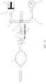
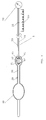
- Figures 1a and 1b are schematic representations of a balloon-catheter based device according to the present invention.
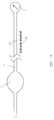
- Figure 2 is a schematic representation of a device according to the invention, based on a detector made of compressible foam.
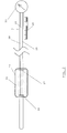
- Figure 3 is a schematic representation of a device according to the invention, based on a detector made of a closed liquid-filled balloon.
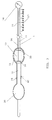
- Figure 4 and 5 are schematic representations of a device according to the invention, based on a gas-filled detector.
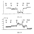
- Figure 6 shows results of an experiment, comparing a device of the invention to a prior art manometric device.
- the present invention is related to a device which comprises an element which has a variable volume, a means to pick up the volume changes the element undergoes when it is pulled through a constriction in the body organ, and a measuring/displaying/recording system, to show the volume changes which occur at each of the measuring levels during the pull-through procedure.
- a device of the invention further comprises a means for measuring the distance over which the element has been pulled.
- the volume change detector may be a fluid- or gas filled balloon, a spongelike compressible body or another structure which is able to undergo volume changes when it is pulled through a constriction in a hollow organ of the body and to re-assume its original volume when it is out of that constriction.
- the measuring system may be contained within the volume detector from where it is connected to an external (out of the body) displaying system.
- the measuring system may also be separate from the volume change detector but connected to it, inside or outside the body.
- the measuring system is also connected to the displaying system which shows the volume changes measured at various levels of the constriction during the pull-through procedure, thus allowing to localize the constriction in the hollow organ as the distance (e.g. in centimetres) from the port of entry into the body onto the margins of the constriction.
- Figure 1a shows a device according to a first embodiment of the invention.
- the device comprises a catheter 1, connected to a balloon 2, the interior of which is in connection with the interior of the catheter, i.e. the balloon and catheter enclose a continuous hollow space.
- the catheter is equipped with a three-way stopcock 3, which is connected by a first connecting tube 4 to a container 5 with variable content, and by a second connecting tube 6 to a measurement and read-out device 7.
- a liquid is present in the device as shown in figure 1a.
- the container 5 may be a vessel equipped with a piston 8, which is the case in the figure 1a.
- the measurement and read-out device 7 may for example comprise a vertical liquid column, connected to the catheter and balloon, so that a volume change of the balloon may be translated into a change in liquid column height.
- the stopcock 3 can be put in a first position, connecting the interior of the catheter 1 and balloon 2 with the interior of the container 5, while blocking the connection of the catheter 1 to the measurement and read-out device 7. In that way, the liquid may be induced to flow from the container to the balloon and vice versa.
- the stopcock 3 By moving the stopcock 3 to a second position, the interior of the catheter 1 and balloon 2 can be put in connection with the measurement and read-out device 7, while blocking the connection between the balloon 2 and the container 5.
- the device operates in a straightforward way. Before insertion of the device, the liquid contained in the balloon 2 is induced to flow into the container 5, by the piston movement or by compression of balloon 2, thereby emptying the balloon 2. Deflating the balloon in this way facilitates insertion of the catheter and balloon into the body.
- the catheter would be inserted through the nose of a patient, sufficiently far for the balloon to enter the stomach.
- the balloon is filled with liquid from the container 5 through the piston action, with the stopcock 3 in the first position.
- the stopcock 3 is moved to the second position, connecting the filled balloon with the measurement and read-out device 7. After that, the catheter and balloon are pulled out slowly.
- the device is equipped with a means for measuring the distance the balloon has been pulled out.
- This may be a simple ruler 10, along which the catheter is moved during the pull-through action, in combination with a marking 11 on the catheter, so that the distance over which the catheter has been pulled out can be recorded with respect to a reference position, for example the position wherein the marking 11 coincides with the beginning of the ruler 10.
- a reference position for example the position wherein the marking 11 coincides with the beginning of the ruler 10.
- other and more sophisticated means for measuring the pull-out distance may be implemented as well, but it is imperative that this distance can be monitored.
- the balloon enters the LES at some point.
- the diameter of the liquid-filled balloon is larger than the diameter of the LES, so that the balloon is compressed when it is pulled through the closed LES, leading to a change in its volume. Liquid is pressed out of the balloon as a consequence, and flows towards the read-out device 7.
- Compression of the balloon is thereby detected, for example through a rise in height of a liquid column, at which point it is established that the balloon has entered the LES.
- the balloon undergoes further compression, as it passes the LES. Leaving the LES, the balloon reassumes its former volume, which is detected as a decrease in liquid column height.
- the device of the invention allows thus to detect the position of the LES, by recording the volume changes indicated on the read-out device, as a function of the pull-through distance. More specifically, the device allows to locate the upper border of the LES as a sharp decrease in the height of a liquid column, caused by the sudden return of the volume detector, i.e. the balloon, to the volume it had before entering the constriction formed by the LES.
- the device may be used to detect any other visceral constriction.
- the dimensions of the device (length and diameter of catheter, dimensions of the balloon, etc..) will have to be adapted to every specific case.
- the balloon is made of a thin membrane. This balloon has a length of a few millimetres to a few centimetres, depending upon the nature and location of the constriction. The maximum diameter of the balloon is usually from three to ten millimetres.
- the container 5 can be a second balloon. It is imperative that the container's volume can be increased or decreased as required by the procedure which has to be performed. In other words, it has to be able to accommodate the liquid pressed out of the balloon which is being pulled through a constriction.
- the volume of the external container 5 is such that it easily allows to receive the maximum volume of liquid contained in the detecting balloon 2.
- the container 5 may be omitted from the device. This requires that the balloon can be inserted up to and through the constriction portion while the liquid is inside the balloon. In the case of the measurement device being based on a liquid column, this is normally possible.
- the stopcock is equally left out, and there is a direct connection between the balloon 2 and the measurement and read-out device 7.
- the catheter 1 is made of a material which has a low compliance and is sufficiently flexible to be easily introduced in the hollow organ but, at the same time, sufficiently stiff in order to be pushed up or down the hollow organ.
- the catheter may be stiffened by an appropriate means, for example a guiding wire (not shown in the figures), so that it can be easily pushed up into the hollow organ of the body that is to be examined.
- the length of the catheter is adapted to the distance of the constriction in the hollow organ from the port of entry into the body and can vary from a few centimetres to one meter or more.
- the external diameter of the catheter is adapted to the nature of the organ which is to be explored but usually varies between two and four millimetres.
- the measurement and read-out device 7 may be working according to the principle of a liquid column, such as described above.
- any other device capable of measuring, directly or indirectly, the volume changes the detecting balloon undergoes when it is pulled through the constriction may be implemented, in combination with a means for displaying and/or recording the measured value during the pull-through procedure.
- these volume changes may be transduced into changes in electrical, optical or other physical variables which are a measure of said volume changes and which can be transmitted to an external read-out or recording device.
- the device shown in figure 1 is filled with an amount of liquid which is sufficient to allow the measuring device 7 to detect and measure the volume changes which occur in the internal balloon (e.g. when it is pulled through a constriction in the hollow organ which is being examined). This amount of liquid depends upon the size of the internal balloon 2 and upon the length and diameter of the catheter 1.
- this balloon can be filled with gas and connected via a catheter to an external measurement and read-out device.
- the measuring and read-out device 7 outside the body may consist of a device which is capable of measuring the volume of gas pushed out of the detecting balloon when this balloon passes a constriction.
- the measuring device may consist of an electrically conductive foam, which, when compressed by gas coming out of the detecting balloon, undergoes changes in electrical resistance that are determined by the degree of compression.
- the detector does not consist of a fluid-filled balloon but of another type of compressible body, the volume changes of which are transduced into changes in electrical, optical or other physical variables which can be transmitted to an external read-out device.
- the compressible body is made of a piece of an electrically conductive foam or sponge or a capsule containing electrically conductive granules.
- Any compressible body used in this embodiment of the invention is characterized by high compressibility and low compression set, the latter meaning that the compressible body will return to its original volume after compression.
- Suitable elastomeric materials are e.g. conductive polyurethane or silicone. The material used must have an electrical resistance which is dependent on the degree of compression. Conductive foam products exist, for example foams whose electrical resistance decreases with compression.
- FIG. 2 shows a schematic view of a device according to this embodiment.
- a cylinder-shaped piece of conductive foam 15 the detector, is attached to the catheter or incorporated into said catheter.
- the piece of foam 15 is preferably encapsulated by a membrane 14, to avoid that the foam would absorb fluids.
- Two electrodes 16 and 17 are attached to the detector 15, at the extremities of this cylinder-shaped detector.
- Conducting wires 18 and 19 are present inside the catheter, connecting the electrodes 16 and 17 to an external measurement and read-out device 20.
- the latter device comprises at least a means for measuring the resistance between the electrodes 16 and 17. Any known device for measuring such a resistance value may be implemented, as well as a suitable device for displaying the measured value.
- a ruler 10 and marking 11 or any equivalent device is present, to detect the distance over which the catheter has been pulled out.
- the procedure is also similar : insertion of the device, for example through the nose, until the detector 15 has passed the visceral constriction, for example the LES. Then a slow pull-through procedure, wherein the electrical resistance value is recorded, for example every centimeter. Barring any significant compression of the detector, the resistance value remains virtually constant.
- the detector 15 enters the constriction portion a change in electrical resistance will be recorded. After the constriction portion, the resistance will return to its original value. The resistance change allows to locate the position of the visceral constriction.
- the device of the invention comprises a detector in the form of a closed balloon 29 consisting of two chambers 30 and 31, connected by a channel 32.
- the balloon is at least partially filled with a liquid and inserted in or otherwise connected to a catheter 1.
- the first chamber 30, which we call the distal chamber enters first, followed by the second, 'proximal' chamber 31.
- the proximal chamber comprises a transducer which is able to detect the liquid that is being pressed from the distal chamber into the proximal chamber, when the distal chamber passes a constriction.
- the balloon is filled with an electrically conductive liquid
- the proximal chamber comprises a transducer in the form of a piece of foam 33, which practically fills that chamber 31.
- the foam is preferably of high compressibility and low compression set, and is equipped with two electrodes 34 and 35, connected by wires 36 and 37 to an external measurement and read-out device 38.
- the piece of foam 33 in this embodiment is possibly but not necessarily electrically conductive.
- the foam 33 is impregnated by the liquid, which influences the electrical resistance of the piece of foam 33. This change is picked up by the measurement device and displayed and/or recorded.
- the balloon is attached to a catheter 1, for example by incorporating the balloon into a distal portion 40 of said catheter, said portion having the same or similar shape as the balloon.
- the localisation procedure takes place in the same way as described above.
- the catheter is inserted until both the distal and the proximal chambers of the balloon 29 have passed the constriction to be detected.
- the distal chamber 30 is emptied when it is pushed through the constriction, and subsequently filled when the proximal chamber 31 passes through the constriction.
- a pull-through procedure commences, in conjunction with a means 10,11 for measuring the pull-out distance.
- the proximal chamber 31 is once more compressed during the pull-through, making sure thereby that the distal chamber 30 is sufficiently filled with liquid before said distal chamber is pulled through the constriction. This pulling through of the distal chamber 30 then allows a change in resistance to be recorded, which can then be translated into the location of the visceral constriction.
- a gas-filled detector 39 may be used (see figure 4).
- the distal chamber is a compressible balloon 40
- the proximal chamber is a rigid capsule 41, containing a body which can be compressed by gas, such as a piece of electrically conductive foam 42 enveloped by a thin membrane 43. It is preferred that the proximal chamber 41 is sufficiently small in diameter so that it can be pulled through the constriction.
- the distal and proximal chamber are connected by a tube 44 to form one hollow body 39.
- a piece of foam 45 may be used which is filling the proximal part of the capsule 41 but which is separated from the gas coming from the compressed distal chamber 40 by a thin membrane 46.
- the compressible body (42 or 45) in the proximal chamber should be of high compressibility and low compression set.
- the compressible body (42 or 45) has an electrical resistance that is dependent on the degree of compression, which in turn depends on the volume of gas compressing it.
- the piece of foam is connected to the measurement and read-out system 50 through electrodes (51, 52) and conductors (53, 54), in an analogue way as in previous embodiments (figures 2 and 3).
- the localisation procedure is the same as the one described for the device of figure 3.
- the catheter has the same characteristics than in the balloon-equipped device, and may be produced from the same materials.
- a device according to the invention may differ from the embodiments described and shown in the drawings without leaving the scope of the invention.
- the distance between electrodes 16,17 or 34,35 or 51, 52 may vary. More than two electrodes might be present, and/or the electrodes might be placed circumferentially around the foam element 15 in stead of placed at either end of the element. Also, this element is not limited to a cilinder-like shape.
- FIG. 6a and 6b show the results of an experiment performed on an anesthetised cat.
- the lower graph (fig. 6b) shows a manometric recording of the lower esophegeal high pressure zone.
- the pressures were measured using a stepwise pull-through technique and a Dent sleeve (Ref. Dent J. Am J Gastroenterology, 1976, vol 71, pp. 263-267).
- the distances indicated in cm describe the distance d between the cat's incisors and the manometric device.
- the LES is located between 27 and 24 cm from the incisors.
- the upper graph shows a volumetric recording performed with a balloon-equipped device of the invention such as the one shown in figure 1a.
- the measurement was performed with an endoluminal electrical impedance catheter with ring electrodes spaced at intervals of 1cm (Ref. 'Verification of the intraluminal multiple electrical impedance measurement for the recording of gastro-intestinal motility', Silny et al, Journal of Gastro-intestinal motility, 1993, 5, p 107-122. This device was used in order to translate the height of the fluid column into the read-out signal which is shown in the graph.
- the recording represents, in a qualitative way, the volume changes the balloon undergoes when it is pulled from the stomach, at 28cm from the cat's incisors, through the lower esophageal sphincter into the esophagus, at 24cm from the incisors.
- the zone of decreased volume extends from 27 cm to 24cm from the incisors and corresponds well with the 'high pressure zone', manometrically determined in the same cat during the same experiment (fig. 6b).
Landscapes
- Health & Medical Sciences (AREA)
- Life Sciences & Earth Sciences (AREA)
- Medical Informatics (AREA)
- Molecular Biology (AREA)
- Veterinary Medicine (AREA)
- Biophysics (AREA)
- Pathology (AREA)
- Engineering & Computer Science (AREA)
- Biomedical Technology (AREA)
- Heart & Thoracic Surgery (AREA)
- Public Health (AREA)
- Physics & Mathematics (AREA)
- Surgery (AREA)
- Animal Behavior & Ethology (AREA)
- General Health & Medical Sciences (AREA)
- Endocrinology (AREA)
- Gastroenterology & Hepatology (AREA)
- Physiology (AREA)
- Dentistry (AREA)
- Oral & Maxillofacial Surgery (AREA)
- Media Introduction/Drainage Providing Device (AREA)
- Measuring And Recording Apparatus For Diagnosis (AREA)
Priority Applications (2)
| Application Number | Priority Date | Filing Date | Title |
|---|---|---|---|
| EP02447243A EP1435218A1 (de) | 2002-12-05 | 2002-12-05 | Verfahren und Vorrichtung zur Lokalisierung visceraler Verengungen |
| US10/728,074 US20040167426A1 (en) | 2002-12-05 | 2003-12-04 | Method and device for locating visceral constrictions |
Applications Claiming Priority (1)
| Application Number | Priority Date | Filing Date | Title |
|---|---|---|---|
| EP02447243A EP1435218A1 (de) | 2002-12-05 | 2002-12-05 | Verfahren und Vorrichtung zur Lokalisierung visceraler Verengungen |
Publications (1)
| Publication Number | Publication Date |
|---|---|
| EP1435218A1 true EP1435218A1 (de) | 2004-07-07 |
Family
ID=32479867
Family Applications (1)
| Application Number | Title | Priority Date | Filing Date |
|---|---|---|---|
| EP02447243A Withdrawn EP1435218A1 (de) | 2002-12-05 | 2002-12-05 | Verfahren und Vorrichtung zur Lokalisierung visceraler Verengungen |
Country Status (2)
| Country | Link |
|---|---|
| US (1) | US20040167426A1 (de) |
| EP (1) | EP1435218A1 (de) |
Cited By (2)
| Publication number | Priority date | Publication date | Assignee | Title |
|---|---|---|---|---|
| CN104434114A (zh) * | 2014-11-28 | 2015-03-25 | 江南大学 | 人体体表测量尺 |
| CZ309845B6 (cs) * | 2021-09-20 | 2023-12-06 | Ella-Cs, S.R.O. | Zařízení pro měření průměru dutých orgánů |
Families Citing this family (8)
| Publication number | Priority date | Publication date | Assignee | Title |
|---|---|---|---|---|
| US20060155261A1 (en) * | 2001-09-19 | 2006-07-13 | Curon Medical, Inc. | Systems and methods for treating tissue regions of the body |
| US10172538B2 (en) * | 2003-02-21 | 2019-01-08 | 3Dt Holdings, Llc | Body lumen junction localization |
| US10413211B2 (en) | 2003-02-21 | 2019-09-17 | 3Dt Holdings, Llc | Systems, devices, and methods for mapping organ profiles |
| US7818053B2 (en) | 2003-02-21 | 2010-10-19 | Dtherapeutics, Llc | Devices, systems and methods for plaque type determination |
| US11759268B2 (en) | 2012-04-05 | 2023-09-19 | C. R. Bard, Inc. | Apparatus and methods relating to intravascular positioning of distal end of catheter |
| US10159531B2 (en) | 2012-04-05 | 2018-12-25 | C. R. Bard, Inc. | Apparatus and methods relating to intravascular positioning of distal end of catheter |
| GB2580164A (en) * | 2018-12-21 | 2020-07-15 | Imperial College Sci Tech & Medicine | A sensor |
| CN111568426B (zh) * | 2020-05-25 | 2023-03-24 | 易荔 | 气道狭窄段直径和长度测量装置 |
Citations (3)
| Publication number | Priority date | Publication date | Assignee | Title |
|---|---|---|---|---|
| US4117827A (en) | 1977-03-14 | 1978-10-03 | Preway Inc. | Fireplace construction |
| US5657764A (en) * | 1995-08-30 | 1997-08-19 | Uromed Corporation | Device and method for determining the length of a urethra |
| WO2003000120A2 (en) * | 2001-06-22 | 2003-01-03 | Abbeymoor Medical, Inc. | Urethral profiling device & methodology |
Family Cites Families (5)
| Publication number | Priority date | Publication date | Assignee | Title |
|---|---|---|---|---|
| US2845930A (en) * | 1954-09-07 | 1958-08-05 | Brown John William | Means for determining patency in the uterus of cows and similar animals |
| US5021046A (en) * | 1988-08-10 | 1991-06-04 | Utah Medical Products, Inc. | Medical pressure sensing and display system |
| US5456251A (en) * | 1988-08-26 | 1995-10-10 | Mountpelier Investments, S.A. | Remote sensing tonometric catheter apparatus and method |
| US4981470A (en) * | 1989-06-21 | 1991-01-01 | Synectics Medical, Inc. | Intraesophageal catheter with pH sensor |
| US5324260A (en) * | 1992-04-27 | 1994-06-28 | Minnesota Mining And Manufacturing Company | Retrograde coronary sinus catheter |
-
2002
- 2002-12-05 EP EP02447243A patent/EP1435218A1/de not_active Withdrawn
-
2003
- 2003-12-04 US US10/728,074 patent/US20040167426A1/en not_active Abandoned
Patent Citations (3)
| Publication number | Priority date | Publication date | Assignee | Title |
|---|---|---|---|---|
| US4117827A (en) | 1977-03-14 | 1978-10-03 | Preway Inc. | Fireplace construction |
| US5657764A (en) * | 1995-08-30 | 1997-08-19 | Uromed Corporation | Device and method for determining the length of a urethra |
| WO2003000120A2 (en) * | 2001-06-22 | 2003-01-03 | Abbeymoor Medical, Inc. | Urethral profiling device & methodology |
Cited By (2)
| Publication number | Priority date | Publication date | Assignee | Title |
|---|---|---|---|---|
| CN104434114A (zh) * | 2014-11-28 | 2015-03-25 | 江南大学 | 人体体表测量尺 |
| CZ309845B6 (cs) * | 2021-09-20 | 2023-12-06 | Ella-Cs, S.R.O. | Zařízení pro měření průměru dutých orgánů |
Also Published As
| Publication number | Publication date |
|---|---|
| US20040167426A1 (en) | 2004-08-26 |
Similar Documents
| Publication | Publication Date | Title |
|---|---|---|
| AU2001245990B2 (en) | Apparatus for measuring esophageal sphincter compliance | |
| US11134884B2 (en) | Apparatus for testing distal colonic and anorectal function | |
| US20060116564A1 (en) | Esophageal diagnostic sensor | |
| AU2001245990A1 (en) | Apparatus for measuring esophageal sphincter compliance | |
| Gregersen et al. | Impedance planimetry: a new approach to biomechanical intestinal wall properties | |
| CA2464480A1 (en) | Apparatus for investigating pathological impairments to bladder functions | |
| US20080161730A1 (en) | Method and Apparatus For Chemical Measurement of Sphincters and Narrowing Regions in Hollow Biological Organs | |
| US11219406B2 (en) | Devices for testing distal colonic and anorectal function | |
| JPH10505770A (ja) | 平滑筋壁の機能を検査する方法および装置 | |
| US11564629B2 (en) | Devices for testing distal colonic and anorectal function | |
| EP1435218A1 (de) | Verfahren und Vorrichtung zur Lokalisierung visceraler Verengungen | |
| JP2013075174A (ja) | 胃腸管の血流量の決定、並びに腸蠕動の記録のための測定部材及び装置 | |
| US20080275368A1 (en) | Apparatus For Detecting Axial Force In The Digestive System | |
| CN117157007A (zh) | 用于测定胃肠道参数的具有腔内阻抗的高分辨率测压法(hrmz) | |
| CN204181609U (zh) | 一种用于确定空腔器官功能的测压设备及测压系统 | |
| JP2007535983A (ja) | 略管状の解剖学的器官の運動性を評価するための装置および方法 | |
| US20230030361A1 (en) | Devices for testing distal colonic and anorectal function | |
| CN116649915B (zh) | 一种上消化道运输功能检测装置 | |
| RU30589U1 (ru) | Зонд для комплексной оценки параметров верхних отделов желудочно-кишечного тракта (жкт) | |
| Bredenoord et al. | Diagnostic Techniques | |
| Hoedemaker et al. | Anal and rectal manometry | |
| HOEDEMAKER et al. | 1.1 Anal and rectal manometry | |
| Cann | Sensors for direct measurement of gastrointestinal motility |
Legal Events
| Date | Code | Title | Description |
|---|---|---|---|
| PUAI | Public reference made under article 153(3) epc to a published international application that has entered the european phase |
Free format text: ORIGINAL CODE: 0009012 |
|
| AK | Designated contracting states |
Kind code of ref document: A1 Designated state(s): AT BE BG CH CY CZ DE DK EE ES FI FR GB GR IE IT LI LU MC NL PT SE SI SK TR |
|
| AX | Request for extension of the european patent |
Extension state: AL LT LV MK RO |
|
| 17P | Request for examination filed |
Effective date: 20041126 |
|
| AKX | Designation fees paid |
Designated state(s): AT BE BG CH CY CZ DE DK EE ES FI FR GB GR IE IT LI LU MC NL PT SE SI SK TR |
|
| STAA | Information on the status of an ep patent application or granted ep patent |
Free format text: STATUS: THE APPLICATION IS DEEMED TO BE WITHDRAWN |
|
| 18D | Application deemed to be withdrawn |
Effective date: 20060613 |