EP1435287B1 - Tiefenabhängige Teilvernetzung eines Reifeninnenbelags - Google Patents
Tiefenabhängige Teilvernetzung eines Reifeninnenbelags Download PDFInfo
- Publication number
- EP1435287B1 EP1435287B1 EP03104896A EP03104896A EP1435287B1 EP 1435287 B1 EP1435287 B1 EP 1435287B1 EP 03104896 A EP03104896 A EP 03104896A EP 03104896 A EP03104896 A EP 03104896A EP 1435287 B1 EP1435287 B1 EP 1435287B1
- Authority
- EP
- European Patent Office
- Prior art keywords
- drum
- layer
- rubber
- housing
- space
- Prior art date
- Legal status (The legal status is an assumption and is not a legal conclusion. Google has not performed a legal analysis and makes no representation as to the accuracy of the status listed.)
- Expired - Lifetime
Links
- 229920001971 elastomer Polymers 0.000 claims description 51
- 239000005060 rubber Substances 0.000 claims description 50
- 238000000034 method Methods 0.000 claims description 27
- 238000010438 heat treatment Methods 0.000 claims description 10
- 238000001816 cooling Methods 0.000 claims description 7
- 238000004519 manufacturing process Methods 0.000 claims description 7
- 239000002826 coolant Substances 0.000 claims description 6
- 238000004891 communication Methods 0.000 claims description 5
- 238000003825 pressing Methods 0.000 claims 1
- 239000012530 fluid Substances 0.000 description 18
- 238000000465 moulding Methods 0.000 description 9
- 238000004073 vulcanization Methods 0.000 description 9
- 239000000203 mixture Substances 0.000 description 6
- XLYOFNOQVPJJNP-UHFFFAOYSA-N water Substances O XLYOFNOQVPJJNP-UHFFFAOYSA-N 0.000 description 4
- 239000000463 material Substances 0.000 description 3
- 229920005549 butyl rubber Polymers 0.000 description 2
- 239000006227 byproduct Substances 0.000 description 2
- 230000007547 defect Effects 0.000 description 2
- 230000000694 effects Effects 0.000 description 2
- 238000005485 electric heating Methods 0.000 description 2
- 238000005187 foaming Methods 0.000 description 2
- 238000009472 formulation Methods 0.000 description 2
- 229910000831 Steel Inorganic materials 0.000 description 1
- 230000002411 adverse Effects 0.000 description 1
- 210000004712 air sac Anatomy 0.000 description 1
- 239000011324 bead Substances 0.000 description 1
- 230000009286 beneficial effect Effects 0.000 description 1
- 125000000484 butyl group Chemical group [H]C([*])([H])C([H])([H])C([H])([H])C([H])([H])[H] 0.000 description 1
- 238000007796 conventional method Methods 0.000 description 1
- 239000000806 elastomer Substances 0.000 description 1
- 230000004907 flux Effects 0.000 description 1
- 239000006260 foam Substances 0.000 description 1
- 230000006698 induction Effects 0.000 description 1
- 239000007788 liquid Substances 0.000 description 1
- 238000005461 lubrication Methods 0.000 description 1
- 239000002184 metal Substances 0.000 description 1
- 239000003921 oil Substances 0.000 description 1
- 230000035515 penetration Effects 0.000 description 1
- 239000011148 porous material Substances 0.000 description 1
- 239000000047 product Substances 0.000 description 1
- 230000005855 radiation Effects 0.000 description 1
- 230000003014 reinforcing effect Effects 0.000 description 1
- 238000009877 rendering Methods 0.000 description 1
- 238000010058 rubber compounding Methods 0.000 description 1
- 238000000926 separation method Methods 0.000 description 1
- 238000007493 shaping process Methods 0.000 description 1
- 229920002379 silicone rubber Polymers 0.000 description 1
- 239000007787 solid Substances 0.000 description 1
- 239000010959 steel Substances 0.000 description 1
Images




Classifications
-
- B—PERFORMING OPERATIONS; TRANSPORTING
- B29—WORKING OF PLASTICS; WORKING OF SUBSTANCES IN A PLASTIC STATE IN GENERAL
- B29C—SHAPING OR JOINING OF PLASTICS; SHAPING OF MATERIAL IN A PLASTIC STATE, NOT OTHERWISE PROVIDED FOR; AFTER-TREATMENT OF THE SHAPED PRODUCTS, e.g. REPAIRING
- B29C35/00—Heating, cooling or curing, e.g. crosslinking or vulcanising; Apparatus therefor
- B29C35/02—Heating or curing, e.g. crosslinking or vulcanizing during moulding, e.g. in a mould
- B29C35/0266—Local curing
-
- B—PERFORMING OPERATIONS; TRANSPORTING
- B29—WORKING OF PLASTICS; WORKING OF SUBSTANCES IN A PLASTIC STATE IN GENERAL
- B29D—PRODUCING PARTICULAR ARTICLES FROM PLASTICS OR FROM SUBSTANCES IN A PLASTIC STATE
- B29D30/00—Producing pneumatic or solid tyres or parts thereof
- B29D30/06—Pneumatic tyres or parts thereof (e.g. produced by casting, moulding, compression moulding, injection moulding, centrifugal casting)
- B29D30/08—Building tyres
-
- B—PERFORMING OPERATIONS; TRANSPORTING
- B29—WORKING OF PLASTICS; WORKING OF SUBSTANCES IN A PLASTIC STATE IN GENERAL
- B29C—SHAPING OR JOINING OF PLASTICS; SHAPING OF MATERIAL IN A PLASTIC STATE, NOT OTHERWISE PROVIDED FOR; AFTER-TREATMENT OF THE SHAPED PRODUCTS, e.g. REPAIRING
- B29C35/00—Heating, cooling or curing, e.g. crosslinking or vulcanising; Apparatus therefor
- B29C35/02—Heating or curing, e.g. crosslinking or vulcanizing during moulding, e.g. in a mould
-
- B—PERFORMING OPERATIONS; TRANSPORTING
- B29—WORKING OF PLASTICS; WORKING OF SUBSTANCES IN A PLASTIC STATE IN GENERAL
- B29C—SHAPING OR JOINING OF PLASTICS; SHAPING OF MATERIAL IN A PLASTIC STATE, NOT OTHERWISE PROVIDED FOR; AFTER-TREATMENT OF THE SHAPED PRODUCTS, e.g. REPAIRING
- B29C35/00—Heating, cooling or curing, e.g. crosslinking or vulcanising; Apparatus therefor
- B29C35/02—Heating or curing, e.g. crosslinking or vulcanizing during moulding, e.g. in a mould
- B29C35/04—Heating or curing, e.g. crosslinking or vulcanizing during moulding, e.g. in a mould using liquids, gas or steam
-
- B—PERFORMING OPERATIONS; TRANSPORTING
- B29—WORKING OF PLASTICS; WORKING OF SUBSTANCES IN A PLASTIC STATE IN GENERAL
- B29C—SHAPING OR JOINING OF PLASTICS; SHAPING OF MATERIAL IN A PLASTIC STATE, NOT OTHERWISE PROVIDED FOR; AFTER-TREATMENT OF THE SHAPED PRODUCTS, e.g. REPAIRING
- B29C35/00—Heating, cooling or curing, e.g. crosslinking or vulcanising; Apparatus therefor
- B29C35/16—Cooling
-
- B—PERFORMING OPERATIONS; TRANSPORTING
- B29—WORKING OF PLASTICS; WORKING OF SUBSTANCES IN A PLASTIC STATE IN GENERAL
- B29C—SHAPING OR JOINING OF PLASTICS; SHAPING OF MATERIAL IN A PLASTIC STATE, NOT OTHERWISE PROVIDED FOR; AFTER-TREATMENT OF THE SHAPED PRODUCTS, e.g. REPAIRING
- B29C43/00—Compression moulding, i.e. applying external pressure to flow the moulding material; Apparatus therefor
- B29C43/02—Compression moulding, i.e. applying external pressure to flow the moulding material; Apparatus therefor of articles of definite length, i.e. discrete articles
- B29C43/10—Isostatic pressing, i.e. using non-rigid pressure-exerting members against rigid parts or dies
- B29C43/102—Isostatic pressing, i.e. using non-rigid pressure-exerting members against rigid parts or dies using rigid mould parts specially adapted for moulding articles having an axis of symmetry
-
- B—PERFORMING OPERATIONS; TRANSPORTING
- B29—WORKING OF PLASTICS; WORKING OF SUBSTANCES IN A PLASTIC STATE IN GENERAL
- B29D—PRODUCING PARTICULAR ARTICLES FROM PLASTICS OR FROM SUBSTANCES IN A PLASTIC STATE
- B29D30/00—Producing pneumatic or solid tyres or parts thereof
- B29D30/0005—Pretreatment of tyres or parts thereof, e.g. preheating, irradiation, precuring
-
- B—PERFORMING OPERATIONS; TRANSPORTING
- B29—WORKING OF PLASTICS; WORKING OF SUBSTANCES IN A PLASTIC STATE IN GENERAL
- B29D—PRODUCING PARTICULAR ARTICLES FROM PLASTICS OR FROM SUBSTANCES IN A PLASTIC STATE
- B29D30/00—Producing pneumatic or solid tyres or parts thereof
- B29D30/06—Pneumatic tyres or parts thereof (e.g. produced by casting, moulding, compression moulding, injection moulding, centrifugal casting)
- B29D30/0681—Parts of pneumatic tyres; accessories, auxiliary operations
-
- B—PERFORMING OPERATIONS; TRANSPORTING
- B29—WORKING OF PLASTICS; WORKING OF SUBSTANCES IN A PLASTIC STATE IN GENERAL
- B29C—SHAPING OR JOINING OF PLASTICS; SHAPING OF MATERIAL IN A PLASTIC STATE, NOT OTHERWISE PROVIDED FOR; AFTER-TREATMENT OF THE SHAPED PRODUCTS, e.g. REPAIRING
- B29C35/00—Heating, cooling or curing, e.g. crosslinking or vulcanising; Apparatus therefor
- B29C35/02—Heating or curing, e.g. crosslinking or vulcanizing during moulding, e.g. in a mould
- B29C35/04—Heating or curing, e.g. crosslinking or vulcanizing during moulding, e.g. in a mould using liquids, gas or steam
- B29C35/041—Heating or curing, e.g. crosslinking or vulcanizing during moulding, e.g. in a mould using liquids, gas or steam using liquids
- B29C2035/042—Heating or curing, e.g. crosslinking or vulcanizing during moulding, e.g. in a mould using liquids, gas or steam using liquids other than water
- B29C2035/043—Heating or curing, e.g. crosslinking or vulcanizing during moulding, e.g. in a mould using liquids, gas or steam using liquids other than water oil
-
- B—PERFORMING OPERATIONS; TRANSPORTING
- B29—WORKING OF PLASTICS; WORKING OF SUBSTANCES IN A PLASTIC STATE IN GENERAL
- B29C—SHAPING OR JOINING OF PLASTICS; SHAPING OF MATERIAL IN A PLASTIC STATE, NOT OTHERWISE PROVIDED FOR; AFTER-TREATMENT OF THE SHAPED PRODUCTS, e.g. REPAIRING
- B29C35/00—Heating, cooling or curing, e.g. crosslinking or vulcanising; Apparatus therefor
- B29C35/16—Cooling
- B29C2035/1616—Cooling using liquids
-
- B—PERFORMING OPERATIONS; TRANSPORTING
- B29—WORKING OF PLASTICS; WORKING OF SUBSTANCES IN A PLASTIC STATE IN GENERAL
- B29C—SHAPING OR JOINING OF PLASTICS; SHAPING OF MATERIAL IN A PLASTIC STATE, NOT OTHERWISE PROVIDED FOR; AFTER-TREATMENT OF THE SHAPED PRODUCTS, e.g. REPAIRING
- B29C35/00—Heating, cooling or curing, e.g. crosslinking or vulcanising; Apparatus therefor
- B29C35/02—Heating or curing, e.g. crosslinking or vulcanizing during moulding, e.g. in a mould
- B29C35/04—Heating or curing, e.g. crosslinking or vulcanizing during moulding, e.g. in a mould using liquids, gas or steam
- B29C35/049—Heating or curing, e.g. crosslinking or vulcanizing during moulding, e.g. in a mould using liquids, gas or steam using steam or damp
-
- B—PERFORMING OPERATIONS; TRANSPORTING
- B29—WORKING OF PLASTICS; WORKING OF SUBSTANCES IN A PLASTIC STATE IN GENERAL
- B29D—PRODUCING PARTICULAR ARTICLES FROM PLASTICS OR FROM SUBSTANCES IN A PLASTIC STATE
- B29D30/00—Producing pneumatic or solid tyres or parts thereof
- B29D30/06—Pneumatic tyres or parts thereof (e.g. produced by casting, moulding, compression moulding, injection moulding, centrifugal casting)
- B29D30/0681—Parts of pneumatic tyres; accessories, auxiliary operations
- B29D2030/0682—Inner liners
-
- B—PERFORMING OPERATIONS; TRANSPORTING
- B29—WORKING OF PLASTICS; WORKING OF SUBSTANCES IN A PLASTIC STATE IN GENERAL
- B29K—INDEXING SCHEME ASSOCIATED WITH SUBCLASSES B29B, B29C OR B29D, RELATING TO MOULDING MATERIALS OR TO MATERIALS FOR MOULDS, REINFORCEMENTS, FILLERS OR PREFORMED PARTS, e.g. INSERTS
- B29K2021/00—Use of unspecified rubbers as moulding material
-
- B—PERFORMING OPERATIONS; TRANSPORTING
- B29—WORKING OF PLASTICS; WORKING OF SUBSTANCES IN A PLASTIC STATE IN GENERAL
- B29K—INDEXING SCHEME ASSOCIATED WITH SUBCLASSES B29B, B29C OR B29D, RELATING TO MOULDING MATERIALS OR TO MATERIALS FOR MOULDS, REINFORCEMENTS, FILLERS OR PREFORMED PARTS, e.g. INSERTS
- B29K2105/00—Condition, form or state of moulded material or of the material to be shaped
- B29K2105/24—Condition, form or state of moulded material or of the material to be shaped crosslinked or vulcanised
- B29K2105/243—Partially cured
-
- B—PERFORMING OPERATIONS; TRANSPORTING
- B29—WORKING OF PLASTICS; WORKING OF SUBSTANCES IN A PLASTIC STATE IN GENERAL
- B29L—INDEXING SCHEME ASSOCIATED WITH SUBCLASS B29C, RELATING TO PARTICULAR ARTICLES
- B29L2030/00—Pneumatic or solid tyres or parts thereof
- B29L2030/008—Innerliners
Definitions
- the present invention relates to a method for partially depth-wise curing the inner liner of a tire. Additionally, the present invention relates to an improved apparatus for curing the inner liner of a tire.
- a vulcanization bladder This bladder is inflated with steam or a heated fluid like hot water to press the green tire against the walls of the tire mold.
- the bladder can distort the tire during shaping and affect its position in the mold. This can result in serious quality problems.
- Another problem with the use of bladders is that they are subject to wear. This results in added costs for replacement of bladders along with the labor and time associated with this replacement.
- there may be defects in the bladder such as pinhole leaks. A pinhole leak will allow high temperature steam to escape and contact the inner liner of the tire. This can cause steam penetration through the inner liner into layers between other rubber/reinforced components causing defects. Lubrication materials associated with curing bladder use can also contaminate the tire.
- Bladderless molding processes have been used in order to reduce the operating costs associated with a vulcanization bladder and to manufacture larger tires. Bladderless molding is disclosed in US-A- 5,597,429. While the use of bladderless molding has advantages, there are problems that may arise in this method. Direct contact between the green tire and a fluid under pressure may cause problems due to permeation of the fluid into the unvulcanized tire. The fluid permeation may cause separations between the adjacent layers, or adversely interfere in the adhesion processes between the elastomer material and the reinforcing structures.
- This invention is directed to a method and apparatus for manufacturing a partially cured inner liner that is useful in a bladderless tire molding process.
- a partial depth-wise cure of a layer of rubber is obtained through the combined application of pressure and heat, for a predetermined period of time, to one face of the inner liner. More specifically, in accordance with the invention, heat and pressure are applied to the tire to control the curing process such that the depth of the cure or the cure depth profile can be controlled.
- An inner liner that is more fully cured on one side serves the purpose of a traditional curing bladder by rendering the liner impermeable to curing fluids; meanwhile, the other side of the inner liner is less cured or uncured.
- the tire can be vulcanized in a tire molding cavity without the use of a curing bladder.
- the invention relates to a method according to claim 1.
- a layer of rubber is provided on a support and enclosed in a vulcanization chamber that is pressurized.
- the pressure is selected to prevent the byproducts of vulcanization from foaming the rubber layer during the vulcanization process.
- the layer is heated from one side to the desired cure temperature and held for a time at the desired temperature in order to achieve the desired cure profile in which the heated side is more fully cured and the opposing side is less fully cured or uncured.
- the layer of rubber is heated to a temperature suitable for providing the desired cure profile within the manufacturing time desired. This temperature may be 121.1°C to 232.2°C (250 to 450°F).
- the support is a drum.
- the layer is then cooled to a temperature at which the layer no longer cures. Typically, this temperature is less than 37.8°C (100°F). Finally, the chamber is depressurized. By maintaining pressure on the layer until it cools to a temperature at which it no longer cures, the vulcanization byproducts do not foam the layer when the pressure is released.
- Another manifestation of the invention is an apparatus for curing the inner liner of a tire according to claim 9.
- the invention also relates to a method according to claim 8.
- the apparatus comprises a drum wherein the layer of rubber is applied onto the outer surface of the drum.
- the inner surface of the drum contains the heat exchange chamber which could be divided into zones or subchambers to control the location of the cured area.
- the housing is mounted on a track by feet that extend from the housing and is movable relative to the drum such that the housing can be located in a first position in which the rubber layer can be applied to the drum and in a second position in which the housing surrounds the drum creating a space between the housing and the drum.
- the space is sealed by inflating the seals that are at each end of the housing. Once the space is sealed, a gas is fed into the space to pressurize the space, in turn pressurizing the rubber layer.
- the rubber can then be cured by heating.
- the heat exchange chamber in the drum contains channels which receive either a heated fluid or a coolant, whereby the drum is capable of being heated and cooled respectively.
- the side of the rubber adjacent to the drum is heated to cure the rubber to a desired depth and cooled in conjunction with the drum once the desired depth of cure to the rubber is achieved. Once this is achieved, the pressure on the rubber can be released.
- the apparatus 10 comprises a curing drum 12 and a housing 14 mounted on a track or slide 16.
- the housing 14 includes a pair of feet 18 that support the housing 14 for movement along the rod 17.
- the drum 12 is mounted on a vertical frame 13 by means of a hub 15 (Fig. 3) that is secured to the frame 13 by bolts that are received in bores 15a.
- the drum 12 is stationary, but the drum 12 can be mounted for movement relative to the housing 14 and the housing 14 can be stationary, or both the drum 12 and the housing 14 can be mounted for movement with respect to each other.
- the drum 12 has an outer surface 20 and an inner surface 22.
- the outer surface 20 may be textured or smooth and vented to create the desired molded appearance on the inside of the tire.
- a plurality of fluid supply tubes 24 feed heat exchange media such as steam or hot water to an enclosed heat exchange chamber 26 on the inner surface 22 of the drum 12.
- the fluid supply tubes are connected by hoses 25 to a tank or manifold 27 which is supplied with the heat exchange medium. While heated fluids are a convenient means to heat the drum, other heat sources such as an electric heating coil or electric induction can also be used.
- the housing 14 is moved into position around the drum 12 as shown in Fig. 2 such that the housing 14 surrounds the drum 12 and a space 28 is provided between the outer surface of the drum 12 and the housing 14.
- the space 28 can vary in size but it must be slightly wider than necessary to accommodate the inner liner thickness that will be installed on the drum 12.
- the space 28 may be 6.35 mm to 25.4 mm (0.25 to 1.0 inch) wide.
- first annular inflatable seal 30 and a second annular inflatable seal 32.
- the seals 30, 32 are formed by a circular bladder that is in fluid communication with a source of pressurized gas that is fed into the inlet stems 34, 36 located on of each seal 30, 32 from the pipes 40, 42 which are connected to a seal pressure regulator 38.
- the seal pressure regulator 38 is connected via pipe 44 to a gas/air source.
- the seals 30, 32 can be formed of silicon rubber or another suitable material that can withstand curing temperatures.
- the seals are held in place by registration rings 48, 49, 50, 51.
- Each seal has an outer registration ring 48, 51 respectively on the outer end and an inner registration ring 49, 50 on the inner end to hold the seals 30, 32 in place upon inflation and pressurization of the space 28 as described herein.
- the registration rings 48, 49, 50, 51 are typically formed of solid metal such as steel and bolted onto the inner surface of the housing 14 by bolts 53.
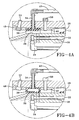
- Fig. 4A illustrates the seal 30 in an uninflated condition.
- Fig. 4B illustrates the seal 30 in an inflated condition. When inflated the seal 30 contacts the outer surface 20 of the drum 12.
- the seals 30, 32 are usually inflated to a pressure about 0.034474 MPa (5 psi) greater than the pressure which will be applied to the space 28. This allows the seals 30, 32 to withstand the pressure applied to the enclosed space 28. Thus if the space is pressurized to 0.310264 MPa (45 psi), the seals will be inflated to a pressure greater than 0.310264 MPa (45 psi), e.g., 0.344738 MPa (50 psi).
- the housing 14 also contains a housing pressure valve 52. Pressurized gas is controlled by the housing pressure valve 52 and is fed into the space 28 between the housing 12 and the drum 10 such that by opening the valve 52, the space 28 can be pressurized.
- a layer of uncured rubber 11 is applied on the outer surface 20 of the drum 12. Any conventional method for forming the inner liner 11 on the drum 12 may be used. In one method, the inner liner is separately formed in sheets and the sheet is wrapped around the drum and spliced in a manner that is well known in the art.
- the rubber layer can be formed of any composition that is useful in forming the inner liner of a tire. Rubber formulations that are useful for this purpose are well known in the art. These formulations will vary depending upon the nature and size of the tire that is constructed using the inner liner.
- One rubber composition that is useful in making the inner liner is a butyl rubber composition. Other examples are provided in US-A- 4,279,284.
- the layer may range from 1.27 to 6.35 mm (0.050 to 0.250 inch) thick but it is not limited to this.
- the seals 30, 32 at the end of the housing 14 are inflated to enclose the space 28 and create a sealed chamber that can be pressurized.
- air or another gas is fed into the space 28.
- the pressure applied is typically at least 0.275790 MPa (40 psi).
- the pressure is selected so that it is high enough to prevent vulcanization products from foaming (i.e., forming pores in) the inner liner but low enough to remain within the operating limit of the inflatable seals.
- the applied pressure is maintained as the heat exchange chamber 26 of the drum 12 is fed with a heated fluid.
- the heated fluid is steam that can be fed into the heat exchange chamber 26 through supply tubes 24.
- the heat source can be a fluid such as steam or another heat exchange fluid like hot oil.
- the heat exchange chamber could be heated by an electric heating element.
- the heat source heats the drum 12 which in turn heats the layer of the rubber 11 adjacent the outer surface 20 of the drum 12.
- the rubber is heated to about 121.1°C to 232.2°C (250 to 450°F) and more typically to about 131.8°C to 160°C (280 to 320°F).
- the layer of the rubber 11 adjacent to the drum 12 begins to cure from the heat as the heat penetrates the layer of rubber 11 from one side.
- the actual heating conditions will depend upon the formulation of the rubber composition that is being cured, its thickness and the cure depth profile that is desired.
- the cure profile that is produced in the inner liner will vary depending upon the size and shape of the tire and the tire molding process in which the inner liner is used.
- the outer surface of the inner liner will be cured less than the inner surface adjacent the drum.
- the outer surface may range in degree of cure from being essentially uncured to being nearly fully cured, e.g., about 0 to 98% cure.
- the inner surface may be essentially fully cured or cured 60 to 100%.
- One objective is to select a cure profile that provides enough cure to the inner surface that the liner can be used in a bladderless molding process and the outer surface remains sufficiently uncured to adhere the other components of the tire to the liner in the tire building process.
- the heat source is removed and a coolant is fed into the heat exchange chamber 26 to cool the drum, in turn cooling the layer of rubber 11 and effectively stopping any further curing of the rubber or slowing it to an insignificant rate.
- the coolant source can be fed into the heat exchange chamber 26 through the supply tubes 24 located on the inner surface 22 of the drum.
- the coolant source can be water. The water can be cooled to a temperature that is effective to stop the cure as quickly as is desired.
- the pressure applied to the rubber can be released. In one embodiment, this can be accomplished by turning off the housing pressure valve 52 and deflating the seals 30, 32. thereafter, the housing 14 is moved to its original position adjacent the drum 12.
- the partially cured layer of rubber 11 can be removed by peeling it from the drum surface, and applied to the next step of the tire building process.
- the cured side of the inner liner becomes gas and liquid impermeable, while the less cured or uncured side still holds the tacky properties that are helpful to add further components to the tire in the tire building process.
- the cured portion of the inner liner allows the molding of the rubber without the use of an air bladder because it is able to withstand the curing fluid in the molding process. In effect, the cured portion of the inner liner acts as a substitute for the curing bladder.
- the partially cured inner liner enjoys both the properties of a curing bladder, yet retains the tackiness properties desired to further add components of to build the tire.
Landscapes
- Physics & Mathematics (AREA)
- Health & Medical Sciences (AREA)
- Oral & Maxillofacial Surgery (AREA)
- Thermal Sciences (AREA)
- Engineering & Computer Science (AREA)
- Mechanical Engineering (AREA)
- Heating, Cooling, Or Curing Plastics Or The Like In General (AREA)
- Tyre Moulding (AREA)
Claims (10)
- Ein Verfahren zur Herstellung einer Innenisolierung für einen Reifen, umfassend die Schritte des:Formens einer Schicht aus unvulkanisiertem Kautschuk (11), wobei diese Schicht (11) eine erste Oberfläche und eine entgegengesetzte Oberfläche hat,Anlegens von Druck auf die Schicht Kautschuk (11),Erhitzens der Schicht Kautschuk (11) von der ersten Oberfläche her, um die Schicht an dieser Oberfläche auf einen höheren Vulkanisationsgrad zu vulkanisieren als an der entgegengesetzten Oberfläche;Abkühlens der Schicht Kautschuk (11); undWegnehmens des an die Schicht Kautschuk (11) angelegten Drucks, nachdem die Schicht abgekühlt hat.
- Das Verfahren von Anspruch 1, wobei die Schicht unvulkanisierten Kautschuks (11) auf einer Trommel (12) gebildet wird, mit einer Oberfläche der Schicht (11) benachbart zur Außenfläche (20) der Trommel (12).
- Das Verfahren von Anspruch 1 oder 2, wobei die Schicht unvulkanisierten Kautschuks (11) 1,27 bis 6,35 mm (0,050 bis 0,250 Zoll) dick ist.
- Das Verfahren von wenigstens einem der vorhergehenden Ansprüche, wobei der Schritt des Erhitzens einer Oberfläche der Schicht Kautschuk (11) durch Erhitzen der Trommel (12) und dadurch vorzugsweise Erhitzen der Oberfläche der Schicht Kautschuk (11) benachbart zu der Trommel (12) durchgeführt wird.
- Das Verfahren von wenigstens einem der vorhergehenden Ansprüche, wobei die Schicht Kautschuk (11) auf eine Temperatur von 121,1°C bis 232,2°C (250 bis 450°F) erhitzt wird.
- Das Verfahren von wenigstens einem der vorhergehenden Ansprüche, wobei die unvulkanisierte Schicht Kautschuk (11) für eine Zeit erhitzt wird, die ausreicht, um der Schicht Kautschuk (11) ein gewünschtes Vulkanisationsprofil zu verschaffen.
- Das Verfahren von wenigstens einem der vorhergehenden Ansprüche, wobei die Schicht unvulkanisierten Kautschuks (11) auf eine solche Temperatur und für eine solche Zeit erhitzt wird, dass ein Teil der Dicke der Schicht (11) teilvulkanisiert wird und ein anderer Teil der Dicke der Schicht (11) auf einen höheren Vulkanisationsgrad vulkanisiert wird.
- Ein Verfahren zum Vulkanisieren einer Innenisolierung eines Reifens, umfassend die Schritte des:Verschaffens einer Vorrichtung (10), welche eine Trommel (12) umfasst, wobei die Trommel (12) eine Innenfläche (22) und eine Außenfläche (20) aufweist; eine Wärmetauschkammer (26) an der Innenfläche (22) der Trommel (20); ein Gehäuse (14), das die Trommel (12) mit einem Raum (28) zwischen der Außenfläche (20) der Trommel (12) und dem Gehäuse (14) umgibt; einer aufpumpbaren Dichtung (30, 32) an jedem Ende des Gehäuses (14), sodass durch Aufblasen der Dichtung (30, 32) die Dichtung (30, 32) sich ausdehnt und den Raum (28) zwischen der Trommel (12) und dem Gehäuse (14) einschließt; einen Gaseinlass (34, 36) zum Zuführen eines Gases zu dem Raum (28) und Druckbeaufschlagen des Raums (28); eine Wärmequelle in Kommunikation mit der Wärmetauschkammer (26) zum Erhitzen der Trommel (12); und eine Kühlmittelquelle in Kommunikation mit der Wärmetauschkammer (26) zum Kühlen der Trommel (12);Anbringens einer Schicht unvulkanisierten Kautschuks (11) an der Außenfläche (20) der Trommel (12);Aufpumpens der Dichtung (30, 32) zum Einschließen des Raums (28) zwischen der Trommel (12) und dem Gehäuse (14);Zuführens eines Gases zu dem Raum (28) zur Druckbeaufschlagung des Raums (28) und der Schicht Kautschuk (11);Erhitzens der Trommel (12), dadurch Erhitzen der Schicht Kautschuk (11) von der Oberfläche benachbart zur Trommel (12) her, zum Vulkanisieren der Schicht (11) an dieser Oberfläche auf einen höheren Vulkanisationsgrad als an der entgegengesetzten Oberfläche;Kühlens der Trommel (12), wodurch die Schicht Kautschuk (11) gekühlt wird; undWegnehmens des Drucks in dem Raum (28), wenn die Schicht (11) abgekühlt ist.
- Eine Vorrichtung (10) zum Vulkanisieren einer Innenisolierung eines Reifens, umfassend:eine Trommel (12), wobei die Trommel (12) eine Innenfläche (22) und Außenfläche (20) aufweist;eine Wärmetauschkammer (26) an der Innenfläche (22) der Trommel (12);ein Gehäuse (14), das die Trommel (12) umgibt;einen Raum (28) zwischen der Außenfläche (20) der Trommel (12) und dem Gehäuse (14);eine aufpumpbare Dichtung (30, 32) an jedem Ende des Gehäuses (14) innerhalb des Gehäuses (14), sodass durch Aufpumpen der Dichtung (30, 32) die Dichtung (30, 32) sich ausdehnt und den Raum (28) zwischen der Trommel (12) und dem Gehäuse (14) einschließt;einen Gaseinlass (34, 36) zum Zuführen eines Gases zu dem Raum (28) und Druckbeaufschlagen des Raums (28);eine Wärmequelle in Kommunikation mit der Wärmetauschkammer (26) zum Erhitzen der Trommel (12); undeine Kühlmittelquelle in Kommunikation mit der Wärmetauschkammer (26) zum Kühlen der Trommel (12).
- Die Vorrichtung von Anspruch 9, dadurch gekennzeichnet, dass die Trommel (12) und das Gehäuse (14) zwecks Bewegung in Bezug zueinander auf einer Schiene (16) montiert sind.
Applications Claiming Priority (2)
| Application Number | Priority Date | Filing Date | Title |
|---|---|---|---|
| US331948 | 2002-12-30 | ||
| US10/331,948 US8114335B2 (en) | 2002-12-30 | 2002-12-30 | Partial depth-wise cure of a tire inner liner |
Publications (3)
| Publication Number | Publication Date |
|---|---|
| EP1435287A2 EP1435287A2 (de) | 2004-07-07 |
| EP1435287A3 EP1435287A3 (de) | 2005-05-25 |
| EP1435287B1 true EP1435287B1 (de) | 2007-03-07 |
Family
ID=32507365
Family Applications (1)
| Application Number | Title | Priority Date | Filing Date |
|---|---|---|---|
| EP03104896A Expired - Lifetime EP1435287B1 (de) | 2002-12-30 | 2003-12-22 | Tiefenabhängige Teilvernetzung eines Reifeninnenbelags |
Country Status (7)
| Country | Link |
|---|---|
| US (1) | US8114335B2 (de) |
| EP (1) | EP1435287B1 (de) |
| JP (1) | JP4436669B2 (de) |
| KR (1) | KR100985679B1 (de) |
| CN (1) | CN1513657A (de) |
| BR (1) | BR0306062A (de) |
| DE (1) | DE60312296T2 (de) |
Families Citing this family (8)
| Publication number | Priority date | Publication date | Assignee | Title |
|---|---|---|---|---|
| US7704343B2 (en) * | 2003-07-16 | 2010-04-27 | The Yokohama Rubber Co., Ltd. | Method of manufacturing pneumatic tire and tire building machine used therefor |
| BRPI0720648B1 (pt) * | 2006-12-29 | 2019-05-14 | Bridgestone Americas Tire Operations, Llc | Método para preparar um revestimento interno de pneu cru e pneu compreendendo um revestimento interno |
| US8597449B2 (en) * | 2010-11-24 | 2013-12-03 | The Goodyear Tire & Rubber Company | Method for recovering uncured rubber and tire including reclaimed rubber |
| US9315425B2 (en) | 2013-10-28 | 2016-04-19 | Universiti Brunei Darussalam | Macroporous ceramic body, method of manufacture and uses thereof |
| WO2016210406A1 (en) | 2015-06-25 | 2016-12-29 | Bridgestone Americas Tire Operations, Llc | Bladder rings for tire vulcanization mold |
| CN111037964B (zh) * | 2019-12-30 | 2021-07-23 | 永一橡胶有限公司 | 一种轮胎反包胶囊成型鼓及其使用方法 |
| EP4344864A1 (de) * | 2022-09-28 | 2024-04-03 | Bridgestone Europe NV/SA | Reifenherstellungsverfahren und -anlage |
| EP4344865A1 (de) | 2022-09-28 | 2024-04-03 | Bridgestone Europe NV/SA | Reifenherstellungsverfahren und -anlage |
Family Cites Families (21)
| Publication number | Priority date | Publication date | Assignee | Title |
|---|---|---|---|---|
| US1387381A (en) * | 1921-08-09 | Tire-vulcanizing method and apparatus | ||
| US2066265A (en) * | 1933-11-25 | 1936-12-29 | Wingfoot Corp | Method of curing tires |
| DE1250112B (de) * | 1962-12-05 | 1967-09-14 | Pirelli Societä per Azioni, Mailand (Italien) | Verfahren zum Herstellen eines Schutzstreifens für Fahrzeugluftreifen |
| US3933553A (en) * | 1973-01-05 | 1976-01-20 | Mildred Kelley Seiberling | Tires, etc |
| US4176702A (en) * | 1973-01-05 | 1979-12-04 | Mildred Kelly Seiberling | Tire treads and their manufacture |
| US4139405A (en) * | 1975-10-30 | 1979-02-13 | Mildred Kelley Seiberling | Selective electron irradiation precuring of treads in tire making processes |
| US4269644A (en) * | 1977-12-09 | 1981-05-26 | Prior Tire Enterprises Inc. | Cold recapping method for tires |
| US4233013A (en) * | 1978-05-16 | 1980-11-11 | The Firestone Tire & Rubber Company | Apparatus for producing continuous cured rubber strips |
| US4274897A (en) * | 1979-07-13 | 1981-06-23 | Barefoot Carlton K | Method and apparatus for vulcanizing tires |
| US5179156A (en) * | 1987-01-19 | 1993-01-12 | Sumitomo Chemical Company, Limited | Rubber composition |
| US5201975A (en) * | 1987-11-13 | 1993-04-13 | Bridgestone/Firestone Inc. | Tire manufacture |
| DE3832487C2 (de) | 1988-09-24 | 2000-04-20 | Uniroyal Englebert Gmbh | Verfahren zur Herstellung eines Fahrzeugluftreifens |
| US5228965A (en) * | 1990-10-30 | 1993-07-20 | Gould Inc. | Method and apparatus for applying surface treatment to metal foil |
| US5354195A (en) * | 1992-12-23 | 1994-10-11 | United Technologies Corporation | Composite molding apparatus for high pressure co-cure molding of lightweight honeycomb core composite articles having ramped surfaces utilizing low density, stabilized ramped honeycomb cores |
| US5645674A (en) * | 1993-03-11 | 1997-07-08 | Bridgestone Corporation | Methods for achieving improved bond strength between unvulcanized and vulcanized rubbers |
| TR199902228T2 (xx) | 1997-03-25 | 2000-07-21 | The Goodyear Tire & Rubber Company | Vulkanize astarl� pn�matik ta��t lastikleri ve astar�n kullan�m y�ntemi. |
| US6409959B1 (en) * | 1998-07-31 | 2002-06-25 | Pirelli Pneumatici S.P.A. | Process for manufacturing, moulding and curing tires for vehicle wheels |
| US6482282B1 (en) * | 1998-10-23 | 2002-11-19 | The Goodyear Tire & Rubber Company | Method for storage, handling and application of precured tire innerliners |
| BR9915561A (pt) * | 1998-11-25 | 2001-08-14 | Goodyear Tire & Rubber | Revestimento interno contìnuo, vulcanizado para pneus |
| DE19905643C2 (de) * | 1999-02-11 | 2001-05-03 | Continental Ag | Verfahren zur Herstellung eines Luftreifens |
| US6401524B1 (en) * | 2000-12-08 | 2002-06-11 | The Goodyear Tire & Rubber Company | Method of detecting steam expansion vessel leakage |
-
2002
- 2002-12-30 US US10/331,948 patent/US8114335B2/en not_active Expired - Fee Related
-
2003
- 2003-12-18 BR BR0306062-4A patent/BR0306062A/pt not_active IP Right Cessation
- 2003-12-22 EP EP03104896A patent/EP1435287B1/de not_active Expired - Lifetime
- 2003-12-22 DE DE60312296T patent/DE60312296T2/de not_active Expired - Fee Related
- 2003-12-26 JP JP2003434246A patent/JP4436669B2/ja not_active Expired - Fee Related
- 2003-12-29 KR KR1020030098782A patent/KR100985679B1/ko not_active Expired - Fee Related
- 2003-12-30 CN CNA2003101243661A patent/CN1513657A/zh active Pending
Also Published As
| Publication number | Publication date |
|---|---|
| EP1435287A3 (de) | 2005-05-25 |
| DE60312296D1 (de) | 2007-04-19 |
| EP1435287A2 (de) | 2004-07-07 |
| DE60312296T2 (de) | 2007-12-20 |
| BR0306062A (pt) | 2004-08-17 |
| JP2004209982A (ja) | 2004-07-29 |
| US20040123936A1 (en) | 2004-07-01 |
| JP4436669B2 (ja) | 2010-03-24 |
| US8114335B2 (en) | 2012-02-14 |
| KR100985679B1 (ko) | 2010-10-05 |
| CN1513657A (zh) | 2004-07-21 |
| KR20040060826A (ko) | 2004-07-06 |
Similar Documents
| Publication | Publication Date | Title |
|---|---|---|
| TW436434B (en) | Elastomeric innerliner, methods of manufacturing an elastomeric innerliner, method of manufacturing a tubeless, pneumatic tire, and a method of retreading a tire | |
| RU2235641C2 (ru) | Способ и устройство формования и вулканизации шин для колес транспортных средств | |
| EP0976533B1 (de) | Verfahren und Vorrichtung zum Formen und Vulkanisiern von Luftreifen | |
| RU2327569C2 (ru) | Способ и устройство для формования и вулканизации шины для колес транспортного средства | |
| US10259180B2 (en) | Process for manufacturing a tyre and toroidal support for carrying out said process | |
| US3729358A (en) | Apparatus for retreading tires | |
| EP1435287A2 (de) | Tiefenabhängige Teilvernetzung eines Reifeninnenbelags | |
| IE45076B1 (en) | Method for bonding tread strips to tire bodies | |
| US3779830A (en) | Apparatus for retreading tires | |
| US2791805A (en) | Liner sleeve for tire retreading mold | |
| KR930004043B1 (ko) | 블래더, 블래더리스타입 이중목적 타이어 가황기 | |
| EP1601521B1 (de) | Methode und vorrichtung zur herstellung von reifen für fahrzeugräder | |
| JP2000296523A (ja) | 車の車輪用タイヤの成形・硬化方法及びその装置 | |
| US3816217A (en) | Method and apparatus for retreading tires | |
| US3853666A (en) | Method and apparatus for retreading tires | |
| CN101060972B (zh) | 用于制造充气轮胎的方法和装置 | |
| US3779831A (en) | Apparatus for retreading tires | |
| JP7811147B2 (ja) | タイヤ加硫用ブラダのパンクを検出する方法 | |
| JP2009208400A (ja) | タイヤの製造方法及び製造装置 | |
| JP2005066848A (ja) | タイヤ加硫方法及びタイヤ加硫装置 | |
| CN115635719A (zh) | 轮胎硫化装置用容器 | |
| CZ339999A3 (cs) | Elastomerní mezivložka, způsob její výroby, způsob výroby bezdušové pneumatiky a způsob protektorování pneumatiky | |
| IE45079B1 (en) | Method and apparatus for bonding tread strips to tire bodies | |
| MXPA99008503A (en) | Vulcanized innerliner and method of utilizing the same for pneumatic tyres |
Legal Events
| Date | Code | Title | Description |
|---|---|---|---|
| PUAI | Public reference made under article 153(3) epc to a published international application that has entered the european phase |
Free format text: ORIGINAL CODE: 0009012 |
|
| AK | Designated contracting states |
Kind code of ref document: A2 Designated state(s): AT BE BG CH CY CZ DE DK EE ES FI FR GB GR HU IE IT LI LU MC NL PT RO SE SI SK TR |
|
| AX | Request for extension of the european patent |
Extension state: AL LT LV MK |
|
| PUAL | Search report despatched |
Free format text: ORIGINAL CODE: 0009013 |
|
| AK | Designated contracting states |
Kind code of ref document: A3 Designated state(s): AT BE BG CH CY CZ DE DK EE ES FI FR GB GR HU IE IT LI LU MC NL PT RO SE SI SK TR |
|
| AX | Request for extension of the european patent |
Extension state: AL LT LV MK |
|
| 17P | Request for examination filed |
Effective date: 20051125 |
|
| AKX | Designation fees paid |
Designated state(s): DE FR GB IT |
|
| GRAP | Despatch of communication of intention to grant a patent |
Free format text: ORIGINAL CODE: EPIDOSNIGR1 |
|
| GRAS | Grant fee paid |
Free format text: ORIGINAL CODE: EPIDOSNIGR3 |
|
| GRAA | (expected) grant |
Free format text: ORIGINAL CODE: 0009210 |
|
| AK | Designated contracting states |
Kind code of ref document: B1 Designated state(s): DE FR GB IT |
|
| REG | Reference to a national code |
Ref country code: GB Ref legal event code: FG4D |
|
| REF | Corresponds to: |
Ref document number: 60312296 Country of ref document: DE Date of ref document: 20070419 Kind code of ref document: P |
|
| ET | Fr: translation filed | ||
| PLBE | No opposition filed within time limit |
Free format text: ORIGINAL CODE: 0009261 |
|
| STAA | Information on the status of an ep patent application or granted ep patent |
Free format text: STATUS: NO OPPOSITION FILED WITHIN TIME LIMIT |
|
| 26N | No opposition filed |
Effective date: 20071210 |
|
| PGFP | Annual fee paid to national office [announced via postgrant information from national office to epo] |
Ref country code: GB Payment date: 20071106 Year of fee payment: 5 |
|
| PGFP | Annual fee paid to national office [announced via postgrant information from national office to epo] |
Ref country code: IT Payment date: 20081218 Year of fee payment: 6 |
|
| PGFP | Annual fee paid to national office [announced via postgrant information from national office to epo] |
Ref country code: FR Payment date: 20081205 Year of fee payment: 6 |
|
| PGFP | Annual fee paid to national office [announced via postgrant information from national office to epo] |
Ref country code: DE Payment date: 20081230 Year of fee payment: 6 |
|
| GBPC | Gb: european patent ceased through non-payment of renewal fee |
Effective date: 20081222 |
|
| PG25 | Lapsed in a contracting state [announced via postgrant information from national office to epo] |
Ref country code: GB Free format text: LAPSE BECAUSE OF NON-PAYMENT OF DUE FEES Effective date: 20081222 |
|
| REG | Reference to a national code |
Ref country code: FR Ref legal event code: ST Effective date: 20100831 |
|
| PG25 | Lapsed in a contracting state [announced via postgrant information from national office to epo] |
Ref country code: FR Free format text: LAPSE BECAUSE OF NON-PAYMENT OF DUE FEES Effective date: 20091231 |
|
| PG25 | Lapsed in a contracting state [announced via postgrant information from national office to epo] |
Ref country code: DE Free format text: LAPSE BECAUSE OF NON-PAYMENT OF DUE FEES Effective date: 20100701 |
|
| PG25 | Lapsed in a contracting state [announced via postgrant information from national office to epo] |
Ref country code: IT Free format text: LAPSE BECAUSE OF NON-PAYMENT OF DUE FEES Effective date: 20091222 |