EP1435339A2 - Procédé et dispositif de traitement de substrats organiques, de boues résiduaires et d'eaux usées - Google Patents
Procédé et dispositif de traitement de substrats organiques, de boues résiduaires et d'eaux usées Download PDFInfo
- Publication number
- EP1435339A2 EP1435339A2 EP04008188A EP04008188A EP1435339A2 EP 1435339 A2 EP1435339 A2 EP 1435339A2 EP 04008188 A EP04008188 A EP 04008188A EP 04008188 A EP04008188 A EP 04008188A EP 1435339 A2 EP1435339 A2 EP 1435339A2
- Authority
- EP
- European Patent Office
- Prior art keywords
- flow channel
- constriction
- inside diameter
- sludge
- sewage sludge
- Prior art date
- Legal status (The legal status is an assumption and is not a legal conclusion. Google has not performed a legal analysis and makes no representation as to the accuracy of the status listed.)
- Granted
Links
Images


Classifications
-
- C—CHEMISTRY; METALLURGY
- C02—TREATMENT OF WATER, WASTE WATER, SEWAGE, OR SLUDGE
- C02F—TREATMENT OF WATER, WASTE WATER, SEWAGE, OR SLUDGE
- C02F1/00—Treatment of water, waste water, or sewage
- C02F1/34—Treatment of water, waste water, or sewage with mechanical oscillations
-
- C—CHEMISTRY; METALLURGY
- C02—TREATMENT OF WATER, WASTE WATER, SEWAGE, OR SLUDGE
- C02F—TREATMENT OF WATER, WASTE WATER, SEWAGE, OR SLUDGE
- C02F3/00—Biological treatment of water, waste water, or sewage
- C02F3/02—Aerobic processes
- C02F3/12—Activated sludge processes
-
- C—CHEMISTRY; METALLURGY
- C12—BIOCHEMISTRY; BEER; SPIRITS; WINE; VINEGAR; MICROBIOLOGY; ENZYMOLOGY; MUTATION OR GENETIC ENGINEERING
- C12M—APPARATUS FOR ENZYMOLOGY OR MICROBIOLOGY; APPARATUS FOR CULTURING MICROORGANISMS FOR PRODUCING BIOMASS, FOR GROWING CELLS OR FOR OBTAINING FERMENTATION OR METABOLIC PRODUCTS, i.e. BIOREACTORS OR FERMENTERS
- C12M21/00—Bioreactors or fermenters specially adapted for specific uses
- C12M21/04—Bioreactors or fermenters specially adapted for specific uses for producing gas, e.g. biogas
-
- C—CHEMISTRY; METALLURGY
- C12—BIOCHEMISTRY; BEER; SPIRITS; WINE; VINEGAR; MICROBIOLOGY; ENZYMOLOGY; MUTATION OR GENETIC ENGINEERING
- C12M—APPARATUS FOR ENZYMOLOGY OR MICROBIOLOGY; APPARATUS FOR CULTURING MICROORGANISMS FOR PRODUCING BIOMASS, FOR GROWING CELLS OR FOR OBTAINING FERMENTATION OR METABOLIC PRODUCTS, i.e. BIOREACTORS OR FERMENTERS
- C12M27/00—Means for mixing, agitating or circulating fluids in the vessel
-
- C—CHEMISTRY; METALLURGY
- C12—BIOCHEMISTRY; BEER; SPIRITS; WINE; VINEGAR; MICROBIOLOGY; ENZYMOLOGY; MUTATION OR GENETIC ENGINEERING
- C12M—APPARATUS FOR ENZYMOLOGY OR MICROBIOLOGY; APPARATUS FOR CULTURING MICROORGANISMS FOR PRODUCING BIOMASS, FOR GROWING CELLS OR FOR OBTAINING FERMENTATION OR METABOLIC PRODUCTS, i.e. BIOREACTORS OR FERMENTERS
- C12M29/00—Means for introduction, extraction or recirculation of materials, e.g. pumps
- C12M29/06—Nozzles; Sprayers; Spargers; Diffusers
-
- C—CHEMISTRY; METALLURGY
- C12—BIOCHEMISTRY; BEER; SPIRITS; WINE; VINEGAR; MICROBIOLOGY; ENZYMOLOGY; MUTATION OR GENETIC ENGINEERING
- C12M—APPARATUS FOR ENZYMOLOGY OR MICROBIOLOGY; APPARATUS FOR CULTURING MICROORGANISMS FOR PRODUCING BIOMASS, FOR GROWING CELLS OR FOR OBTAINING FERMENTATION OR METABOLIC PRODUCTS, i.e. BIOREACTORS OR FERMENTERS
- C12M41/00—Means for regulation, monitoring, measurement or control, e.g. flow regulation
- C12M41/02—Means for regulation, monitoring, measurement or control, e.g. flow regulation of foam
-
- C—CHEMISTRY; METALLURGY
- C12—BIOCHEMISTRY; BEER; SPIRITS; WINE; VINEGAR; MICROBIOLOGY; ENZYMOLOGY; MUTATION OR GENETIC ENGINEERING
- C12M—APPARATUS FOR ENZYMOLOGY OR MICROBIOLOGY; APPARATUS FOR CULTURING MICROORGANISMS FOR PRODUCING BIOMASS, FOR GROWING CELLS OR FOR OBTAINING FERMENTATION OR METABOLIC PRODUCTS, i.e. BIOREACTORS OR FERMENTERS
- C12M45/00—Means for pre-treatment of biological substances
- C12M45/02—Means for pre-treatment of biological substances by mechanical forces; Stirring; Trituration; Comminuting
-
- C—CHEMISTRY; METALLURGY
- C02—TREATMENT OF WATER, WASTE WATER, SEWAGE, OR SLUDGE
- C02F—TREATMENT OF WATER, WASTE WATER, SEWAGE, OR SLUDGE
- C02F2303/00—Specific treatment goals
- C02F2303/04—Disinfection
-
- C—CHEMISTRY; METALLURGY
- C02—TREATMENT OF WATER, WASTE WATER, SEWAGE, OR SLUDGE
- C02F—TREATMENT OF WATER, WASTE WATER, SEWAGE, OR SLUDGE
- C02F2303/00—Specific treatment goals
- C02F2303/12—Prevention of foaming
-
- C—CHEMISTRY; METALLURGY
- C02—TREATMENT OF WATER, WASTE WATER, SEWAGE, OR SLUDGE
- C02F—TREATMENT OF WATER, WASTE WATER, SEWAGE, OR SLUDGE
- C02F3/00—Biological treatment of water, waste water, or sewage
- C02F3/28—Anaerobic digestion processes
-
- Y—GENERAL TAGGING OF NEW TECHNOLOGICAL DEVELOPMENTS; GENERAL TAGGING OF CROSS-SECTIONAL TECHNOLOGIES SPANNING OVER SEVERAL SECTIONS OF THE IPC; TECHNICAL SUBJECTS COVERED BY FORMER USPC CROSS-REFERENCE ART COLLECTIONS [XRACs] AND DIGESTS
- Y02—TECHNOLOGIES OR APPLICATIONS FOR MITIGATION OR ADAPTATION AGAINST CLIMATE CHANGE
- Y02E—REDUCTION OF GREENHOUSE GAS [GHG] EMISSIONS, RELATED TO ENERGY GENERATION, TRANSMISSION OR DISTRIBUTION
- Y02E50/00—Technologies for the production of fuel of non-fossil origin
- Y02E50/30—Fuel from waste, e.g. synthetic alcohol or diesel
-
- Y—GENERAL TAGGING OF NEW TECHNOLOGICAL DEVELOPMENTS; GENERAL TAGGING OF CROSS-SECTIONAL TECHNOLOGIES SPANNING OVER SEVERAL SECTIONS OF THE IPC; TECHNICAL SUBJECTS COVERED BY FORMER USPC CROSS-REFERENCE ART COLLECTIONS [XRACs] AND DIGESTS
- Y02—TECHNOLOGIES OR APPLICATIONS FOR MITIGATION OR ADAPTATION AGAINST CLIMATE CHANGE
- Y02W—CLIMATE CHANGE MITIGATION TECHNOLOGIES RELATED TO WASTEWATER TREATMENT OR WASTE MANAGEMENT
- Y02W10/00—Technologies for wastewater treatment
- Y02W10/10—Biological treatment of water, waste water, or sewage
Definitions
- the device relates to a method for the treatment of filamentous and flocculating waste water containing microorganisms, sewage sludge or in Biogas plants used organic substrates to reduce or Avoid the formation of expanded sludge, floating sludge and / or foam.
- Wastewater treatment uses biomass that is used for cleaning microorganisms used, separated from the purified waste water becomes.
- the biomass is usually combined in one Secondary clarifier separated by sedimentation and partially or completely returned to the aeration tank.
- Trouble-free operation of a sewage treatment plant with a biological cleaning stage therefore requires a well sedimenting Biomass or a well sedimenting activated sludge.
- the biomass used in the aeration tank is a mixed biocenosis various microorganisms.
- the mixed biocenosis are among others contain thready bacteria or thread bacteria and flocculating bacteria.
- non-sedimenting or floating Sludge aggregates occur with an increased growth of filamentous Bacteria, which then aggregate into a thread network. This thread braid significantly hinders the thickening and settling process of the activated sludge.
- the floating sludge aggregates consist mainly of expanded sludge, swimming mud and foam.
- a stable operation of a biological sewage treatment plant is dependent on the formation of Bulking sludge, swimming sludge or foam very difficult or not possible.
- DE 195 17 381 C1 discloses a further device for destroying cells Structures in sludges from biological treatment plants using a Ultrasound exposure known.
- the swelling and floating sludge is comminuted using an agitator ball mill, a shear gap, an ultrasound and a high-pressure homogenizer.
- an energy input of at least about 1000 kJ / m 3 sludge is required.
- the object of the invention is to provide a method and a device, that is easy to use and inexpensive to operate effective in the formation of non-sedimenting sludge aggregates Sewage treatment plants, biogas reactors etc. reduced or prevented.
- the object underlying the invention is achieved by a method for Treatment of filamentous and flocculating microorganism-containing wastewater, Sewage sludge or organic substrates used in biogas plants Reduction or prevention of the formation of bulking sludge, swimming sludge and / or foam, the waste water, the sewage sludge or the organic Substrates guided in a flow channel and one in the flow channel Shear stress that is sufficient to determine the relative ratio of the number from filamentous microorganisms to flake-forming microorganisms humiliate, is or will be resolved.
- the invention is essentially related to sewage treatment plants described.
- the invention is in no way limited to sewage treatment plants. Rather, the invention can be used in other biological plants, in which filamentous and flocculating microorganisms in a mixed biocenosis exist and work together.
- the invention is also for example Biogas reactors and anaerobic fermenters can be used. In this respect, the following explanations accordingly for biogas reactors and Anaerobic fermenter.
- the waste water is preferably an activated sludge or Mixed biocenosis in biological sewage plants.
- the wastewater is preferably activated sludge or a mixed biocenosis, in a shear stress flow channel subject to hydrodynamically generated shear fields.
- the shear fields arise from wastewater in the flow channel, preferably Activated sludge or a mixed biocenosis, occurring Velocity.
- the shear stress leads to a comminution or fragmentation of long-stranded microorganisms formed sludge aggregates or Yarn braids. Furthermore, in these sludge aggregates trapped or adhering finely distributed gas bubbles are released. This in The gas bubbles contained in the untreated sludge aggregates contribute to one Deterioration of the sedimentation behavior of the sludge aggregates.
- the on the filamentous bacteria contained in the mixed biocenosis by the generated shear field stress leads in particular to changes in the Metabolism of the filamentous bacteria, causing a change in the Growth kinetics in the filamentous microorganisms or bacteria leads.
- the Growth of filamentous microorganisms is significantly reduced.
- the change in metabolism of filamentous microorganisms is particular on the stimulation of protective mechanisms against that by the applied shear stress due to stress.
- the secreted extracellular polymeric substances advantageously bring about a Adhesion of the sludge aggregates crushed in the shear field. This adhesion works against the formation of too small sludge particles that are not or too slowly sediment, and leads to an advantageous flocculation and thus to the desired sedimentation of the mixed biocenosis.
- Microorganisms in the mixed biocenosis or sewage sludge change in favor of the flake-forming microorganisms.
- An increase in Ratio of flocculating bacteria to filamentous bacteria in the Mixed biocenosis favors sedimentation of the sludge aggregates.
- the shear stress is preferred by a turbulent flow in the Flow channel generated. It is further preferred that in the flow channel at least one constriction is arranged through which the waste water is led.
- the wastewater in the flow channel is highly turbulent.
- the Reynolds number of the turbulent wastewater or the mixed biocenosis is preferably at least 100,000, more preferably at least 180,000, still further preferably at least 250,000, more preferably at least 500,000.
- the wastewater preferably activated sludge or a mixed biocenosis
- the at least one constriction can be on the pressure side as well as on the suction side Flow channel may be arranged.
- the flow rate of the Sewage when passing through the constriction in the flow channel below decreasing pressure increases until vapor pressure is reached, which is in the form of Trains cavitation.
- Cavitation is the formation of cavities in liquids and their Movement.
- the cavity can be created by a local vacuum phase, Shear stresses or an energy input into the liquid.
- In the resulting bubbles diffuse the gases dissolved in the liquid into it.
- the pressure in the liquid rises again, they collapse Gas bubbles due to the external pressure.
- the Bladder content so strongly compressed that high pressures, up to some 1000 bar, and high temperatures, up to several 1000 K, are generated locally.
- the gas will ionized in the bladder and radicals develop.
- the bladder emits shock waves and, if so, during the collapse it is near solid surfaces, a liquid jet that through the bladder.
- the shock waves emitted by the bubbles and Liquid jets have the power to agglomerate particles such as Sludge aggregates to dissolve as well as macromolecules and bacterial cell walls break.
- the method according to the invention occurs preferred to a common occurrence of shear stress and Cavitation.
- the shear stress generated, for example, by a highly turbulent flow as well as the one preferably generated by the narrowing in the flow channel Cavitation is extremely advantageous in the method according to the invention together.
- the shear stress and the cavitation particularly affect the larger filamentous microorganisms or on those of filamentous microorganisms formed braids.
- the filamentous microorganisms become partial destroyed by breaking open the cell membranes. To a large extent comes it leads to a shortening of the filaments and thus to a breakup or one Shredding of the thread braids.
- the flake-forming bacteria through the The method according to the invention is not destroyed. Furthermore, there is none essential change in cell metabolism, so that the growth kinetics of flake-forming microorganisms are not significantly impaired or not is changed significantly.
- the method according to the invention thus performs in With regard to the different growth kinetics of thread and flocculating microorganisms to an advantageous change in Composition of the mixed biocenosis. This by the invention Changes in the bacterial composition caused by the process therefore result for a recovery of the sewage sludge.
- the duration of the cavitation is and thus the exposure time of the cavitation to the wastewater, or the Mixed biocenosis adjustable.
- the duration of the cavitation can be controlled. If the after the narrowing arranged flow channel is extended, the lengthens Duration of exposure to the wastewater, preferably the activated sludge or Mixed culture.
- the ratio of the inner diameter of the flow channel before the constriction, based on the flow direction of the waste water, to the inside diameter of the Flow channel after the constriction can, for example, about 5: 1 to about 1.2: 1, more preferably 3: 1 to 1.5: 1, very preferably 2: 1.
- the ratio of the smallest inside diameter of the constriction to that Inner diameter of the downstream of the constriction Flow channel can be, for example, 1: 1.2 to 1: 3, preferably 1: 2.
- the flow channel can be designed as a pipeline.
- the constriction provided in the flow channel can be as Nozzle, preferably in the geometry of a Laval nozzle.
- the object underlying the invention is further achieved by a Device for the treatment of filamentous and flaky microorganism-containing Wastewater, sewage sludge or used in biogas plants organic substrates to reduce or prevent the formation of Expanded sludge, floating sludge and / or foam, the device being a at least one narrowing flow channel and a device to convey waste water, sewage sludge or organic substrates through the Has flow channel, solved.
- the at least one constriction have a section converging and diverging inner diameter, wherein, referred on the flow direction of the waste water, preferably activated sludge or a Mixed biocenosis, the section with converging inner diameter in front of the Section with a diverging inner diameter is arranged.
- the flow channel can, for example, refer to the direction of flow of the Wastewater, initially conical to a minimum Expand inside diameter and then conical.
- the narrowing is preferably a nozzle that has two flow channels, preferably pipes, connects with each other.
- the narrowing or the Nozzle so designed that the length of the section converges Inner diameter is shorter than the length of the section with diverging Inner diameter.
- the geometric configuration of the constriction or the nozzle therefore, not symmetrical to the section with the least Inner diameter of the constriction or the nozzle.
- the asymmetrical design of the nozzle desired cavitation can be set so that a for the purpose of Avoiding bulking sludge, floating sludge and / or foam suitable Cavitation is generated.
- the nozzle has the geometry of a Laval nozzle on.
- downstream of the constriction or the nozzle in the flow channel Throttle for example a slide, arranged downstream of the constriction or the nozzle in the flow channel Throttle. This can be done with this choke Occurrence of cavitation can also be controlled.
- Gas bubbles entering the flow channel can have a damping effect exercise on cavitation.
- Waste water is preferred degassed during conveying into the flow channel, for example by Use of a pump, preferably a submersible pump, in one submerged shaft.
- FIG. 1 shows a schematic representation of the device according to the invention.
- the pump (1) pumps waste water, preferably activated sludge or a Mixed biocenosis, e.g. from an aeration tank or a clarifier (not shown), via a pipeline (2) through a nozzle (3) into a pipeline (4).
- a throttle (5) can be provided in the pipeline (4). That dealt with Waste water subsequently arrives from the pipeline (4) via a Dispenser (6) preferably back into the withdrawal basin, i.e. for example. the aeration tank or the secondary clarifier.
- the dispenser (6) also in another Collection basins are given.
- the pump (1) can both in front of the nozzle (3) and after the nozzle (3) Pipe (2) or (4) can be arranged.
- the pipe (2) has one Inside diameter, which is preferably larger than the inside diameter of the Pipe (4), the inner diameter of the pipe (4) being larger than that smallest inside diameter of the nozzle (3).
- any pump suitable for use in a clarifier can be used as the pump (1) Pump can be used.
- the one arranged on the outflow side of the nozzle (3) Pipeline (4) causes due to the in relation to the upstream to the nozzle (3) arranged pipe (2) of reduced internal diameter an extended Duration of action of the cavitation generated in the nozzle (3) on the waste water or Mixed culture.
- the length of the pipeline (4) can depend on the desired duration of action of the cavitation can be set. For example. can the The length of the pipeline (4) can be variably adjustable. As a result, a desired shortening of the filament length of filamentous bacteria as well reliable release of the in through the filamentous microorganisms generated gas mesh enclosed gas bubbles can be achieved. Farther is caused by the stress on the filamentous microorganisms Growth slowed.
- the exposure time of the cavitation can include over the length of the downstream side of the nozzle (3) arranged pipeline (4) can be controlled. Furthermore, the The formation of cavitation bubbles also through the throttle valve (5) adjustable pressure in the pipeline (4) can be controlled.
- the Dispensing device (6) which is preferably designed as a spray nozzle, causes Delivery of the treated mixed biocenosis from the device according to the invention escape of the gas bubbles released from the sludge aggregates.
- a confuser can be arranged in front of the nozzle (3), which has the inside diameter the pipeline (2) supplying the waste water, i.e. the upstream to the nozzle arranged pipe (2), reduced. This will make the transition between supply pipe (2) and nozzle (3) improved.
- the nozzle (3) and the throttle valve (5) Arrange the diffuser that the inner diameter of the nozzle (3) downstream pipe (4) expanded.
- the pressure in the wastewater preferably activated sludge or a mixed biocenosis, and increases the cavitation completed. This can cause cavitation, i.e. an impact of Cavitation bubbles on the throttle valve (5) and consequently damage. e.g. abrasion on the throttle valve (5) can be reliably prevented.
- the inside diameter of the pipeline (4) is preferably after the diffuser an inner diameter that is approximately the inner diameter of the upstream of the nozzle (3) arranged pipeline (2) corresponds.
- the length of the pipe (4) between the nozzle (3) and the diffuser can be designed to be changeable, for example telescopic his.
- nozzles (3) for example two or three Nozzles to be arranged one behind the other in a piping system. It has however, has shown that a reduction in bulking sludge that has occurred swimming mud and / or foam or avoiding the occurrence of Bulking sludge, floating sludge and / or foam through the invention Design is already achieved with a nozzle (3).
- the device according to the invention is surprisingly constructive simple.
- the method according to the invention or the one according to the invention Devices are therefore extremely advantageous for one maintenance-free and therefore inexpensive operation. Is advantageous for the operation no trained personnel required.
- the present invention can be used advantageously for both large and small wastewater treatment plants.
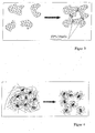
- Figure 2 shows a schematic representation of the release of in Sludge trapped or attached gas bubbles through A shear field is released from the sludge aggregates become. By releasing those trapped in the sludge aggregates or attached gas bubbles, the buoyancy of the sludge aggregates becomes essential reduced.
- the nozzle (3) When flowing through the waste water, preferably the activated sludge or Mixed biocenosis, the nozzle (3) continues to reduce the pressure in the wastewater passing through, resulting in a detachment of the gas bubbles from the Further promotes sludge aggregates. That is, the interaction of the through the Nozzle (3) in the wastewater induced turbulence with the decrease in pressure leads to a desired degassing of the sludge aggregates or release the attached or enclosed gas bubbles.
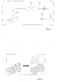
- FIG 3 shows the secretion of extracellular polymeric substances (EPS) caused by filamentous microorganisms improved flocculation of crushed sludge aggregates.
- EPS extracellular polymeric substances
- Figure 4 shows schematically the shortening of the length of the filaments of filaments Microorganisms using the method according to the invention. Next The shortening of the filament length also becomes the thread braid that is formed broken up.
- Figure 5 shows the influence of the inventive method on the Growth kinetics of flocculating microorganisms and filamentous or filiform microorganisms.
- Figure 5 shows that the growth rate of flake-forming microorganisms by the inventive method or is not significantly influenced.
- the method according to the invention has a significant influence on the Growth rate of filamentous microorganisms.
- the device according to the invention applied shear field and preferably If cavitation occurs, the growth of filamentous microorganisms becomes clear against flocculating microorganisms. This leads to a desired change in the relative composition of the mixed biocenosis. The relative ratio of filamentous microorganisms to flaky ones Microorganisms are degraded.
- FIG. 6 and FIG. 7 show measurement curves measured in an experimental sewage treatment plant were.
- the process according to the invention was carried out on a sewage treatment plant with approximately 12,000 connected population equivalents.
- the wastewater in the inlet this sewage treatment plant was heavily polluted with waste water from the textile industry and has led to major swelling and floating sludge problems for more than 10 years.
- the sludge volume index (ISV) was often above a value of 120 ml / g.
- the one that forms on the secondary clarifier Mud blanket was removed up to three times a day.
- the thickness of the swimming mud blanket could grow up to 5 cm and more.
- the device of the invention was directly in the aeration tank Sewage treatment plant arranged. Within the first two weeks, the Device operated according to the invention only 4 hours a day (performance of Pump 3.75 kW with a volume flow of 10.6 I / s).
- the inside diameter the pipeline in front of the nozzle was 100 mm
- the inside diameter of the pipeline arranged after the nozzle was 50 mm.
- the narrowest diameter of the nozzle used was 25 mm.
- the device according to the invention was switched to continuous operation and the energy input was increased to about 350 kJ / m 3 of mixed biocenosis (FIG. 6).
- the sludge volume index (ISV) which is the volume of sedimented sludge of 1 l content after 30 min. sedimentation, based on the Initial concentration describes is after increasing the energy input dropped below clearly 100 ml / g. With values over 120 ml / g it can be too considerable problems with the settling properties of the expanded sludge in the Clarifiers come.
- the sludge volume index had a value of approx. 80 ml / g and held this value upright for the coming weeks. This value is significantly below the threshold value of 120 ml / g, from which an expanded sludge behavior can be expected is. There was one in both the aeration tank and in the secondary clarifier significant reduction of the sludge volume index to about 80 ml / g.
- the energy input into the mixed biocenosis can be significantly less than 1,000 kJ / m 3 in order to avoid the occurrence of swelling and floating sludge.
- the energy input can range, for example, from about 200 kJ / m 3 mixed biocenosis to about 800 kJ / m 3 mixed biocenosis, preferably from about 250 kJ / m 3 mixed biocenosis to 600 kJ / m 3 Mixed biocenosis, more preferably from about 300 kJ / m 3 to about 500 kJ / m 3 mixed biocenosis.
- the speed of the wastewater conveyed through the pipeline (4) or the mixed biocenosis is in a range from about 3 m / s to 10 m / s, preferably from about 4 m / s to 8 m / s, more preferably from about 5 m / s to 7 m / s.
- FIG. 7 shows that there is also a process parameter Stabilization came, i.e. the inventive method to a stable Operation of the pilot plant.
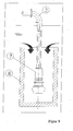
- FIG 8 shows one in a below the surface of the mixed biocenosis arranged shaft (8) arranged pump (7).
- the shaft (8) is in the sense of the invention as a submerged shaft (8).
- a pump (7) is arranged, the waste water, preferably the Activated sludge or the mixed biocenosis in the pipeline (2) promotes.
- a pump (7) and the inner walls of the submerged shaft (8) form one Degassing zone. In the degassing zone are at least partially in the Wastewater or the mixed biocenosis entrained or contained gas bubbles severed and released by the open towards the surface Escape the shaft.
Landscapes
- Life Sciences & Earth Sciences (AREA)
- Engineering & Computer Science (AREA)
- Chemical & Material Sciences (AREA)
- Health & Medical Sciences (AREA)
- Organic Chemistry (AREA)
- Zoology (AREA)
- Wood Science & Technology (AREA)
- Bioinformatics & Cheminformatics (AREA)
- Genetics & Genomics (AREA)
- Microbiology (AREA)
- Biotechnology (AREA)
- Biochemistry (AREA)
- General Health & Medical Sciences (AREA)
- General Engineering & Computer Science (AREA)
- Biomedical Technology (AREA)
- Sustainable Development (AREA)
- Molecular Biology (AREA)
- Mechanical Engineering (AREA)
- Environmental & Geological Engineering (AREA)
- Hydrology & Water Resources (AREA)
- Water Supply & Treatment (AREA)
- General Chemical & Material Sciences (AREA)
- Oil, Petroleum & Natural Gas (AREA)
- Analytical Chemistry (AREA)
- Biodiversity & Conservation Biology (AREA)
- Activated Sludge Processes (AREA)
- Treatment Of Sludge (AREA)
- Physical Water Treatments (AREA)
- Separation Using Semi-Permeable Membranes (AREA)
- Purification Treatments By Anaerobic Or Anaerobic And Aerobic Bacteria Or Animals (AREA)
- Revetment (AREA)
- Prevention Of Fouling (AREA)
- Biological Treatment Of Waste Water (AREA)
Applications Claiming Priority (3)
| Application Number | Priority Date | Filing Date | Title |
|---|---|---|---|
| DE2001155161 DE10155161A1 (de) | 2001-11-12 | 2001-11-12 | Verfahren und Vorrichtung zur Behandlung von Abwasser, Klärschlamm und organischen Substraten |
| DE10155161 | 2001-11-12 | ||
| EP20020781155 EP1409414B1 (fr) | 2001-11-12 | 2002-11-08 | Procede et dispositif de traitement de substrats organiques, de boues residuaires et d'eaux usees |
Related Parent Applications (3)
| Application Number | Title | Priority Date | Filing Date |
|---|---|---|---|
| EP02781155.3 Division | 2002-11-08 | ||
| EP20020781155 Division-Into EP1409414B1 (fr) | 2001-11-12 | 2002-11-08 | Procede et dispositif de traitement de substrats organiques, de boues residuaires et d'eaux usees |
| EP20020781155 Division EP1409414B1 (fr) | 2001-11-12 | 2002-11-08 | Procede et dispositif de traitement de substrats organiques, de boues residuaires et d'eaux usees |
Publications (3)
| Publication Number | Publication Date |
|---|---|
| EP1435339A2 true EP1435339A2 (fr) | 2004-07-07 |
| EP1435339A3 EP1435339A3 (fr) | 2004-07-28 |
| EP1435339B1 EP1435339B1 (fr) | 2007-03-07 |
Family
ID=7705240
Family Applications (3)
| Application Number | Title | Priority Date | Filing Date |
|---|---|---|---|
| EP04008187A Expired - Lifetime EP1440942B8 (fr) | 2001-11-12 | 2002-11-08 | Dispositif de traitement de substrats organiques, de boues résiduaires et d'eaux usées |
| EP20040008188 Expired - Lifetime EP1435339B1 (fr) | 2001-11-12 | 2002-11-08 | Procédé et dispositif de traitement de substrats organiques, de boues résiduaires et d'eaux usées |
| EP20020781155 Expired - Lifetime EP1409414B1 (fr) | 2001-11-12 | 2002-11-08 | Procede et dispositif de traitement de substrats organiques, de boues residuaires et d'eaux usees |
Family Applications Before (1)
| Application Number | Title | Priority Date | Filing Date |
|---|---|---|---|
| EP04008187A Expired - Lifetime EP1440942B8 (fr) | 2001-11-12 | 2002-11-08 | Dispositif de traitement de substrats organiques, de boues résiduaires et d'eaux usées |
Family Applications After (1)
| Application Number | Title | Priority Date | Filing Date |
|---|---|---|---|
| EP20020781155 Expired - Lifetime EP1409414B1 (fr) | 2001-11-12 | 2002-11-08 | Procede et dispositif de traitement de substrats organiques, de boues residuaires et d'eaux usees |
Country Status (11)
| Country | Link |
|---|---|
| US (1) | US7056437B2 (fr) |
| EP (3) | EP1440942B8 (fr) |
| JP (1) | JP4576118B2 (fr) |
| KR (1) | KR100765421B1 (fr) |
| AT (3) | ATE305904T1 (fr) |
| DE (5) | DE10155161A1 (fr) |
| DK (1) | DK1409414T3 (fr) |
| ES (1) | ES2231728T3 (fr) |
| PT (1) | PT1409414E (fr) |
| RU (1) | RU2283285C2 (fr) |
| WO (1) | WO2003042109A1 (fr) |
Families Citing this family (23)
| Publication number | Priority date | Publication date | Assignee | Title |
|---|---|---|---|---|
| EP1651576A2 (fr) * | 2003-07-28 | 2006-05-03 | Otv S.A. | Systeme et procede pour traitement ameliore des eaux usees |
| EP1658237B1 (fr) | 2003-08-29 | 2010-08-25 | Bionik GmbH - Innovative Technik für die Umwelt | Procede permettant la desintegration de substances organiques particulaires dans des suspensions de microorganismes |
| DE10343748B4 (de) * | 2003-08-29 | 2005-11-10 | BIONIK GmbH - Innovative Technik für die Umwelt | Verfahren zum Zerkleinern partikulärer organischer Substanzen in Suspensionen von Mikroorganismen |
| DE10343602A1 (de) * | 2003-09-20 | 2005-04-14 | Schmid, Andreas, Dr.-Ing. M.Sc. | Vorrichtung und Verfahren zur Behandlung eines Mediums wie Abwasser, Klärschlamm oder dergleichen |
| DE102004009636B4 (de) * | 2004-02-27 | 2007-03-01 | Schmid, Andreas, Dr.-Ing. | Verfahren und Vorrichtung zur Behandlung von schadstoffbelastetem Wasser |
| DE202005000875U1 (de) * | 2005-01-20 | 2006-06-01 | BIONIK GmbH - Innovative Technik für die Umwelt | Vorrichtung zum Zerkleinern partikulärer organischer Substanzen in Suspensionen von Mikroorganismen in einem Trägermedium, insbesondere in Abwässern |
| DE102005045170A1 (de) * | 2005-09-21 | 2007-03-29 | Nyhuis, Geert, Dr.-Ing. | Verfahren und Vorrichtung zur biologischen Abwasserreinigung im Belebungsverfahren |
| US20080099410A1 (en) * | 2006-10-27 | 2008-05-01 | Fluid-Quip, Inc. | Liquid treatment apparatus and methods |
| DE102007007721A1 (de) | 2007-02-16 | 2008-08-21 | BIONIK GmbH - Innovative Technik für die Umwelt | Verfahren und Vorrichtung zur Behandlung von Klärschlamm, Abwasser oder einer Suspension partikulärer Substanzen |
| US20080277264A1 (en) * | 2007-05-10 | 2008-11-13 | Fluid-Quip, Inc. | Alcohol production using hydraulic cavitation |
| KR100866620B1 (ko) | 2007-05-15 | 2008-11-04 | 삼창기업 주식회사 | 수리동력학적 캐비테이션을 이용한 슬러지 전처리 장치 |
| US8268136B2 (en) * | 2007-12-20 | 2012-09-18 | McCutchen, Co. | Electrohydraulic and shear cavitation radial counterflow liquid processor |
| US20090200176A1 (en) * | 2008-02-07 | 2009-08-13 | Mccutchen Co. | Radial counterflow shear electrolysis |
| US7757866B2 (en) * | 2007-12-20 | 2010-07-20 | Mccutchen Co. | Rotary annular crossflow filter, degasser, and sludge thickener |
| US8753505B2 (en) * | 2008-06-27 | 2014-06-17 | Fluid-Quip, Inc. | Liquid treatment apparatus and method for using same |
| FR2950047B1 (fr) * | 2009-09-17 | 2013-02-22 | Isb Water | Station d'epuration a boue activee. |
| DE102009059947A1 (de) * | 2009-12-22 | 2011-06-30 | BIONIK GmbH - Innovative Technik für die Umwelt, 65232 | Verfahren zur Erhöhung der Gasausbeute in einer Gärvorrichtung, insbesondere einer Biogasanlage oder einem Fermenter, sowie Verwendung einer Vorrichtung zur Durchführung eines solchen Verfahrens |
| JP5627313B2 (ja) * | 2010-06-22 | 2014-11-19 | 敬一郎 浅岡 | 有機性排水処理装置 |
| EP2636650A1 (fr) * | 2012-03-09 | 2013-09-11 | MCI Management Center Innsbruck - Internationale Hochschule GmbH | Installation et procédé biologique avec traitement de gaz au moins partiellement ionisé |
| US9777292B2 (en) | 2013-12-05 | 2017-10-03 | Arisdyne Systems, Inc. | Methods for treating biosolids sludge with cavitation |
| US10233132B2 (en) * | 2015-10-19 | 2019-03-19 | Oleksandr Galaka | Organic or organo-mineral fertilizers, method of producing thereof and production unit therefor |
| KR20180100583A (ko) * | 2016-01-06 | 2018-09-11 | 베올리아 워터 솔루션스 앤드 테크놀로지스 서포트 | 혐기성 바이오리액터의 기체 분리기의 현장 클리닝을 위한 프로세스 및 장치 |
| US10537840B2 (en) | 2017-07-31 | 2020-01-21 | Vorsana Inc. | Radial counterflow separation filter with focused exhaust |
Family Cites Families (35)
| Publication number | Priority date | Publication date | Assignee | Title |
|---|---|---|---|---|
| DE2652229B2 (de) | 1976-11-16 | 1979-03-22 | Boehringer Mannheim Gmbh, 6800 Mannheim | Verfahren zur biologischen Abwasserreinigung und Anlage zu seiner Durchführung |
| SU719702A2 (ru) | 1977-01-04 | 1980-03-05 | Институт Механики Ан Украинской Сср, Днепропетровское Отделение | Генератор колебаний давлени воды |
| DE2757742B2 (de) * | 1977-12-23 | 1979-10-18 | Linde Ag, 6200 Wiesbaden | Verfahren zur biologischen Reinigung von Abwasser |
| DE3428535A1 (de) * | 1984-08-02 | 1986-02-13 | Siekmann, Helmut E., Prof.Dr.-Ing., 1000 Berlin | Verfahren und vorrichtung, insbesondere zur konditionierung von abwaesserschlaemmen |
| SU1404467A1 (ru) | 1986-09-17 | 1988-06-23 | Полтавское отделение Украинского научно-исследовательского геологоразведочного института | Устройство дл биологической очистки сточных вод |
| SU1479088A1 (ru) * | 1987-05-27 | 1989-05-15 | Всесоюзный научно-исследовательский технологический институт гербицидов и регуляторов роста растений | Роторный аппарат |
| US4990260A (en) | 1988-01-28 | 1991-02-05 | The Water Group, Inc. | Method and apparatus for removing oxidizable contaminants in water to achieve high purity water for industrial use |
| US4906387A (en) | 1988-01-28 | 1990-03-06 | The Water Group, Inc. | Method for removing oxidizable contaminants in cooling water used in conjunction with a cooling tower |
| DE3943590C2 (de) | 1989-02-08 | 1995-05-24 | Bran & Luebbe | Anlage zur Inaktivierung von in Flüssigkeiten befindlichen Viren |
| JPH04277071A (ja) * | 1991-03-04 | 1992-10-02 | S & C Kk | 微孔の超音波洗浄装置 |
| DE4114694C2 (de) * | 1991-05-06 | 1998-05-28 | Udo Dr Zietz | Biologische Kläranlage mit einem getrennten Regenerationskreislauf für Belebtschlamm und ihr Betriebsverfahren |
| JP3277214B2 (ja) * | 1992-02-05 | 2002-04-22 | 株式会社スギノマシン | 急拡大型液中ジェット噴射用ノズル |
| US5326468A (en) | 1992-03-02 | 1994-07-05 | Cox Dale W | Water remediation and purification method and apparatus |
| JPH05285472A (ja) * | 1992-04-07 | 1993-11-02 | Sekuru:Kk | 液体の殺菌方法 |
| JPH05337491A (ja) | 1992-06-02 | 1993-12-21 | Hitachi Plant Eng & Constr Co Ltd | 嫌気槽スカム破砕装置 |
| DE4400149C2 (de) * | 1994-01-05 | 1999-11-04 | Biolog Biotechnologie Und Logi | Frei aufstellbare Mehr-Kammer-Hauswasserkläranlage |
| JP2668056B2 (ja) * | 1994-03-04 | 1997-10-27 | バブコック日立株式会社 | ウォータージェット用ノズル |
| DE4434540C2 (de) * | 1994-09-27 | 1997-07-31 | Hans Dieter Voelk | Verfahren zur aeroben Hochleistungs-Abwasserreinigung unter Druck sowie starker Dynamik und Vorrichtung zur Durchführung des Verfahrens |
| RU2090253C1 (ru) * | 1994-12-29 | 1997-09-20 | Фомин Владимир Михайлович | Способ обработки жидкотекучих сред и роторно-пульсационный аппарат для его осуществления |
| DE19502856C2 (de) * | 1995-01-30 | 1997-08-07 | Vit Robert | Klärvorrichtung, Eindickzentrifuge und Verfahren zur Verminderung der Schlammproduktion in Kläranlagen |
| GB9701797D0 (en) | 1997-01-29 | 1997-03-19 | Univ Coventry | Cavitation inducer |
| JP3197250B2 (ja) * | 1997-06-02 | 2001-08-13 | 財団法人ダム水源地環境整備センター | 湖沼、池等の浄化装置 |
| JPH11156398A (ja) * | 1997-11-28 | 1999-06-15 | Ebara Corp | 有機性汚水の処理方法 |
| DE19843862A1 (de) | 1998-09-25 | 2000-03-30 | Fraunhofer Ges Forschung | Verfahren zur Verhinderung der Schwimm- und/oder Blähschlammausbildung und/oder Beseitigung von Schwimm- und Blähschlamm in Kläranlagen |
| US6200486B1 (en) | 1999-04-02 | 2001-03-13 | Dynaflow, Inc. | Fluid jet cavitation method and system for efficient decontamination of liquids |
| DE19936207A1 (de) * | 1999-08-02 | 2001-02-15 | Angiomed Ag | Katheter und Einführbesteck mit Trenneinrichtung |
| US6491829B2 (en) * | 1999-12-24 | 2002-12-10 | Takashi Nishimoto | Method and unit for processing contaminated liquid |
| JP2001314887A (ja) * | 2000-03-01 | 2001-11-13 | Hitachi Plant Eng & Constr Co Ltd | 活性汚泥の処理装置及び廃水処理システム |
| JP2001259623A (ja) * | 2000-03-15 | 2001-09-25 | Paratekku Kk | 水の浄化機構 |
| US6395175B1 (en) * | 2000-04-03 | 2002-05-28 | Battelle Memorial Institute | Method and apparatus for energy efficient self-aeration in chemical, biochemical, and wastewater treatment processes |
| DE10019918A1 (de) * | 2000-04-20 | 2001-10-31 | Henning Marschler | Verfahren und Vorrichtung zur Zerkleinerung von Mikroorganismen |
| JP3831892B2 (ja) * | 2000-04-26 | 2006-10-11 | バブコック日立株式会社 | キャビテーション・ジェット・リアクタ |
| DE10030241A1 (de) | 2000-06-20 | 2002-01-03 | Erhard Schindler | Verfahren zum Abbau von Wasserschadstoffen |
| KR20020036884A (ko) | 2000-11-11 | 2002-05-17 | 김완모 | 캐비테이팅 워터젯을 이용한 오폐수 처리 시스템 |
| US6905609B2 (en) * | 2003-02-06 | 2005-06-14 | Namon A. Nassef | Waste treatment and disposal system |
-
2001
- 2001-11-12 DE DE2001155161 patent/DE10155161A1/de not_active Ceased
-
2002
- 2002-11-08 EP EP04008187A patent/EP1440942B8/fr not_active Expired - Lifetime
- 2002-11-08 US US10/491,673 patent/US7056437B2/en not_active Expired - Fee Related
- 2002-11-08 EP EP20040008188 patent/EP1435339B1/fr not_active Expired - Lifetime
- 2002-11-08 DE DE50209678T patent/DE50209678D1/de not_active Expired - Lifetime
- 2002-11-08 DE DE50201851T patent/DE50201851D1/de not_active Expired - Lifetime
- 2002-11-08 RU RU2004111006A patent/RU2283285C2/ru not_active IP Right Cessation
- 2002-11-08 AT AT04008187T patent/ATE305904T1/de not_active IP Right Cessation
- 2002-11-08 DE DE2002220566 patent/DE20220566U1/de not_active Expired - Lifetime
- 2002-11-08 JP JP2003543952A patent/JP4576118B2/ja not_active Expired - Fee Related
- 2002-11-08 EP EP20020781155 patent/EP1409414B1/fr not_active Expired - Lifetime
- 2002-11-08 PT PT02781155T patent/PT1409414E/pt unknown
- 2002-11-08 WO PCT/DE2002/004127 patent/WO2003042109A1/fr not_active Ceased
- 2002-11-08 DK DK02781155T patent/DK1409414T3/da active
- 2002-11-08 AT AT02781155T patent/ATE285382T1/de active
- 2002-11-08 DE DE50204489T patent/DE50204489D1/de not_active Expired - Lifetime
- 2002-11-08 KR KR20047007078A patent/KR100765421B1/ko not_active Expired - Fee Related
- 2002-11-08 AT AT04008188T patent/ATE356087T1/de active
- 2002-11-08 ES ES02781155T patent/ES2231728T3/es not_active Expired - Lifetime
Also Published As
| Publication number | Publication date |
|---|---|
| DE20220566U1 (de) | 2003-12-24 |
| DE50204489D1 (de) | 2005-11-10 |
| DE50209678D1 (de) | 2007-04-19 |
| EP1440942A1 (fr) | 2004-07-28 |
| DE50201851D1 (de) | 2005-01-27 |
| ES2231728T3 (es) | 2005-05-16 |
| PT1409414E (pt) | 2005-03-31 |
| RU2283285C2 (ru) | 2006-09-10 |
| ATE285382T1 (de) | 2005-01-15 |
| US7056437B2 (en) | 2006-06-06 |
| EP1409414A1 (fr) | 2004-04-21 |
| EP1409414B1 (fr) | 2004-12-22 |
| JP4576118B2 (ja) | 2010-11-04 |
| EP1440942B1 (fr) | 2005-10-05 |
| ATE356087T1 (de) | 2007-03-15 |
| US20040256314A1 (en) | 2004-12-23 |
| JP2005508751A (ja) | 2005-04-07 |
| DK1409414T3 (da) | 2005-02-14 |
| EP1435339B1 (fr) | 2007-03-07 |
| EP1435339A3 (fr) | 2004-07-28 |
| EP1440942B8 (fr) | 2005-12-07 |
| WO2003042109A1 (fr) | 2003-05-22 |
| DE10155161A1 (de) | 2003-05-22 |
| KR20050044391A (ko) | 2005-05-12 |
| KR100765421B1 (ko) | 2007-10-11 |
| ATE305904T1 (de) | 2005-10-15 |
| RU2004111006A (ru) | 2005-05-10 |
Similar Documents
| Publication | Publication Date | Title |
|---|---|---|
| EP1409414B1 (fr) | Procede et dispositif de traitement de substrats organiques, de boues residuaires et d'eaux usees | |
| DE69904198T2 (de) | Verfahren zur verflüssigung von mikroorganismen aus biologischer abwasserbehandlung | |
| CH705866A2 (de) | Verfahren für die behandlung von biologisch abbaubaren abfallströmen. | |
| DE69206752T2 (de) | Verbesserte Ausführungen von Abfallbehandlung durch Oxydation | |
| EP1658237B1 (fr) | Procede permettant la desintegration de substances organiques particulaires dans des suspensions de microorganismes | |
| WO2003082753A1 (fr) | Procede et dispositif pour detruire des structures cellulaires presentes dans des eaux usees et des boues de stations d'epuration biologiques | |
| WO2005030659A1 (fr) | Dispositif et procede pour traiter un milieu tel que des eaux usees, des boues de curage ou analogues | |
| DE10343748B4 (de) | Verfahren zum Zerkleinern partikulärer organischer Substanzen in Suspensionen von Mikroorganismen | |
| WO2004101123A1 (fr) | Dispositif et procede d'introduction d'un milieu gazeux et/ou liquide dans un milieu liquide | |
| DE3025653A1 (de) | Belebtschlammanlage | |
| EP1771385B1 (fr) | Homogeneisation hydrodynamique | |
| DE102007007721A1 (de) | Verfahren und Vorrichtung zur Behandlung von Klärschlamm, Abwasser oder einer Suspension partikulärer Substanzen | |
| DE102004045915A1 (de) | Verfahren und Vorrichtung zur Desinfektion von Wasser | |
| DE102004058462A1 (de) | Verfahren zur Desintegration von Schlämmen | |
| DE102004009636B4 (de) | Verfahren und Vorrichtung zur Behandlung von schadstoffbelastetem Wasser | |
| EP3820821B1 (fr) | Procédé de purification d'eaux usées par flottation | |
| EP1993958A1 (fr) | Dispositif comprenant plusieurs ouvertures de sortie de boue reglables | |
| DE19843862A1 (de) | Verfahren zur Verhinderung der Schwimm- und/oder Blähschlammausbildung und/oder Beseitigung von Schwimm- und Blähschlamm in Kläranlagen | |
| EP2197802A1 (fr) | Procédé et dispositif pour améliorer la désintégration de suspensions thixotropes grâce aux ultrasons | |
| DE102004057115A1 (de) | Mehrstufige-Hydrodynamische-Homogenisation | |
| DE102010035316A1 (de) | Verfahren zur Behandlung von Biomasse für die Biovergärung |
Legal Events
| Date | Code | Title | Description |
|---|---|---|---|
| PUAI | Public reference made under article 153(3) epc to a published international application that has entered the european phase |
Free format text: ORIGINAL CODE: 0009012 |
|
| PUAL | Search report despatched |
Free format text: ORIGINAL CODE: 0009013 |
|
| 17P | Request for examination filed |
Effective date: 20040405 |
|
| AC | Divisional application: reference to earlier application |
Ref document number: 1409414 Country of ref document: EP Kind code of ref document: P |
|
| AK | Designated contracting states |
Kind code of ref document: A2 Designated state(s): AT BE BG CH CY CZ DE DK EE ES FI FR GB GR IE IT LI LU MC NL PT SE SK TR |
|
| AX | Request for extension of the european patent |
Extension state: AL LT LV MK RO SI |
|
| AK | Designated contracting states |
Kind code of ref document: A3 Designated state(s): AT BE BG CH CY CZ DE DK EE ES FI FR GB GR IE IT LI LU MC NL PT SE SK TR |
|
| AX | Request for extension of the european patent |
Extension state: AL LT LV MK RO SI |
|
| AKX | Designation fees paid |
Designated state(s): AT BE BG CH CY CZ DE DK EE ES FI FR GB GR IE IT LI LU MC NL PT SE SK TR |
|
| 17Q | First examination report despatched |
Effective date: 20050412 |
|
| GRAP | Despatch of communication of intention to grant a patent |
Free format text: ORIGINAL CODE: EPIDOSNIGR1 |
|
| GRAS | Grant fee paid |
Free format text: ORIGINAL CODE: EPIDOSNIGR3 |
|
| RAP1 | Party data changed (applicant data changed or rights of an application transferred) |
Owner name: WILO AG |
|
| GRAA | (expected) grant |
Free format text: ORIGINAL CODE: 0009210 |
|
| AC | Divisional application: reference to earlier application |
Ref document number: 1409414 Country of ref document: EP Kind code of ref document: P |
|
| AK | Designated contracting states |
Kind code of ref document: B1 Designated state(s): AT BE BG CH CY CZ DE DK EE ES FI FR GB GR IE IT LI LU MC NL PT SE SK TR |
|
| PG25 | Lapsed in a contracting state [announced via postgrant information from national office to epo] |
Ref country code: IE Free format text: LAPSE BECAUSE OF FAILURE TO SUBMIT A TRANSLATION OF THE DESCRIPTION OR TO PAY THE FEE WITHIN THE PRESCRIBED TIME-LIMIT Effective date: 20070307 Ref country code: NL Free format text: LAPSE BECAUSE OF FAILURE TO SUBMIT A TRANSLATION OF THE DESCRIPTION OR TO PAY THE FEE WITHIN THE PRESCRIBED TIME-LIMIT Effective date: 20070307 Ref country code: FI Free format text: LAPSE BECAUSE OF FAILURE TO SUBMIT A TRANSLATION OF THE DESCRIPTION OR TO PAY THE FEE WITHIN THE PRESCRIBED TIME-LIMIT Effective date: 20070307 |
|
| REG | Reference to a national code |
Ref country code: GB Ref legal event code: FG4D Free format text: NOT ENGLISH |
|
| REG | Reference to a national code |
Ref country code: CH Ref legal event code: EP |
|
| REF | Corresponds to: |
Ref document number: 50209678 Country of ref document: DE Date of ref document: 20070419 Kind code of ref document: P |
|
| REG | Reference to a national code |
Ref country code: IE Ref legal event code: FG4D Free format text: LANGUAGE OF EP DOCUMENT: GERMAN |
|
| PG25 | Lapsed in a contracting state [announced via postgrant information from national office to epo] |
Ref country code: ES Free format text: LAPSE BECAUSE OF FAILURE TO SUBMIT A TRANSLATION OF THE DESCRIPTION OR TO PAY THE FEE WITHIN THE PRESCRIBED TIME-LIMIT Effective date: 20070618 |
|
| REG | Reference to a national code |
Ref country code: SE Ref legal event code: TRGR |
|
| GBT | Gb: translation of ep patent filed (gb section 77(6)(a)/1977) |
Effective date: 20070604 |
|
| PG25 | Lapsed in a contracting state [announced via postgrant information from national office to epo] |
Ref country code: PT Free format text: LAPSE BECAUSE OF FAILURE TO SUBMIT A TRANSLATION OF THE DESCRIPTION OR TO PAY THE FEE WITHIN THE PRESCRIBED TIME-LIMIT Effective date: 20070807 |
|
| NLV1 | Nl: lapsed or annulled due to failure to fulfill the requirements of art. 29p and 29m of the patents act | ||
| REG | Reference to a national code |
Ref country code: IE Ref legal event code: FD4D |
|
| PG25 | Lapsed in a contracting state [announced via postgrant information from national office to epo] |
Ref country code: SK Free format text: LAPSE BECAUSE OF FAILURE TO SUBMIT A TRANSLATION OF THE DESCRIPTION OR TO PAY THE FEE WITHIN THE PRESCRIBED TIME-LIMIT Effective date: 20070307 |
|
| PG25 | Lapsed in a contracting state [announced via postgrant information from national office to epo] |
Ref country code: CZ Free format text: LAPSE BECAUSE OF FAILURE TO SUBMIT A TRANSLATION OF THE DESCRIPTION OR TO PAY THE FEE WITHIN THE PRESCRIBED TIME-LIMIT Effective date: 20070307 |
|
| PLBE | No opposition filed within time limit |
Free format text: ORIGINAL CODE: 0009261 |
|
| STAA | Information on the status of an ep patent application or granted ep patent |
Free format text: STATUS: NO OPPOSITION FILED WITHIN TIME LIMIT |
|
| PG25 | Lapsed in a contracting state [announced via postgrant information from national office to epo] |
Ref country code: DK Free format text: LAPSE BECAUSE OF FAILURE TO SUBMIT A TRANSLATION OF THE DESCRIPTION OR TO PAY THE FEE WITHIN THE PRESCRIBED TIME-LIMIT Effective date: 20070307 |
|
| 26N | No opposition filed |
Effective date: 20071210 |
|
| PG25 | Lapsed in a contracting state [announced via postgrant information from national office to epo] |
Ref country code: IT Free format text: LAPSE BECAUSE OF FAILURE TO SUBMIT A TRANSLATION OF THE DESCRIPTION OR TO PAY THE FEE WITHIN THE PRESCRIBED TIME-LIMIT Effective date: 20070307 Ref country code: GR Free format text: LAPSE BECAUSE OF FAILURE TO SUBMIT A TRANSLATION OF THE DESCRIPTION OR TO PAY THE FEE WITHIN THE PRESCRIBED TIME-LIMIT Effective date: 20070608 |
|
| BERE | Be: lapsed |
Owner name: WILO A.G. Effective date: 20071130 |
|
| PG25 | Lapsed in a contracting state [announced via postgrant information from national office to epo] |
Ref country code: MC Free format text: LAPSE BECAUSE OF NON-PAYMENT OF DUE FEES Effective date: 20071130 |
|
| PG25 | Lapsed in a contracting state [announced via postgrant information from national office to epo] |
Ref country code: CH Free format text: LAPSE BECAUSE OF NON-PAYMENT OF DUE FEES Effective date: 20071130 Ref country code: LI Free format text: LAPSE BECAUSE OF NON-PAYMENT OF DUE FEES Effective date: 20071130 |
|
| REG | Reference to a national code |
Ref country code: CH Ref legal event code: PL |
|
| PG25 | Lapsed in a contracting state [announced via postgrant information from national office to epo] |
Ref country code: BE Free format text: LAPSE BECAUSE OF NON-PAYMENT OF DUE FEES Effective date: 20071130 |
|
| PG25 | Lapsed in a contracting state [announced via postgrant information from national office to epo] |
Ref country code: EE Free format text: LAPSE BECAUSE OF FAILURE TO SUBMIT A TRANSLATION OF THE DESCRIPTION OR TO PAY THE FEE WITHIN THE PRESCRIBED TIME-LIMIT Effective date: 20070307 |
|
| PG25 | Lapsed in a contracting state [announced via postgrant information from national office to epo] |
Ref country code: CY Free format text: LAPSE BECAUSE OF FAILURE TO SUBMIT A TRANSLATION OF THE DESCRIPTION OR TO PAY THE FEE WITHIN THE PRESCRIBED TIME-LIMIT Effective date: 20070307 |
|
| PG25 | Lapsed in a contracting state [announced via postgrant information from national office to epo] |
Ref country code: BG Free format text: LAPSE BECAUSE OF FAILURE TO SUBMIT A TRANSLATION OF THE DESCRIPTION OR TO PAY THE FEE WITHIN THE PRESCRIBED TIME-LIMIT Effective date: 20070607 Ref country code: LU Free format text: LAPSE BECAUSE OF NON-PAYMENT OF DUE FEES Effective date: 20071108 |
|
| PG25 | Lapsed in a contracting state [announced via postgrant information from national office to epo] |
Ref country code: TR Free format text: LAPSE BECAUSE OF FAILURE TO SUBMIT A TRANSLATION OF THE DESCRIPTION OR TO PAY THE FEE WITHIN THE PRESCRIBED TIME-LIMIT Effective date: 20070307 |
|
| PGFP | Annual fee paid to national office [announced via postgrant information from national office to epo] |
Ref country code: AT Payment date: 20101119 Year of fee payment: 9 |
|
| PGFP | Annual fee paid to national office [announced via postgrant information from national office to epo] |
Ref country code: SE Payment date: 20101124 Year of fee payment: 9 Ref country code: GB Payment date: 20101123 Year of fee payment: 9 |
|
| REG | Reference to a national code |
Ref country code: SE Ref legal event code: EUG |
|
| GBPC | Gb: european patent ceased through non-payment of renewal fee |
Effective date: 20111108 |
|
| PG25 | Lapsed in a contracting state [announced via postgrant information from national office to epo] |
Ref country code: SE Free format text: LAPSE BECAUSE OF NON-PAYMENT OF DUE FEES Effective date: 20111109 Ref country code: GB Free format text: LAPSE BECAUSE OF NON-PAYMENT OF DUE FEES Effective date: 20111108 |
|
| REG | Reference to a national code |
Ref country code: AT Ref legal event code: MM01 Ref document number: 356087 Country of ref document: AT Kind code of ref document: T Effective date: 20111108 |
|
| PG25 | Lapsed in a contracting state [announced via postgrant information from national office to epo] |
Ref country code: AT Free format text: LAPSE BECAUSE OF NON-PAYMENT OF DUE FEES Effective date: 20111108 |
|
| REG | Reference to a national code |
Ref country code: FR Ref legal event code: PLFP Year of fee payment: 14 |
|
| REG | Reference to a national code |
Ref country code: FR Ref legal event code: PLFP Year of fee payment: 15 |
|
| PGFP | Annual fee paid to national office [announced via postgrant information from national office to epo] |
Ref country code: FR Payment date: 20161024 Year of fee payment: 15 Ref country code: DE Payment date: 20161020 Year of fee payment: 15 |
|
| REG | Reference to a national code |
Ref country code: DE Ref legal event code: R119 Ref document number: 50209678 Country of ref document: DE |
|
| REG | Reference to a national code |
Ref country code: FR Ref legal event code: ST Effective date: 20180731 |
|
| PG25 | Lapsed in a contracting state [announced via postgrant information from national office to epo] |
Ref country code: DE Free format text: LAPSE BECAUSE OF NON-PAYMENT OF DUE FEES Effective date: 20180602 Ref country code: FR Free format text: LAPSE BECAUSE OF NON-PAYMENT OF DUE FEES Effective date: 20171130 |