EP1435676A1 - Verfahren zur Verbesserung der Entkopplung von einer auf einer Struktur montierten Antenne - Google Patents
Verfahren zur Verbesserung der Entkopplung von einer auf einer Struktur montierten Antenne Download PDFInfo
- Publication number
- EP1435676A1 EP1435676A1 EP03293345A EP03293345A EP1435676A1 EP 1435676 A1 EP1435676 A1 EP 1435676A1 EP 03293345 A EP03293345 A EP 03293345A EP 03293345 A EP03293345 A EP 03293345A EP 1435676 A1 EP1435676 A1 EP 1435676A1
- Authority
- EP
- European Patent Office
- Prior art keywords
- antenna
- peripheral wall
- generally
- wall surface
- defining
- Prior art date
- Legal status (The legal status is an assumption and is not a legal conclusion. Google has not performed a legal analysis and makes no representation as to the accuracy of the status listed.)
- Granted
Links
Images
Classifications
-
- H—ELECTRICITY
- H01—ELECTRIC ELEMENTS
- H01Q—ANTENNAS, i.e. RADIO AERIALS
- H01Q1/00—Details of, or arrangements associated with, antennas
- H01Q1/52—Means for reducing coupling between antennas; Means for reducing coupling between an antenna and another structure
- H01Q1/521—Means for reducing coupling between antennas; Means for reducing coupling between an antenna and another structure reducing the coupling between adjacent antennas
- H01Q1/525—Means for reducing coupling between antennas; Means for reducing coupling between an antenna and another structure reducing the coupling between adjacent antennas between emitting and receiving antennas
-
- H—ELECTRICITY
- H01—ELECTRIC ELEMENTS
- H01Q—ANTENNAS, i.e. RADIO AERIALS
- H01Q1/00—Details of, or arrangements associated with, antennas
- H01Q1/27—Adaptation for use in or on movable bodies
- H01Q1/28—Adaptation for use in or on aircraft, missiles, satellites, or balloons
- H01Q1/288—Satellite antennas
-
- H—ELECTRICITY
- H01—ELECTRIC ELEMENTS
- H01Q—ANTENNAS, i.e. RADIO AERIALS
- H01Q1/00—Details of, or arrangements associated with, antennas
- H01Q1/52—Means for reducing coupling between antennas; Means for reducing coupling between an antenna and another structure
-
- H—ELECTRICITY
- H01—ELECTRIC ELEMENTS
- H01Q—ANTENNAS, i.e. RADIO AERIALS
- H01Q1/00—Details of, or arrangements associated with, antennas
- H01Q1/52—Means for reducing coupling between antennas; Means for reducing coupling between an antenna and another structure
- H01Q1/521—Means for reducing coupling between antennas; Means for reducing coupling between an antenna and another structure reducing the coupling between adjacent antennas
Definitions
- the present invention relates to the field of antennas and is more particularly concerned with a method for improving the electric isolation of an antenna by its mounting position on a structure, and the relatively positioned antenna itself.
- antennas mounted on a structure it is well known in the art to use antennas mounted on a structure to allow communication with equipment located at a distance away. More specifically in the aerospace industry, global coverage antennas, including omni-directional antennas, are conventionally mounted on spacecraft structure to allow specific communications to and from the ground through a ground station on Earth. Accordingly, spacecraft mounted global coverage antennas are usually located on the conventionally called earth facing panel of the spacecraft to improve their signal gain and their reliability.
- these antennas need to be located as far as possible from any surrounding sensitive equipment or structure, such as electronic or radio-frequency (RF) equipments, solar panels and the like so as to improve their electric isolation, especially for receive-type antennas which are more susceptible electro-magnetic interferences (EMI) and electro-magnetic signal reflections on adjacent structures that could generate the commonly known Passive Inter-Modulation (PIM) products.
- RF radio-frequency
- PIM Passive Inter-Modulation
- they are usually mounted on rather expensive deployable support structure including hinges or the like. The more hinges are used, the less reliable the support structure deployment mechanism is, and the more expensive it is, both design and manufacturing wise.
- An advantage of the present invention is that the method uses the structure body it is mounted on as a physical barrier to at least partially isolate the global coverage antenna from the surrounding equipment, especially to at least partially isolate a receive antenna from a transmit antenna by having the structure located there between.
- Another advantage of the present invention is that the method position of the antenna relative to the structure body allows a relatively low level of the scattering effect of the surrounding structure and equipment on the antenna signal.
- a further advantage of the present invention is that the method allows the antenna to be positioned relatively close to the structure body so as to ease the design of the antenna and its deployable supporting structure, while minimizing the effects on the deterioration of the antenna signal.
- Still another advantage of the present invention is that the method reduces the complexity of any deployment mechanism while increasing the overall reliability of the antenna.
- Another advantage of the present invention is that the method allows the antenna support structure deployment mechanism to be located far from any other sensitive equipment mounted on the structure body so as to minimize the risk of interference therewith.
- a method for improving the isolation of a wide coverage antenna mounted on a structure having a generally elongated body, the body defining a first longitudinal end wall, a peripheral wall and a longitudinal body axis, the first end wall defining a first wall surface, the peripheral wall defining a peripheral wall surface, the antenna being generally elongated and defining an antenna axis and an antenna base, the antenna being oriented in a direction pointing generally outwardly from the first wall surface with the antenna axis being generally parallel to the body axis, the method comprises: positioning the antenna in a spaced apart relationship relative to the peripheral wall surface in a direction pointing generally outwardly therefrom with the antenna base being in a spaced apart relationship relative to the first wall surface in a direction pointing generally inwardly therefrom such that the antenna is at least partially electrically isolated by the structure body while being substantially hidden from the first wall surface.
- the structure body defines a second longitudinal end wall generally opposed to the first end wall, the antenna being positioned so as to mount on the structure body adjacent the second end wall.
- the peripheral wall includes at least two peripheral surface sections, the two peripheral wall sections defining a generally rectilinear outer intersection therebetween, the method further comprises the step of positioning the antenna in a spaced apart relationship relative to the outer intersection in a direction pointing outwardly from the two peripheral wall sections such that the antenna is closer to the outer intersection than to either one of the two peripheral wall sections.
- the antenna base is positioned in a spaced apart relationship relative to the first wall surface in a direction pointing generally inwardly therefrom such that at least half of a length of the antenna is hidden from the first wall surface.
- the antenna base is positioned in a spaced apart relationship relative to the first wall surface in a direction pointing generally inwardly therefrom such that the antenna is totally hidden from the first wall surface.
- the antenna is a first antenna defining a first antenna axis and a first antenna base, a second wide coverage antenna for mounting on the structure being generally elongated and defining a second antenna axis and a second antenna base, the method further includes the step of: positioning the second antenna in a spaced apart relationship relative to the peripheral wall surface in a direction pointing generally outwardly therefrom with the second antenna base being in a spaced apart relationship relative to the first wall surface in a direction pointing generally inwardly therefrom such that the second antenna is at least partially electrically isolated by the structure body while being substantially hidden from the first wall surface.
- the method further includes the step of: positioning the second antenna in a generally opposed relationship relative to the first antenna about the longitudinal body axis such that the first and second antennas are at least partially electrically isolated from one another by the structure body.
- the peripheral wall includes at least four peripheral surface sections, the four peripheral wall sections defining at least two generally opposed and rectilinear outer intersections therebetween, the method further comprises the step of positioning the first and second antennas in a spaced apart relationship relative to a respective of the two outer intersections in a direction pointing outwardly from the four peripheral wall sections such that the first and second antennas are closer to the respective outer intersection than to any one of the four peripheral wall sections.
- the two generally opposed outer intersections are in a generally opposed relationship relative to one another about the longitudinal body axis.
- a wide coverage antenna for mounting on a structure, the structure having a generally elongated structure body, the structure body defining a first longitudinal end wall, a peripheral wall and a longitudinal structure body axis, the first end wall defining a first wall surface, the peripheral wall defining a peripheral wall surface, the antenna comprises: an antenna base for movably mounting on the structure body; an elongated antenna body mounting on the antenna base and defining an antenna axis, the antenna body being oriented in a direction pointing generally outwardly from the first wall surface with the antenna axis being generally parallel to the structure body axis; the antenna being positioned in a spaced apart relationship relative to the peripheral wall surface in a direction pointing generally outwardly therefrom with the antenna base being in a spaced apart relationship relative to the first wall surface in a direction pointing generally inwardly therefrom such that the antenna is at least partially electrically isolated by the structure body while being substantially hidden from the first wall surface.
- the antenna further includes a mounting boom, the mounting boom having longitudinally opposed first and second boom ends, the first boom end being secured to the antenna base, the second boom end being for pivotally mounting on the peripheral wall about a mounting axis generally parallel to the longitudinal body axis.
- the antenna is for pivotally mounting on the structure body about the mounting axis between a stowed configuration with the antenna being in proximity to the peripheral wall and a deployed configuration with the antenna being generally away from the peripheral wall.
- a combination of a first wide coverage antenna and a second wide coverage antenna for mounting on a structure having a generally elongated structure body, the structure body defining a first longitudinal end wall, a peripheral wall and a longitudinal structure body axis, the first end wall defining a first wall surface, the peripheral wall defining a peripheral wall surface, the first and second antennas comprise, respectively: a first and a second antenna base for movably mounting on the structure body; a first and a second elongated antenna body mounting on the first and second antenna base and defining a first and a second antenna axis respectively, the first and second antenna bodies being oriented in a direction pointing generally outwardly from the first wall surface with the first and second antenna axes being generally parallel to the structure body axis; the first and second antennas being positioned in a spaced apart relationship relative to the peripheral wall surface in a direction pointing generally outwardly therefrom with the first and second antenna bases being in a spaced
- the first and second antennas are in a generally opposed relationship relative to one another about the longitudinal body axis such that the first and second antennas are at least partially electrically isolated from one another by the structure body.
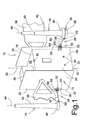
- Figure 1 is a partially broken perspective view, showing two omni-directional antennas oppositely mounted on a spacecraft structure with a method for improving their electric isolation in accordance with an embodiment of the present invention
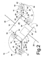
- Figure 2 is a partially broken top plan view of Fig. 1, illustrating the positions of the two antennas relative to the spacecraft structure in their deployed configuration, the respective antennas being illustrated in their stowed configuration in dashed lines.
- a spacecraft structure 10 which defines a generally elongated body 12 with a receive (Rx) antenna 14 and a transmit (Tx) antenna 16 mounted thereon.
- Both the Rx and Tx antennas 14, 16 are typically wide coverage antennas, most conventionally called global or earth coverage antennas. Any other type of antennas, such as omni-directional antennas or the like, could also be considered without departing from the scope of the present invention, as it would be obvious to one skilled in the art.
- the spacecraft structure body 12 defines generally opposed first and second longitudinal end walls 18, 20 and a body axis 22.
- the body 12 further defines a peripheral wall 24 generally extending between the first and second end walls 18, 20.
- the first end wall 18 is conventionally called the earth facing panel or deck of the spacecraft 10 and usually includes a few communication equipment, schematically represented by reference sign 26, mounted on its generally planar external surface 28.
- the second end wall 20 usually makes reference to the separation plane since the spacecraft 10 is generally secured to its launcher fairing (not shown) via that second end wall 20 and separates from the fairing shortly after launch.
- the peripheral wall 24 is generally divided into four wall sections referred to as the north 30, south 32, east 34 and west 36 panels.
- the north and south panels 30, 32 are usually radiator panels with solar panels 38 extending generally outwardly and perpendicularly therefrom, while the east and west panels 34, 36 supports the side mounted antennas 16, 14, respectively.
- Both the Rx and Tx antennas 14, 16 define a corresponding antenna base 40 from which a generally elongated antenna body 42 extends to have the antenna 14, 16 generally pointing in the direction of the Earth (not shown) to receive and transmit electro-magnetic signal thereto, respectively, such that their respective axis 44, 46 are generally parallel to the spacecraft axis 22.
- each antenna 14, 16 In order to improve the electric isolation of each antenna 14, 16 from any equipment 26 mounted on the earth facing panel 18 and more specifically from each other, they are mounted beside the structure body 12 on opposite sides thereof, with their base 40 being spaced apart from the earth facing panel 18 in a direction pointing generally inwardly from its external surface 28.
- the Rx and Tx antennas 14, 16 are mounted on the peripheral wall 24, at locations adjacent the separation plane 20 so as to limit the protrusion, or extension, of their respective antenna body 42 beyond the earth facing panel 18; the spacecraft body 12 acting as a screen or barrier for their electric isolation.
- the antennas 14, 16 are positioned relative to the earth facing panel 18 such that the antenna bodies 42 are as much as possible below the general level of the earth facing panel 18; preferably, at least between half (1 ⁇ 2) and three quarter (3 ⁇ 4) of the length of the antenna 14, 16 is located below the general level of the earth facing panel 18.
- the spacecraft body 12 and other major surrounding structures such as the solar panels 38 on the signal of the antennas 14, 16 are typically positioned in a spaced apart relationship relative to the spacecraft body 12 in a direction pointing outwardly from the external surface of the peripheral wall 24.
- each antenna 14, 16 is typically mounted on the spacecraft 10 using a relatively simple boom deployment mechanism 48 which allows the corresponding antenna 14, 16 to be displaced from a stowed or launch configuration in proximity to the spacecraft body 12, as shown in dashed lines in Fig. 2, to a deployed or flight configuration generally away from the spacecraft body 12, as shown in solid lines in Figs. 1 and 2.
- the stowed configuration allows to have full size rigid antennas 14, 16 directly mounted on the spacecraft 10 that fit into the spacecraft envelope inside the launcher fairing (not shown), thereby eliminating the need of having an additional deployment mechanism to further deploy the antenna itself.
- the boom deployment mechanism 48 similar for both Rx and Tx antennas 14, 16, includes a mounting or supporting boom 50, a hinge assembly 52 and a hold-down and release mechanism 54 (HRM).
- the boom 50 defines generally opposed first and second boom longitudinal ends 56, 58.
- the boom first end 56 is secured to the antenna base 40 and the boom second end 58 is pivotally mounted on the hinge assembly 52 about a mounting axis 53 generally parallel to the spacecraft axis 22.
- the hold-down and release mechanism 54 includes upper 60 and lower 62 brackets with corresponding pin pullers, separation nuts (not shown) or the like mechanisms used to retain the corresponding antenna 14, 16 in stowed configuration.
- the hinge assembly 52 includes a biasing means, such as a spring 64 or the like, biasing the antenna 14, 16 in the deployed configuration and an abutment means, or latching means (not shown), to maintain and/or lock the antenna 14, 16 in the deployed configuration.
- the pin pullers, separation nuts are usually activated by a releasing mechanism (not shown) to release the antenna 14, 16 from the stowed configuration, then the spring 64 biases the antenna 14, 16 in the deployed configuration. When in the deployed configuration, the antenna 14, 16 is locked in that position by the latching means.
- the boom 50 is in a generally parallel relationship relative to the corresponding spacecraft east 34 or west 36 panel with the boom second end 58 and the hinge assembly 52 generally adjacent an outer intersection 55, 57, or corner formed, between two adjacent panels 32, 34 and 30, 36 of the peripheral wall 24.
- the Rx and Tx antennas 14, 16 deploy from their stowed configuration to their deployed configuration by the deployment angle 66, 68, respectively.
- the predetermined deployment angles 66, 68 may be anywhere between substantially zero (0) and two hundred and seventy (270) degrees. More typically, the deployment angles are between substantially ninety (90) and one hundred and eighty (180) degrees, so as to be generally closer to the generally opposed corner 55, 57 than to either one of the two adjacent panels 32, 34 or 30, 36 forming the corner 55, 57.
- the scattering effect on the antenna beams is minimized with deployment angles 66, 68 being between substantially one hundred (100) and one hundred and thirty (130) degrees.
- deployment angles 66, 68 being between substantially one hundred (100) and one hundred and thirty (130) degrees.
- the two deployment angles 66, 68 are not necessarily identical, they are typically similar such that the two antennas 14, 16 are generally opposed from each other with the spacecraft body 12 there between. These positions significantly improve the electric isolation of the two antennas 14, 16, especially from one another; while reducing the risk of commonly known Passive Inter-Modulation (PIM) products affecting the Rx antenna 14.
- PIM Passive Inter-Modulation
- any type of structure on which antennas can be mounted such as a transmission tower, a building or the like with polyhedral or cylindrical shape could be similarly considered without departing from the scope of the present invention; such that the antennas are mounted on the side of the structure and set back relative to the first end wall 18 so as to be at least partially invisible or hidden there from.
- any type of deployment mechanism including any antenna deployment, could be considered without departing from the scope of the present invention, although some mass and design complexity are added to the antenna.
Landscapes
- Physics & Mathematics (AREA)
- Engineering & Computer Science (AREA)
- Astronomy & Astrophysics (AREA)
- General Physics & Mathematics (AREA)
- Remote Sensing (AREA)
- Aviation & Aerospace Engineering (AREA)
- Details Of Aerials (AREA)
- Support Of Aerials (AREA)
Applications Claiming Priority (2)
| Application Number | Priority Date | Filing Date | Title |
|---|---|---|---|
| US43662602P | 2002-12-30 | 2002-12-30 | |
| US436626P | 2002-12-30 |
Publications (2)
| Publication Number | Publication Date |
|---|---|
| EP1435676A1 true EP1435676A1 (de) | 2004-07-07 |
| EP1435676B1 EP1435676B1 (de) | 2006-12-13 |
Family
ID=32508049
Family Applications (1)
| Application Number | Title | Priority Date | Filing Date |
|---|---|---|---|
| EP03293345A Expired - Lifetime EP1435676B1 (de) | 2002-12-30 | 2003-12-29 | Verfahren zur Verbesserung der Entkopplung von einer auf einer Struktur montierten Antenne |
Country Status (4)
| Country | Link |
|---|---|
| US (1) | US7138959B2 (de) |
| EP (1) | EP1435676B1 (de) |
| AT (1) | ATE348413T1 (de) |
| DE (1) | DE60310359D1 (de) |
Cited By (2)
| Publication number | Priority date | Publication date | Assignee | Title |
|---|---|---|---|---|
| CN112949044A (zh) * | 2021-02-08 | 2021-06-11 | 北京京航计算通讯研究所 | 航天器天线安装位置和天线指向选取的确定方法 |
| CN113009512A (zh) * | 2021-02-08 | 2021-06-22 | 北京京航计算通讯研究所 | 航天器天线安装位置和天线指向选取的确定系统 |
Families Citing this family (7)
| Publication number | Priority date | Publication date | Assignee | Title |
|---|---|---|---|---|
| US20050176372A1 (en) * | 2004-02-05 | 2005-08-11 | Wheat International Communications Corporation | Highly integrated reliable architectural radio system for maritime application |
| US7348930B2 (en) * | 2005-01-21 | 2008-03-25 | Rotani, Inc. | Method and apparatus for a radio transceiver |
| CA2867303C (en) | 2006-02-28 | 2015-07-14 | Helvetia Ip Ag | Methods and apparatus for overlapping mimo antenna physical sectors |
| KR100772415B1 (ko) * | 2006-09-11 | 2007-11-01 | 삼성전자주식회사 | 안테나 |
| US9878806B2 (en) * | 2015-03-09 | 2018-01-30 | Space Systems/Loral, Llc | On-orbit assembly of communication satellites |
| US9979069B2 (en) | 2016-05-02 | 2018-05-22 | Motorola Solutions, Inc. | Wireless broadband/land mobile radio antenna system |
| CN107749512B (zh) * | 2017-11-20 | 2023-11-28 | 广东通宇通讯股份有限公司 | 天线底座及天线 |
Citations (4)
| Publication number | Priority date | Publication date | Assignee | Title |
|---|---|---|---|---|
| US4115784A (en) * | 1977-02-04 | 1978-09-19 | The United States Of America As Represented By The Secretary Of The Air Force | Deployable ground plane antenna |
| EP0692839A1 (de) * | 1994-07-11 | 1996-01-17 | DORNIER GmbH | Verstauen und Entfalten des Antennesystems eines Scatterometers auf einem Satelliten |
| US5966104A (en) * | 1998-03-31 | 1999-10-12 | Hughes Electronics Corporation | Antenna having movable reflectors |
| US6353419B1 (en) * | 1999-03-11 | 2002-03-05 | Lucent Technologies, Inc. | Antenna deployer for raised microcells |
Family Cites Families (5)
| Publication number | Priority date | Publication date | Assignee | Title |
|---|---|---|---|---|
| US5264862A (en) | 1991-12-10 | 1993-11-23 | Hazeltine Corp. | High-isolation collocated antenna systems |
| US5644320A (en) * | 1994-06-30 | 1997-07-01 | Compaq Computer Corporation | Antenna system for a notebook computer |
| US5764194A (en) * | 1995-12-22 | 1998-06-09 | Thomson Consumer Electronics, Inc. | Antenna orientation assembly |
| US6049315A (en) | 1997-07-01 | 2000-04-11 | Lucent Technologies, Inc. | Repeater isolation through antenna polarization diversity |
| US6917344B2 (en) * | 2002-04-12 | 2005-07-12 | Andrew Corporation | System for isolating an auxiliary antenna from a main antenna mounted in a common antenna assembly |
-
2003
- 2003-12-29 DE DE60310359T patent/DE60310359D1/de not_active Expired - Fee Related
- 2003-12-29 AT AT03293345T patent/ATE348413T1/de not_active IP Right Cessation
- 2003-12-29 EP EP03293345A patent/EP1435676B1/de not_active Expired - Lifetime
- 2003-12-30 US US10/747,278 patent/US7138959B2/en not_active Expired - Lifetime
Patent Citations (4)
| Publication number | Priority date | Publication date | Assignee | Title |
|---|---|---|---|---|
| US4115784A (en) * | 1977-02-04 | 1978-09-19 | The United States Of America As Represented By The Secretary Of The Air Force | Deployable ground plane antenna |
| EP0692839A1 (de) * | 1994-07-11 | 1996-01-17 | DORNIER GmbH | Verstauen und Entfalten des Antennesystems eines Scatterometers auf einem Satelliten |
| US5966104A (en) * | 1998-03-31 | 1999-10-12 | Hughes Electronics Corporation | Antenna having movable reflectors |
| US6353419B1 (en) * | 1999-03-11 | 2002-03-05 | Lucent Technologies, Inc. | Antenna deployer for raised microcells |
Cited By (3)
| Publication number | Priority date | Publication date | Assignee | Title |
|---|---|---|---|---|
| CN112949044A (zh) * | 2021-02-08 | 2021-06-11 | 北京京航计算通讯研究所 | 航天器天线安装位置和天线指向选取的确定方法 |
| CN113009512A (zh) * | 2021-02-08 | 2021-06-22 | 北京京航计算通讯研究所 | 航天器天线安装位置和天线指向选取的确定系统 |
| CN113009512B (zh) * | 2021-02-08 | 2022-11-22 | 北京京航计算通讯研究所 | 航天器天线安装位置和天线指向选取的确定系统 |
Also Published As
| Publication number | Publication date |
|---|---|
| ATE348413T1 (de) | 2007-01-15 |
| EP1435676B1 (de) | 2006-12-13 |
| US20040150580A1 (en) | 2004-08-05 |
| US7138959B2 (en) | 2006-11-21 |
| DE60310359D1 (de) | 2007-01-25 |
Similar Documents
| Publication | Publication Date | Title |
|---|---|---|
| EP3025392B1 (de) | Antenne mit polarisationsabhängigem elektromagnetischem bandabstand und zugehörige verfahren | |
| US11196184B2 (en) | Broadband antenna array | |
| US20150130673A1 (en) | Beam-Steered Wide Bandwidth Electromagnetic Band Gap Antenna | |
| US8130164B2 (en) | Broadband coplanar antenna element | |
| US7071879B2 (en) | Dielectric-resonator array antenna system | |
| EP3375044B1 (de) | Ebg-antenne mit gerichteter fixer strahlrampe | |
| EP2369677B1 (de) | Planare bidirektionale Strahlungsantenne | |
| JP6635566B1 (ja) | アンテナ | |
| JP2007501569A (ja) | 位相配列アンテナ吸収体及び関連方法 | |
| JP2019068423A (ja) | 凹部励起を有するフローティングダイポールアンテナ | |
| CN104937775A (zh) | 包括偶极振子元件和维瓦尔第元件的天线组件 | |
| US7138959B2 (en) | Method for improving isolation of an antenna mounted on a structure | |
| JP2006517074A (ja) | 移動電話送受器、pdaおよび他の電気的小型無線プラットフォームにおけるマルチアンテナダイバシティ | |
| JP6971163B2 (ja) | アンテナ装置 | |
| US12136767B2 (en) | Antenna assembly and base station antenna | |
| US11984673B2 (en) | Omni-directional MIMO antenna | |
| CN108539360B (zh) | 卫星用折叠型指向天线装置 | |
| US20220123475A1 (en) | Wireless communication device and antenna configuration method | |
| CN107959113B (zh) | 一种双线极化天线 | |
| Liu et al. | Printed yagi-uda antenna array on CubeSat | |
| Dweik et al. | A planar antenna array with integrated feed network for UAV applications | |
| US20130120207A1 (en) | Antenna module | |
| CN107978840B (zh) | 一种双线极化天线馈源阵列组件 | |
| US20240006771A1 (en) | Antenna assembly and base station antenna | |
| US20230261371A1 (en) | Unit cell antenna for phased arrays |
Legal Events
| Date | Code | Title | Description |
|---|---|---|---|
| PUAI | Public reference made under article 153(3) epc to a published international application that has entered the european phase |
Free format text: ORIGINAL CODE: 0009012 |
|
| AK | Designated contracting states |
Kind code of ref document: A1 Designated state(s): AT BE BG CH CY CZ DE DK EE ES FI FR GB GR HU IE IT LI LU MC NL PT RO SE SI SK TR |
|
| AX | Request for extension of the european patent |
Extension state: AL LT LV MK |
|
| 17P | Request for examination filed |
Effective date: 20041008 |
|
| 17Q | First examination report despatched |
Effective date: 20050202 |
|
| AKX | Designation fees paid |
Designated state(s): AT BE BG CH CY CZ DE DK EE ES FI FR GB GR HU IE IT LI LU MC NL PT RO SE SI SK TR |
|
| GRAP | Despatch of communication of intention to grant a patent |
Free format text: ORIGINAL CODE: EPIDOSNIGR1 |
|
| GRAS | Grant fee paid |
Free format text: ORIGINAL CODE: EPIDOSNIGR3 |
|
| GRAA | (expected) grant |
Free format text: ORIGINAL CODE: 0009210 |
|
| AK | Designated contracting states |
Kind code of ref document: B1 Designated state(s): AT BE BG CH CY CZ DE DK EE ES FI FR GB GR HU IE IT LI LU MC NL PT RO SE SI SK TR |
|
| PG25 | Lapsed in a contracting state [announced via postgrant information from national office to epo] |
Ref country code: FI Free format text: LAPSE BECAUSE OF FAILURE TO SUBMIT A TRANSLATION OF THE DESCRIPTION OR TO PAY THE FEE WITHIN THE PRESCRIBED TIME-LIMIT Effective date: 20061213 Ref country code: CH Free format text: LAPSE BECAUSE OF FAILURE TO SUBMIT A TRANSLATION OF THE DESCRIPTION OR TO PAY THE FEE WITHIN THE PRESCRIBED TIME-LIMIT Effective date: 20061213 Ref country code: IT Free format text: LAPSE BECAUSE OF FAILURE TO SUBMIT A TRANSLATION OF THE DESCRIPTION OR TO PAY THE FEE WITHIN THE PRESCRIBED TIME-LIMIT;WARNING: LAPSES OF ITALIAN PATENTS WITH EFFECTIVE DATE BEFORE 2007 MAY HAVE OCCURRED AT ANY TIME BEFORE 2007. THE CORRECT EFFECTIVE DATE MAY BE DIFFERENT FROM THE ONE RECORDED. Effective date: 20061213 Ref country code: LI Free format text: LAPSE BECAUSE OF FAILURE TO SUBMIT A TRANSLATION OF THE DESCRIPTION OR TO PAY THE FEE WITHIN THE PRESCRIBED TIME-LIMIT Effective date: 20061213 Ref country code: BE Free format text: LAPSE BECAUSE OF FAILURE TO SUBMIT A TRANSLATION OF THE DESCRIPTION OR TO PAY THE FEE WITHIN THE PRESCRIBED TIME-LIMIT Effective date: 20061213 Ref country code: SK Free format text: LAPSE BECAUSE OF FAILURE TO SUBMIT A TRANSLATION OF THE DESCRIPTION OR TO PAY THE FEE WITHIN THE PRESCRIBED TIME-LIMIT Effective date: 20061213 Ref country code: CZ Free format text: LAPSE BECAUSE OF FAILURE TO SUBMIT A TRANSLATION OF THE DESCRIPTION OR TO PAY THE FEE WITHIN THE PRESCRIBED TIME-LIMIT Effective date: 20061213 Ref country code: DK Free format text: LAPSE BECAUSE OF FAILURE TO SUBMIT A TRANSLATION OF THE DESCRIPTION OR TO PAY THE FEE WITHIN THE PRESCRIBED TIME-LIMIT Effective date: 20061213 Ref country code: AT Free format text: LAPSE BECAUSE OF FAILURE TO SUBMIT A TRANSLATION OF THE DESCRIPTION OR TO PAY THE FEE WITHIN THE PRESCRIBED TIME-LIMIT Effective date: 20061213 Ref country code: NL Free format text: LAPSE BECAUSE OF FAILURE TO SUBMIT A TRANSLATION OF THE DESCRIPTION OR TO PAY THE FEE WITHIN THE PRESCRIBED TIME-LIMIT Effective date: 20061213 Ref country code: RO Free format text: LAPSE BECAUSE OF FAILURE TO SUBMIT A TRANSLATION OF THE DESCRIPTION OR TO PAY THE FEE WITHIN THE PRESCRIBED TIME-LIMIT Effective date: 20061213 Ref country code: SI Free format text: LAPSE BECAUSE OF FAILURE TO SUBMIT A TRANSLATION OF THE DESCRIPTION OR TO PAY THE FEE WITHIN THE PRESCRIBED TIME-LIMIT Effective date: 20061213 |
|
| REG | Reference to a national code |
Ref country code: GB Ref legal event code: FG4D |
|
| PG25 | Lapsed in a contracting state [announced via postgrant information from national office to epo] |
Ref country code: IE Free format text: LAPSE BECAUSE OF NON-PAYMENT OF DUE FEES Effective date: 20061229 |
|
| REG | Reference to a national code |
Ref country code: CH Ref legal event code: EP |
|
| PG25 | Lapsed in a contracting state [announced via postgrant information from national office to epo] |
Ref country code: MC Free format text: LAPSE BECAUSE OF NON-PAYMENT OF DUE FEES Effective date: 20061231 |
|
| REG | Reference to a national code |
Ref country code: IE Ref legal event code: FG4D |
|
| REF | Corresponds to: |
Ref document number: 60310359 Country of ref document: DE Date of ref document: 20070125 Kind code of ref document: P |
|
| PG25 | Lapsed in a contracting state [announced via postgrant information from national office to epo] |
Ref country code: BG Free format text: LAPSE BECAUSE OF FAILURE TO SUBMIT A TRANSLATION OF THE DESCRIPTION OR TO PAY THE FEE WITHIN THE PRESCRIBED TIME-LIMIT Effective date: 20070313 Ref country code: SE Free format text: LAPSE BECAUSE OF FAILURE TO SUBMIT A TRANSLATION OF THE DESCRIPTION OR TO PAY THE FEE WITHIN THE PRESCRIBED TIME-LIMIT Effective date: 20070313 |
|
| PG25 | Lapsed in a contracting state [announced via postgrant information from national office to epo] |
Ref country code: ES Free format text: LAPSE BECAUSE OF FAILURE TO SUBMIT A TRANSLATION OF THE DESCRIPTION OR TO PAY THE FEE WITHIN THE PRESCRIBED TIME-LIMIT Effective date: 20070324 |
|
| REG | Reference to a national code |
Ref country code: GB Ref legal event code: 732E |
|
| RAP2 | Party data changed (patent owner data changed or rights of a patent transferred) |
Owner name: MACDONALD, DETTWILER AND ASSOCIATES CORPORATION |
|
| PG25 | Lapsed in a contracting state [announced via postgrant information from national office to epo] |
Ref country code: PT Free format text: LAPSE BECAUSE OF FAILURE TO SUBMIT A TRANSLATION OF THE DESCRIPTION OR TO PAY THE FEE WITHIN THE PRESCRIBED TIME-LIMIT Effective date: 20070514 |
|
| NLV1 | Nl: lapsed or annulled due to failure to fulfill the requirements of art. 29p and 29m of the patents act | ||
| REG | Reference to a national code |
Ref country code: CH Ref legal event code: PL |
|
| PG25 | Lapsed in a contracting state [announced via postgrant information from national office to epo] |
Ref country code: DE Free format text: LAPSE BECAUSE OF NON-PAYMENT OF DUE FEES Effective date: 20070703 |
|
| EN | Fr: translation not filed | ||
| ET | Fr: translation filed | ||
| REG | Reference to a national code |
Ref country code: FR Ref legal event code: EERR Free format text: CORRECTION DE BOPI 07/31 - BREVETS EUROPEENS DONT LA TRADUCTION N A PAS ETE REMISE A L INPI. IL Y A LIEU DE SUPPRIMER : LA MENTION DE LA NON REMISE. LA REMISE DE LA TRADUCTION EST PUBLIEE DANS LE PRESENT BOPI. |
|
| PLBE | No opposition filed within time limit |
Free format text: ORIGINAL CODE: 0009261 |
|
| STAA | Information on the status of an ep patent application or granted ep patent |
Free format text: STATUS: NO OPPOSITION FILED WITHIN TIME LIMIT |
|
| 26N | No opposition filed |
Effective date: 20070914 |
|
| REG | Reference to a national code |
Ref country code: FR Ref legal event code: ST Effective date: 20071030 |
|
| REG | Reference to a national code |
Ref country code: FR Ref legal event code: TP |
|
| REG | Reference to a national code |
Ref country code: FR Ref legal event code: RN |
|
| REG | Reference to a national code |
Ref country code: FR Ref legal event code: FC |
|
| PG25 | Lapsed in a contracting state [announced via postgrant information from national office to epo] |
Ref country code: GR Free format text: LAPSE BECAUSE OF FAILURE TO SUBMIT A TRANSLATION OF THE DESCRIPTION OR TO PAY THE FEE WITHIN THE PRESCRIBED TIME-LIMIT Effective date: 20070314 Ref country code: FR Free format text: LAPSE BECAUSE OF NON-PAYMENT OF DUE FEES Effective date: 20070102 |
|
| PG25 | Lapsed in a contracting state [announced via postgrant information from national office to epo] |
Ref country code: EE Free format text: LAPSE BECAUSE OF FAILURE TO SUBMIT A TRANSLATION OF THE DESCRIPTION OR TO PAY THE FEE WITHIN THE PRESCRIBED TIME-LIMIT Effective date: 20061213 |
|
| PG25 | Lapsed in a contracting state [announced via postgrant information from national office to epo] |
Ref country code: HU Free format text: LAPSE BECAUSE OF FAILURE TO SUBMIT A TRANSLATION OF THE DESCRIPTION OR TO PAY THE FEE WITHIN THE PRESCRIBED TIME-LIMIT Effective date: 20070614 Ref country code: TR Free format text: LAPSE BECAUSE OF FAILURE TO SUBMIT A TRANSLATION OF THE DESCRIPTION OR TO PAY THE FEE WITHIN THE PRESCRIBED TIME-LIMIT Effective date: 20061213 Ref country code: LU Free format text: LAPSE BECAUSE OF NON-PAYMENT OF DUE FEES Effective date: 20061229 |
|
| PG25 | Lapsed in a contracting state [announced via postgrant information from national office to epo] |
Ref country code: CY Free format text: LAPSE BECAUSE OF FAILURE TO SUBMIT A TRANSLATION OF THE DESCRIPTION OR TO PAY THE FEE WITHIN THE PRESCRIBED TIME-LIMIT Effective date: 20061213 |
|
| PGRI | Patent reinstated in contracting state [announced from national office to epo] |
Ref country code: FR Effective date: 20080206 |
|
| REG | Reference to a national code |
Ref country code: FR Ref legal event code: PLFP Year of fee payment: 13 |
|
| REG | Reference to a national code |
Ref country code: FR Ref legal event code: PLFP Year of fee payment: 14 |
|
| REG | Reference to a national code |
Ref country code: FR Ref legal event code: PLFP Year of fee payment: 15 |
|
| PGFP | Annual fee paid to national office [announced via postgrant information from national office to epo] |
Ref country code: FR Payment date: 20221215 Year of fee payment: 20 |
|
| PGFP | Annual fee paid to national office [announced via postgrant information from national office to epo] |
Ref country code: GB Payment date: 20230117 Year of fee payment: 20 |
|
| REG | Reference to a national code |
Ref country code: GB Ref legal event code: PE20 Expiry date: 20231228 |
|
| PG25 | Lapsed in a contracting state [announced via postgrant information from national office to epo] |
Ref country code: GB Free format text: LAPSE BECAUSE OF EXPIRATION OF PROTECTION Effective date: 20231228 |
|
| PG25 | Lapsed in a contracting state [announced via postgrant information from national office to epo] |
Ref country code: GB Free format text: LAPSE BECAUSE OF EXPIRATION OF PROTECTION Effective date: 20231228 |