EP1436107B1 - Herstellung von ausgangsmaterial zur verformung in halbfestem zustand - Google Patents
Herstellung von ausgangsmaterial zur verformung in halbfestem zustand Download PDFInfo
- Publication number
- EP1436107B1 EP1436107B1 EP02784094A EP02784094A EP1436107B1 EP 1436107 B1 EP1436107 B1 EP 1436107B1 EP 02784094 A EP02784094 A EP 02784094A EP 02784094 A EP02784094 A EP 02784094A EP 1436107 B1 EP1436107 B1 EP 1436107B1
- Authority
- EP
- European Patent Office
- Prior art keywords
- extruder
- raw material
- extrudate
- semi
- barrel
- Prior art date
- Legal status (The legal status is an assumption and is not a legal conclusion. Google has not performed a legal analysis and makes no representation as to the accuracy of the status listed.)
- Expired - Lifetime
Links
Images




Classifications
-
- B—PERFORMING OPERATIONS; TRANSPORTING
- B22—CASTING; POWDER METALLURGY
- B22F—WORKING METALLIC POWDER; MANUFACTURE OF ARTICLES FROM METALLIC POWDER; MAKING METALLIC POWDER; APPARATUS OR DEVICES SPECIALLY ADAPTED FOR METALLIC POWDER
- B22F8/00—Manufacture of articles from scrap or waste metal particles
-
- B—PERFORMING OPERATIONS; TRANSPORTING
- B22—CASTING; POWDER METALLURGY
- B22D—CASTING OF METALS; CASTING OF OTHER SUBSTANCES BY THE SAME PROCESSES OR DEVICES
- B22D17/00—Pressure die casting or injection die casting, i.e. casting in which the metal is forced into a mould under high pressure
- B22D17/007—Semi-solid pressure die casting
-
- B—PERFORMING OPERATIONS; TRANSPORTING
- B22—CASTING; POWDER METALLURGY
- B22F—WORKING METALLIC POWDER; MANUFACTURE OF ARTICLES FROM METALLIC POWDER; MAKING METALLIC POWDER; APPARATUS OR DEVICES SPECIALLY ADAPTED FOR METALLIC POWDER
- B22F3/00—Manufacture of workpieces or articles from metallic powder characterised by the manner of compacting or sintering; Apparatus specially adapted therefor ; Presses and furnaces
- B22F3/20—Manufacture of workpieces or articles from metallic powder characterised by the manner of compacting or sintering; Apparatus specially adapted therefor ; Presses and furnaces by extruding
-
- C—CHEMISTRY; METALLURGY
- C22—METALLURGY; FERROUS OR NON-FERROUS ALLOYS; TREATMENT OF ALLOYS OR NON-FERROUS METALS
- C22B—PRODUCTION AND REFINING OF METALS; PRETREATMENT OF RAW MATERIALS
- C22B1/00—Preliminary treatment of ores or scrap
- C22B1/005—Preliminary treatment of scrap
-
- C—CHEMISTRY; METALLURGY
- C22—METALLURGY; FERROUS OR NON-FERROUS ALLOYS; TREATMENT OF ALLOYS OR NON-FERROUS METALS
- C22B—PRODUCTION AND REFINING OF METALS; PRETREATMENT OF RAW MATERIALS
- C22B1/00—Preliminary treatment of ores or scrap
- C22B1/14—Agglomerating; Briquetting; Binding; Granulating
- C22B1/24—Binding; Briquetting ; Granulating
- C22B1/248—Binding; Briquetting ; Granulating of metal scrap or alloys
-
- C—CHEMISTRY; METALLURGY
- C22—METALLURGY; FERROUS OR NON-FERROUS ALLOYS; TREATMENT OF ALLOYS OR NON-FERROUS METALS
- C22B—PRODUCTION AND REFINING OF METALS; PRETREATMENT OF RAW MATERIALS
- C22B26/00—Obtaining alkali, alkaline earth metals or magnesium
- C22B26/20—Obtaining alkaline earth metals or magnesium
- C22B26/22—Obtaining magnesium
-
- C—CHEMISTRY; METALLURGY
- C22—METALLURGY; FERROUS OR NON-FERROUS ALLOYS; TREATMENT OF ALLOYS OR NON-FERROUS METALS
- C22C—ALLOYS
- C22C1/00—Making non-ferrous alloys
- C22C1/12—Making non-ferrous alloys by processing in a semi-solid state, e.g. holding the alloy in the solid-liquid phase
-
- B—PERFORMING OPERATIONS; TRANSPORTING
- B22—CASTING; POWDER METALLURGY
- B22F—WORKING METALLIC POWDER; MANUFACTURE OF ARTICLES FROM METALLIC POWDER; MAKING METALLIC POWDER; APPARATUS OR DEVICES SPECIALLY ADAPTED FOR METALLIC POWDER
- B22F2998/00—Supplementary information concerning processes or compositions relating to powder metallurgy
- B22F2998/10—Processes characterised by the sequence of their steps
-
- C—CHEMISTRY; METALLURGY
- C22—METALLURGY; FERROUS OR NON-FERROUS ALLOYS; TREATMENT OF ALLOYS OR NON-FERROUS METALS
- C22B—PRODUCTION AND REFINING OF METALS; PRETREATMENT OF RAW MATERIALS
- C22B1/00—Preliminary treatment of ores or scrap
- C22B1/14—Agglomerating; Briquetting; Binding; Granulating
- C22B1/16—Sintering; Agglomerating
- C22B1/20—Sintering; Agglomerating in sintering machines with movable grates
-
- Y—GENERAL TAGGING OF NEW TECHNOLOGICAL DEVELOPMENTS; GENERAL TAGGING OF CROSS-SECTIONAL TECHNOLOGIES SPANNING OVER SEVERAL SECTIONS OF THE IPC; TECHNICAL SUBJECTS COVERED BY FORMER USPC CROSS-REFERENCE ART COLLECTIONS [XRACs] AND DIGESTS
- Y02—TECHNOLOGIES OR APPLICATIONS FOR MITIGATION OR ADAPTATION AGAINST CLIMATE CHANGE
- Y02P—CLIMATE CHANGE MITIGATION TECHNOLOGIES IN THE PRODUCTION OR PROCESSING OF GOODS
- Y02P10/00—Technologies related to metal processing
- Y02P10/20—Recycling
-
- Y—GENERAL TAGGING OF NEW TECHNOLOGICAL DEVELOPMENTS; GENERAL TAGGING OF CROSS-SECTIONAL TECHNOLOGIES SPANNING OVER SEVERAL SECTIONS OF THE IPC; TECHNICAL SUBJECTS COVERED BY FORMER USPC CROSS-REFERENCE ART COLLECTIONS [XRACs] AND DIGESTS
- Y02—TECHNOLOGIES OR APPLICATIONS FOR MITIGATION OR ADAPTATION AGAINST CLIMATE CHANGE
- Y02W—CLIMATE CHANGE MITIGATION TECHNOLOGIES RELATED TO WASTEWATER TREATMENT OR WASTE MANAGEMENT
- Y02W30/00—Technologies for solid waste management
- Y02W30/50—Reuse, recycling or recovery technologies
Definitions
- the present invention relates to the production of feedstock materials for semi-solid forming, preferably feedstock materials comprising processed, reprocessed or materials to be recycled from semi-solid forming processes.
- Metal alloys for semi-solid forming are known in the art.
- the feedstock is produced by chipping bars comprising magnesium.
- the chips from these bars are, however, problematic because they are often contaminated with cutting fluid from the chipper and because they often contain metal contaminates from the knives of a chipper.
- These chips cause additional problems when used as feedstock because the size and shapes of the chips are non-uniform.
- voids form in injection molded parts because of non-uniform packing of the chips, (2) bridging may occur at the feed port, and/or (3) non-optimal performance of the injection molding apparatus occurs.
- One object of the present invention is to provide a process and apparatus for feedstock production that overcomes the problems and disadvantages of present feedstock materials.
- An additional object of the invention is to overcome obstacles and cost associated with the recycling of thixotropic revert due to irregular shape and potential for contamination.
- Another object of the invention is to produce a feedstock of a uniform shape which will feed well in subsequent processing.
- Yet another object of the invention is to provide a process and apparatus for removing volatile paints and oils from the recycled material used as raw material to provide the feedstock in a flashing step.
- Yet another object of the invention is to provide a process and apparatus for further alloying elements into spent alloys in the recycling and/or processing stage.
- Still another object of the invention is to provide an inexpensive means to reduce raw material, including ingots, to a uniform raw material for processing to feedstock without going through the traditional chipping process and with only minimal contamination from a size reduction process.
- a further object of the invention is to produce a feedstock having a microstructure that is favorable to thixoforming, which may include a globular structure or a crystalline microstructure.
- the process includes providing solid-state raw material, reducing the size of the raw material to produce particles of raw material of a size suitable for further processing, introducing the particles of raw material into an extruder and extruding particles of raw material to form an extrudate feedstock material. It may be desirable to separate the particles of raw material by size, weight, density or other physical characteristics before introducing the particles into the extruder.
- the extrudate feedstock desirably includes a non-dendritic microstructure such as a globular microstructure.
- an apparatus for producing feedstock materials for semi-solid metal forming according to claim 1.
- the apparatus includes an extruder, a feeder attached to and in communication with the extruder for introducing raw material into the extruder, and means for maintaining the raw material under an inert atmosphere in the feeder and as the raw material is fed into the extruder.
- the apparatus further includes a discharge orifice (e.g., die or nozzle) affixed to the extruder and through which the raw material exits the extruder as extrudate.
- the apparatus also includes a means for controlling the temperature of the extrudate while in the extruder and while the extrudate is being discharged from the extruder.
- the extrudate reaches a temperature sufficient to transform the raw material to its semi-solid state below its liquefying temperature.
- the apparatus includes a means for maintaining the extrudate under an inert atmosphere as the raw materials are being extruded into the extrudate, as the extrudate exits the discharge orifice and a pelletizer for dividing extrudate into pellets.
- Figure 1 depicts the process flow of raw material in accordance with an exemplary embodiment of the invention.
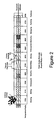
- Figure 2 depicts an extruder screw design in accordance with an exemplary embodiment of the invention.
- Figure 3 is a micrograph depicting a dendritic microstructure.
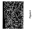
- Figure 4 is a micrograph depicting a globular microstructure.
- Figure 5 depicts a pelletizer in the form of a rotary knife apparatus in accordance with an exemplary embodiment of the invention.
- Figure 6 depicts a pelletizer in the form of a rotary cutter apparatus in accordance with an exemplary embodiment of the invention.
- Figure 7 depicts a pelletizer in the form of a non-mechanical pelletizer in accordance with an exemplary embodiment of the invention.
- Figure 8 is a micrograph of a cross-section of feedstock material of magnesium alloy produced in accordance with the present invention at 50X magnification.
- Figure 9 is a micrograph of a cross-section of feedstock material of magnesium alloy produced in accordance with the present invention at 100X magnification.
- Figure 10 is a micrograph of a cross-section of feedstock material of zinc alloy produced in accordance with the present invention at 140X magnification.
- the present invention provides a process to produce feedstock materials for semi-solid forming which have a preferred metallurgy, microstructure, and particle shape.
- Feedstock materials may comprise magnesium alloys such as AZ91 D, AM50, or AM60, and may also include currently non-thixomoldable magnesium alloys as well as currently non-thixomoldable non-magnesium alloys including, without limitation, zinc, aluminum, tin-lead and gallium based alloys.
- Raw materials for producing the feedstock material commonly are in a solid-state, and may include ingots, scrap from die casters or scrap, including scrap from thixomolders such as sprues or runners.
- the raw material may be contaminated with organic paints, coatings, oils, and other non-metal contaminates that typically volatilize at temperatures around 500°C.
- the raw material may comprise metal having a dendritic and/or a non-dendritic structure.
- at least some of the raw material may be recycled from previous thixoforming operations.
- a process for producing a feedstock material from raw materials includes subjecting the raw material to size reduction, mechanical separation and/or magnetic separation, microstructural and metallurgical refinement in a semi-solid state by extrusion and preferably pellet formation.
- raw materials in the form of scrap and/or virgin magnesium may be reduced in size by shredding raw materials in, for example, a shear shredding machine to provide particles of raw material.
- the particles may be of varying size and are generally no larger than the size of the feedthroat of the extruder, which is commonly no more than about 3" in size, and more commonly no greater than about 1" in size, and more desirably no greater than about 3/8" in size.
- the particles may also comprise more fine particles of about 1/4" or less in size.
- the size of the particles is dependant on the equipment used to further process the raw material to feedstock as would apparent to one skilled in the art.
- a shearing machine may be provided which is capable of reducing raw materials such as scrap, revert and ingots to a uniform, particle size that may be fed into an extruder.
- a shear shredding machine may, for example, have intermeshing rotary knives spaced apart by about 3/8" such that incoming raw material can be reduced to particles of about 3/8" or less in size.
- the raw material may be reduced by the size reduction apparatus to particles of about 1/4" in size or less.
- a different style of size reduction apparatus may include a different style of size reduction apparatus.
- two shearing sets may be arranged in series.
- a first set of blades e.g., rotary knives
- a second set of blades may reduce the particles produced by the first set of blades to particles of a second size (e.g., about 3/8" or less in size).
- raw materials may be reduced by a size reduction apparatus that includes two plates (preferably contoured plates) that can be drawn together to crush the raw materials to a desired size.
- the crushing apparatus may also include a heating system and an inert or protective atmosphere.
- the particles may be separated based upon physical characteristics of the particles. Common characteristics include size, weight, shape, density, magnetism, or other physical characteristic. Separation may be performed by one or more steps, as desired. For example, the particles may be reduced and separated by a predetermined size, such as about 3/8" or less. Separation may be employed with magnetized screens to remove magnetic contaminants, such as ferrous contaminants and prevent passage of particles greater than about 3/8". The magnetic contaminants may have entered during size reduction or have been a part of the raw materials. If magnetizing screens are used to remove magnetic contaminants, the screens are preferably interchangeable because they can be cleaned frequently and provide for maximum efficiency in removing magnetic contaminants.
- non-magnetic screens may be used in addition to magnetic screens. Regardless of whether a non-magnetic and/or a magnetic screen is employed, the screen also ensures that material of a predetermined size, such as about 3/8", or larger does not move into the next stage of the process.
- the size of material excluded from further processing by the screen depends, of course, on the mesh size of a given screen and may be varied as desired. The raw materials that do not pass through the screens may be recycled back to the size reduction apparatus and further reduced to proper particle size.
- raw material being introduced for processing may consist of highly variable shapes and have a wide variety of surface characteristics. These varied raw materials may include pieces that have open cavities, which may be susceptible to oxidation. The tendency of magnesium or other raw material to oxidize at high temperatures can be minimized by maintaining the raw materials in an inert atmosphere.
- gases that can be used to create the intert atmoshphere include the noble gases such as helium, argon and nitrogen, or other gases including SF 6 .
- the inert atmosphere may be provided by introducing a constant flow of inert gas, such as argon, on the raw material as it is introduced to the extruder.
- a plurality of rotating damper-like obstructions near the feed throat area may be used to provide the tumbling action. As the dampers rotate, the added material is forced to tumble and release any air bubbles contained therein.
- Another embodiment may require no moving parts, but rather may include a sequence of projections from the feed throat wall that also tumbles the raw material or particles that cause the release of air bubbles from the material.
- Extruders contemplated by the present invention may include, for example, twin-screw extruders, single screw extruders, and stationary screw extruders.
- Twin-screw extruders may be either co-rotating or counter-rotating extruders with either intermeshing or non-intermeshing screws.
- twin-screw extruder screws may be either identical or complementary.
- the extruder may be a co-rotating intermeshing twin-screw extruder with identical screws.
- a screw may be mounted in a given barrel such that the screw is capable of rotary movement relative to the barrel and is suitable for moving raw material along the barrel and eventually forces the extrudate through discharge orifice.
- Stationary screw extruders may also be used which includes a screw that does not rotate relative to a barrel.
- a plunger arranged behind the screw relative to the discharge orifice of the extruder may be employed to force material along the screw and, ultimately through the nozzle of the extruder.
- Screws and other components used in suitable extruders may optionally comprise a hardening and/or a non-corrosive coating on their outer surface. Due to the high corrosion potential of processing magnesium alloys in their semi-solid state, it is beneficial if extruder components that contact semi-solid magnesium are resistant to corrosion.
- extruder components may be manufactured from a cobalt based material such as, for example, STELLITE, a cobalt-chromium alloy, or lined with a corrosion resistant material such as, for example, SIALON, a silicon nitride alloy.
- suitable corrosion resistant materials include INCONEL, a nickel-chromium alloy, and HASTELLOY, a nickel-molybdenum alloy, although other corrosion resistant materials apparent to one skilled in the art may be used.
- Extruder screws may be designed in a modular fashion such that several elements line up on a shaft to produce screws of desired length.
- such elements may include, for example, high pitch forwarding elements, moderate pitch forwarding elements, low pitch forwarding elements, polygonal elements, distributive combers, kneading blocks, and blister rings.
- an aspect ratio of a screw may be between about 20:1 and 50:1.
- Extruder barrels may also be designed in a modular fashion wherein several segments fit together to make up the full extruder length. Barrel segments are typically manufactured in aspect ratios of 4:1, although other aspect ratios are also suitable depending on the bore diameter. Barrel segments may, optionally, be provided with independent thermal control thereby providing for a plurality of longitudinally spaced heating zones.
- thermal control includes control of cooling and/or heating capabilities. Cooling capabilities within the barrel may be provided by machined water or oil channels. Heating capabilities may include ceramic band heaters or induction heaters. Ceramic band heaters contemplated by the present invention are typically less expensive and easier to procure than induction heaters.
- a given barrel may comprise a plurality of heaters.
- Barrels may be manufactured such that the bulk metallurgy of a given barrel is one that would not react with the raw materials, for example semi-solid magnesium. This may be accomplished by providing a barrel lining.
- barrel linings that may resist corrosion include cobalt based metal or ceramic linings. Should a barrel lining be used, the lining and the barrel desirably are closely fitted to provide more efficient heat transfer to the barrel.
- barrel segments are normally bored with two intermeshing channels, resulting in a "figure 8" pattern.
- the barrel segments are bored through, with no other ports for materials to exit.
- the barrel segment may contain an opening for a vacuum port in order to assist in pulling off volatile components during extrusion.
- Such an arrangement is typically called a "flash zone”.
- all stages of the extruder for the incoming raw materials and additional alloying elements as well as the discharge orifice are in an inert atmosphere.
- the inert atmosphere may be created by the addition of an inert gas such as, for example, argon, to prevent oxidation of the semi-solid alloy.
- the alloy preferably is not exposed to ambient atmosphere until after the alloy cools to a temperature substantially below its solidus temperature.
- the apparatus for producing the feedstock is provided with means for maintaining the raw material under a cover gas in a feeder and as the raw material is fed into the extruder as particles.
- an inert atmosphere is provided with means to maintain the extrudate under an inert gas atmosphere as the extrudate exits the discharge orifice of the extruder.
- a hood arrangement may be used or, alternatively, a tubular ring comprising holes around its circumference may be used to direct streams of an inert gas onto the extrudate.
- An inert gas atmosphere may serve to protect the extrudate from oxidation and/or may cool the extrudate.
- the means for maintaining an inert gas atmosphere does not impede the flow of extrudate from the discharge orifice of the extruder.
- raw material may be introduced into the extruder at a rate less than or equal to 100% of the capacity of the extruder.
- the screw segments may be arranged along a shaft in a manner which promotes rapid acceptance of incoming raw material into the extruder near a feed throat and then compression of the raw material as it begins to heat and become more pliable.
- the incoming raw material may then be exposed to a series of kneading blocks arranged in a forwarding fashion so that dendrites present in the incoming raw material can be sheared and broken.
- An example of a dendritic microstructure is shown in Figure 3.
- the temperature of the extruder increases continually along this tortuous path to a point not above the liquidus temperature of the raw material.
- the alloy continues to travel forward through the extruder and to be mixed via moderate forwarding elements in the channel, it continues to increase in temperature due to frictional heating and/or heat from a ceramic band or induction heater. With sufficient shear and heating, the raw material eventually is transformed to a semi-solid extrudate, resulting in solids having a globular microstructure similar to that shown in Figure 4.
- the raw material may then be exposed to polygonal elements or high pitched forwarding elements within the extruder in a vacuum vented barrel segment, e.g. a "flash zone," where paints, oils, and other organic components become volatile and may be removed by a vacuum.
- This flash zone may be used alone or in conjunction with other flashing of the raw material, for example, before or after reduction of the raw material.
- a temperature profile along the length of a given extruder may be controlled such that the temperature increase from a feeder to a flash point, decrease after the flash point and then increases again in the direction of the discharge orifice as more clearly shown in Figure 2.
- the temperature profile along the length of a given barrel is maintained such that the temperature at a flash zone represents the maximum temperature in the profile.
- the temperature profile at the discharge orifice of the extruder represents the maximum temperature in the profile.
- Additional alloying elements can be added via an additional downstream feed throat.
- Suitable alloying materials will be apparent to one skilled in the art and may include, without limitation, manganese, zinc, silicon, aluminum, chromium, cobalt, lead, platinum, titanium or a combination thereof.
- the raw material and any additional alloying elements may be compressed and may pass through a series kneading blocks where the alloying elements are dispersed into the raw material.
- the resulting, newly formed alloy then may pass through a series of distributive combers where it is mixed more completely under sufficient shear and temperature to maintain a semi-solid extrudate.
- the alloy may be forwarded by high pitched forwarding elements, compressed by moderate pitched forwarding elements and fully compacted by low pitched forwarding elements which forward it to the discharge orifice. It is beneficial for the alloy to be compressed immediately before the discharge nozzle so that the extrudate is a continuous strand and/or so that oxygen cannot enter and oxidize the alloy.
- a rate of movement of the material through the extruder is substantially independent of a shearing rate of the material.
- extrusion particles of the raw material may, optionally, be introduced into a given extruder at a rate less than the maximum rate for that extruder.
- Suitable shear rates include rates of about 5 to 5000 reciprocal seconds, with a rate of about 500 to about 2000 being more preferable, and 1000 to 1500 reciprocal seconds being most preferred.
- a rate of movement of raw material along a barrel of a given extruder is substantially independent of the shearing rate of the raw material.
- Mean residence times of material in the extruder range from, for example, about 15 to about 200 seconds.
- an exemplary, non-limiting preferable rate of rotation for the screws is about 25 to 500 rpm, and more preferably about 50 to about 250 rpm, and even more preferably about 125 to about 175 rpm.
- Additional alloying elements may be added in order to resolve problems such as, for example, high iron content.
- manganese may be added as an alloying element because it can isolate iron in the microstructure and renew the corrosion resistance of magnesium if it has been lost due to ferrous contamination.
- Other alloying elements contemplated by the present invention include manganese, zinc, silicon, aluminum, chromium, cobalt, lead, platinum, and titanium.
- an additional alloying element may be added to the process while the element is at ambient temperature or at a temperature greater than an ambient temperature but less than a solidus temperature of a material in the extruder.
- the material must be kept sufficiently fluid to flow out of the orifice because there is no longer the capability to shear the alloy.
- One way to keep the material sufficiently fluid is through temperature control. For example, this may be accomplished by maintaining the temperature of the alloy in the discharge orifice at a temperature within plus or minus 5 degrees Kelvin of the intended discharge orifice temperature. The alloy may then be cooled quickly in the presence of an inert gas such as, for example, argon.
- a gear pump constructed of corrosion resistant components may be fitted to the discharge orifice to assist in pulling the solidifying magnesium from the extruder.
- a die including as many as ten ports or more through which material can exit may optionally be fitted to the discharge orifice.
- the extrudate exits the discharge orifice and/or die(s) generally in the form of a noodle-like strand or a plurality of noodle-like strands.
- a noodle-like strand typically comprises a circular cross section, which may have a diameter suitable for final application of the feedstock (e.g., about 1/4" or less for the preferred thixomolding operation). Depending on the final application in which the feedstock material may be employed, other cross sections may also be suitable.
- An apparatus according to the invention comprises means for controlling the temperature of the extrudate.
- the temperature may be controlled by, for example heating bands in the orifice, cooling fluid in the orifice, cooling gas emanating from a ring surrounding the orifice and/or the speed at which extrudate is pulled from or pushed out of the orifice.
- the extrudate while in noodle form, may be immediately exposed to cool argon gas to begin cooling and lock a preferred microstructure into place.
- Preferred microstructures may comprise, for example, a rosette structure, a globular structure and/or an encapsulated alpha phase which may be preferred in a given processing application because it flows more easily as compared to a dendritic structure if employed in the same processing application.
- a microstructure other than dendritic microstructure may also be preferred because of its physical properties, such as, for example greater tension strength and/or higher elongation as compared to dendritic materials.
- the high shear before discharge can also preferably eliminate the formation of dendrites upon cooling the extrudate.
- suitable shear rates just prior to entering the discharge orifice include, for example, shear rates of about 500 to about 2000 reciprocal seconds.
- Finite microstructures can be achieved by controlling the take-off and cooling rate from the extruder. The take off and/or cooling rates may be controlled by the speed of extruder screws or a plunger or by take-off via a gear pump. Take-off of the noodle may occur at speeds equal to or greater than the output of the extruder.
- the extrudate may be divided (most often by cutting) into a desired final size by a pelletizer.
- the extrudate exiting the extruder may be divided shortly after exiting or be transported by a conveyor under an inert gas atmosphere before being divided by the pelletizer.
- the pelletizer may be a mechanical cutter where the cutting action may be performed by a knife or blade as shown in Figure 5.
- cutting may be performed by a rotary cutter as shown in Figure 6.
- the cutting surface(s) may be made from the same material (e.g., same alloy) as the extrudate.
- a pelletizer may also be used to divide the extrudate into pellets via a non-mechanical cutter such as, for example, a laser or gas stream as shown in Figure 7.
- a high pressure argon stream can be used to cut the extrudate into pellets.
- Pellets are preferably of uniform size, having an aspect ratio of between 0.5:1 and 4.:1 and may, optionally, be cylindrical in shape. It should be noted that although rotary knives are suitable, they may potentially be a source of metal contaminants in the final product as the knives wear. Therefore, the use of like metals, a laser, or an inert gas is preferred for cutting.
- the pellets can be used as feedstock material for molding or other forming applications.
- the feedstock material may be made from most any combination of alloys as needed by a desired application.
- the feedstock desirably includes a microstructure other than the dendritic microstructure which can be controlled by the shear and temperature during the semi-solid extrusion process.
- magnesium alloy feedstock was prepared with the above identified process using a stationary screw extruder having sufficient shear to provide a globular microstructure as shown in Figures 8 and 9. The extruder maintained the raw material below the liquidus temperature but greater than the solidus temperature in a semi-solid state.
- zinc alloy feedstock having a much smaller semi-solid temperature range that magnesium alloys was also prepared with the above-identified process under shearing and temperature conditions suitable for formation of a globular microstructure as shown in Figure 10.
- Control over the temperature and forward plunger speed of the extruder was closely monitored. In the front barrel regions, a temperature tolerance range of only about 4 degrees Kelvin was allowed. The discharge orifice allowed for approximately a 10 degree Kelvin temperature range. The forward plunger speed was held between about 0.060" per second and about 0.120" per second to impart sufficient shear.
- Figure 1 depicts a flow diagram for one process for producing pelletized feedstock according to the present invention which has been described above.
- Figure 2 depicts a configuration for an extruder according to one embodiment of the present invention.
- the extruder has an aspect ratio of 40:1 and comprises a plurality of segments.
- a first feeding segment includes a feeding throat that is maintained at a temperature of about 533°K.
- a melting segment which is maintained at about 811°K
- a shearing segment which is maintained at about 869°K
- a devolatilizing vacuum flash segment which is maintained at about 872°K
- an alloying segment where alloying elements may be added which is maintained at about 869°K
- a disbursement segment which is maintained at about 869°K
- a distribution segment which is maintained at about 869°K
- a conveying segment which is maintained at about 869°K
- a pumping segment which is maintained at about 869°K
- a discharge segment which is maintained at about 872°K from which thixotropic extrudate may exit the extruder.
- Figure 3 shows a micrograph of a dendritic microstructure formed by solidification of an extrudate not sufficiently exposed to sufficient shear forces.
- Figure 4 shows a micrograph of globular microstructure resulting from solidification of an extrudate exposed to sufficient shear forces.
- Figure 5 depicts an exemplary rotary knife cutter according to one aspect of the invention.
- an extrudate strand or a plurality of extrudate strands intersect the blades from an axial direction.
- a rotary knife pelletizer would be best positioned at the discharge orifice or die of an extruder, although other positions, such as at the end of a conveyor, are also contemplated by the present invention.
- Figure 6 depicts a rotary cutter pelletizer according to another embodiment of the present invention.
- a rotary cutter When using a rotary cutter, an extrudate strand or a plurality of extrudate strands come into contact with the blades from a direction roughly perpendicular to an axis of rotation of the cutters.
- Rotary cutter extruders may preferably be used at a point downstream from the extruder, such as at the end of a conveyor, although rotary cutters may also be positioned at the discharge orifice of an extruder.
- Figure 7 depicts non-mechanical pelletizers that may be used to divide the extrudate of the present invention.
- the non-mechanical pelletizer may be in the form of a laser or fluid stream (e.g., gas or liquid stream).
- Figures 8, 9 and 10 are micrographs of various alloys that have been solidified after being exposed to sufficient shear and temperature to provide a globular microstructure.
Landscapes
- Engineering & Computer Science (AREA)
- Chemical & Material Sciences (AREA)
- Mechanical Engineering (AREA)
- Manufacturing & Machinery (AREA)
- Materials Engineering (AREA)
- Metallurgy (AREA)
- Organic Chemistry (AREA)
- Life Sciences & Earth Sciences (AREA)
- General Life Sciences & Earth Sciences (AREA)
- Geology (AREA)
- Environmental & Geological Engineering (AREA)
- Geochemistry & Mineralogy (AREA)
- Powder Metallurgy (AREA)
- Processing And Handling Of Plastics And Other Materials For Molding In General (AREA)
- Glass Compositions (AREA)
Claims (23)
- Vorrichtung zur Herstellung von Ausgangsmaterial für das Umformen von teilfestem-teilflüssigem Metall, gekennzeichnet durch- einen Extruder;- eine Zuführeinrichtung, welche an dem Extruder befestigt und durch welche dem Extruder Rohmaterial zuführbar ist;- Mittel, um das Rohmaterial in der Zuführeinrichtung und während der Zuführung zum Extruder unter einer Inertgasatmosphäre zu halten;- eine Austrittsöffnung, welche am Extruder befestigt ist und durch welche das Rohmaterial aus dem Extruder als Extrudat austritt, wobei das Extrudat eine Temperatur unterhalb der Liquidustemperatur des Rohmaterials, jedoch oberhalb der Solidustemperatur aufweist;- Mittel zur Regelung einer Temperatur des Rohmaterials innerhalb des Extruders und des Extrudats auf einer Temperatur unterhalb der Liquidustemperatur;- Mittel zum Halten des Extrudats unter einer Inertgasatmosphäre, während das Extrudat aus der Austrittsöffnung austritt; und- eine Granuliereinrichtung zur Zerteilung des Extrudats.
- Vorrichtung nach Anspruch 1, dadurch gekennzeichnet, dass der Extruder einen Zylinder aufweist, welcher eine Vielzahl von in Längsrichtung beabstandeten Heizzonen und eine Gasabzugszone aufweist.
- Vorrichtung nach Anspruch 1, dadurch gekennzeichnet, dass der Extruder mindestens eine Heizeinrichtung aufweist.
- Vorrichtung nach Anspruch 3, dadurch gekennzeichnet, dass die Heizeinrichtung als keramische Ringheizung oder Induktionsheizung ausgebildet ist.
- Vorrichtung nach Anspruch 1, dadurch gekennzeichnet, dass der Extruder eine einzelne, stationäre Schnecke aufweist, welche in dem Zylinder angeordnet ist.
- Vorrichtung nach Anspruch 5, dadurch gekennzeichnet, dass der Exruder einen Kolben zur Pressung des Rohmaterials durch den Extruder entlang der stationären Schnecke aufweist.
- Vorrichtung nach Anspruch 1, dadurch gekennzeichnet, dass der Extruder mindestens eine Schnecke aufweist, welche drehbar in Bezug auf den Zylinder und durch welche das Rohmaterial entlang des Zylinders in einer Richtung von der Zuführeinrichtung bis zur Austrittsöffnung förderbar ist.
- Vorrichtung nach Anspruch 1, dadurch gekennzeichnet, dass der Extruder einen Zylinder aufweist, welcher mit einer korrosionsbeständigen Auskleidung versehen ist.
- Vorrichtung nach Anspruch 1, dadurch gekennzeichnet, dass der Extruder mindestens eine Schnecke aufweist, welche auf ihrer äußeren Oberfläche ein härtbares Material aufweist.
- Vorrichtung nach Anspruch 1, dadurch gekennzeichnet, dass an der Austrittsöffnung des Extruders eine Zahnradpumpe angeordnet ist, durch welche die Entfernung des Extrudats unterstützt wird.
- Vorrichtung nach Anspruch 1, dadurch gekennzeichnet, dass Mittel zum Abtransport von aus der Austrittsöffnung austretendem Extrudat, vorzugsweise unter einer Inertgasatmosphäre vorgesehen sind.
- Vorrichtung nach Anspruch 1, dadurch gekennzeichnet, dass Mittel zur Aufrechterhaltung einer Inertgasatmosphäre für alle Stufen des Extruders - ausgenommen eine unter Unterdruck stehende Stufe, sofern vorhanden - vorgesehen sind.
- Vorrichtung nach Anspruch 1, dadurch gekennzeichnet, dass die Granuliereinrichtung mechanische Schneidwerkzeuge mit Klingen, herstellbar aus einer kompatiblen Legierung, aufweist.
- Vorrichtung nach Anspruch 1, dadurch gekennzeichnet, dass die Granuliereinrichtung eine nicht mechanische Schneideinrichtung aufweist.
- Vorrichtung nach Anspruch 1, dadurch gekennzeichnet, dass der Extruder eine Schnecke mit einem modularen Aufbau aufweist, wobei eine Vielzahl von Elementen entlang einer Welle zur Herstellung einer Schnecke vorbestimmter Länge positionierbar sind.
- Vorrichtung nach Anspruch 15, dadurch gekennzeichnet, dass die einzelnen Elemente mindestens ein Förderelement mit hoher Steigung, ein Förderelement mit mittlerer Steigung, ein Förderelement mit geringer Steigung, ein Polygonelement, ein Verteilerelement, einen Knetblock oder einen Blasenring aufweisen.
- Vorrichtung nach Anspruch 1, dadurch gekennzeichnet, dass zusätzlich eine Vorrichtung zur Reduzierung der Größe des Rohmaterials (Größenreduziervorrichtung) vorgesehen ist.
- Verfahren zur Herstellung von Ausgangsmaterial für das Umformen von teilfestem-teilflüssigem Metall, durchführbar mit einer Vorrichtung gemäß Anspruch 1, gekennzeichnet durch folgende Verfahrensschritte:- Bereitstellung von Rohmaterial in festem Zustand;- Reduzieren der Größe des Rohmaterials zur Herstellung von Partikeln aus Rohmaterial mit einer für das weitere Verfahren geeigneten Größe;- Einführen der Partikel aus Rohmaterial in den Extruder und- Extrudieren der Partikel aus Rohmaterial zur Erzeugung eines extrudierten Ausgangsmaterials, welches einen teilfesten-teilflüssigen Zustand aufweist.
- Verfahren nach Anspruch 18, dadurch gekennzeichnet, dass magnetische Fremdsubstanzen aus den Rohmaterialpartikein entfernt werden.
- Verfahren nach Anspruch 18, dadurch gekennzeichnet, dass während des Extrudiervorganges elementares Metall oder eine Legierung dem Rohmaterial zur Beeinflussung der metallurgischen Eigenschaften des Rohmaterials und/oder des Extrudats zugesetzt werden.
- Verfahren nach Anspruch 18, dadurch gekennzeichnet, dass das Rohmaterial mit einer Vorschubrate entlang des Zylinders extrudiert wird, welche im Wesentlichen unabhängig von der Scherrate des Rohmaterials ist.
- Verfahren nach Anspruch 18, dadurch gekennzeichnet, dass das Extrudat unter einer Inertgasatmosphäre gekühlt wird.
- Verfahren nach Anspruch 18, dadurch gekennzeichnet, dass das zugeführte Rohmaterial während des Extrudiervorganges mit einer Reihe von Knetblöcken in Kontakt gebracht wird, welche in einer die Förderwirkung unterstützenden Weise und zur Erzielung einer hinreichenden Scherwirkung angeordnet sind, sodass wenigstens ein Teil der in dem zugeführten Material enthaltenen dendritischen Strukturen beseitigt wird.
Applications Claiming Priority (3)
| Application Number | Priority Date | Filing Date | Title |
|---|---|---|---|
| US32933801P | 2001-10-16 | 2001-10-16 | |
| US329338P | 2001-10-16 | ||
| PCT/US2002/032721 WO2003033193A2 (en) | 2001-10-16 | 2002-10-15 | Feedstock materials for semi-solid forming |
Publications (2)
| Publication Number | Publication Date |
|---|---|
| EP1436107A2 EP1436107A2 (de) | 2004-07-14 |
| EP1436107B1 true EP1436107B1 (de) | 2006-03-22 |
Family
ID=23284915
Family Applications (1)
| Application Number | Title | Priority Date | Filing Date |
|---|---|---|---|
| EP02784094A Expired - Lifetime EP1436107B1 (de) | 2001-10-16 | 2002-10-15 | Herstellung von ausgangsmaterial zur verformung in halbfestem zustand |
Country Status (5)
| Country | Link |
|---|---|
| US (1) | US20060070419A1 (de) |
| EP (1) | EP1436107B1 (de) |
| AT (1) | ATE320874T1 (de) |
| DE (1) | DE60210126T2 (de) |
| WO (1) | WO2003033193A2 (de) |
Families Citing this family (3)
| Publication number | Priority date | Publication date | Assignee | Title |
|---|---|---|---|---|
| DE102010005353B4 (de) * | 2010-01-21 | 2015-12-31 | Thyssenkrupp Industrial Solutions Ag | Verfahren zur Herstellung von kokskammergerechten Einzelkompaktaten durch nichtmechanisches Teilen eines Kohlepresskuchens |
| DE102015219032A1 (de) * | 2015-10-01 | 2017-04-06 | Coperion Gmbh | Verfahren und Vorrichtung zur Herstellung einer Mischung aus einem metallischen Matrixmaterial und einem Zusatzstoff |
| CN109865812B (zh) * | 2019-03-29 | 2020-10-27 | 东北大学 | 一种金属流变净化压力成形设备 |
Citations (2)
| Publication number | Priority date | Publication date | Assignee | Title |
|---|---|---|---|---|
| EP0080787A2 (de) * | 1981-12-01 | 1983-06-08 | The Dow Chemical Company | Verfahren zum Herstellen einer metallischen Flüssig-Fest-Mischung |
| WO1994006586A1 (en) * | 1992-09-11 | 1994-03-31 | Comalco Aluminium Limited | Particulate feedstock for metal injection molding |
Family Cites Families (18)
| Publication number | Priority date | Publication date | Assignee | Title |
|---|---|---|---|---|
| US4694881A (en) * | 1981-12-01 | 1987-09-22 | The Dow Chemical Company | Method for making thixotropic materials |
| US5040589A (en) * | 1989-02-10 | 1991-08-20 | The Dow Chemical Company | Method and apparatus for the injection molding of metal alloys |
| US5577546A (en) * | 1992-09-11 | 1996-11-26 | Comalco Aluminium Limited | Particulate feedstock for metal injection molding |
| US5501266A (en) * | 1994-06-14 | 1996-03-26 | Cornell Research Foundation, Inc. | Method and apparatus for injection molding of semi-solid metals |
| US6068043A (en) * | 1995-12-26 | 2000-05-30 | Hot Metal Technologies, Inc. | Method and apparatus for nucleated forming of semi-solid metallic alloys from molten metals |
| US5711366A (en) * | 1996-05-31 | 1998-01-27 | Thixomat, Inc. | Apparatus for processing corrosive molten metals |
| US5680894A (en) * | 1996-10-23 | 1997-10-28 | Lindberg Corporation | Apparatus for the injection molding of a metal alloy: sub-ring concept |
| US5996679A (en) * | 1996-11-04 | 1999-12-07 | Thixomat, Inc. | Apparatus for semi-solid processing of a metal |
| US5983978A (en) * | 1997-09-30 | 1999-11-16 | Thixomat, Inc. | Thermal shock resistant apparatus for molding thixotropic materials |
| US6079477A (en) * | 1998-01-26 | 2000-06-27 | Amcan Castings Limited | Semi-solid metal forming process |
| US6135196A (en) * | 1998-03-31 | 2000-10-24 | Takata Corporation | Method and apparatus for manufacturing metallic parts by injection molding from the semi-solid state |
| US6120625A (en) * | 1998-06-10 | 2000-09-19 | Zhou; Youdong | Processes for producing fine grained metal compositions using continuous extrusion for semi-solid forming of shaped articles |
| US6162377A (en) * | 1999-02-23 | 2000-12-19 | Alberta Research Council Inc. | Apparatus and method for the formation of uniform spherical particles |
| US6461403B1 (en) * | 1999-02-23 | 2002-10-08 | Alberta Research Council Inc. | Apparatus and method for the formation of uniform spherical particles |
| US6299665B1 (en) * | 1999-07-06 | 2001-10-09 | Thixomat, Inc. | Activated feedstock |
| US20020170696A1 (en) * | 2001-05-18 | 2002-11-21 | Ron Akers | Apparatus for molding metals |
| US6736188B2 (en) * | 2002-06-28 | 2004-05-18 | Thixomat, Inc. | Apparatus for molding molten materials |
| US20060196626A1 (en) * | 2005-03-07 | 2006-09-07 | Thixomat, Inc. | Semisolid metal injection molding machine components |
-
2002
- 2002-10-15 WO PCT/US2002/032721 patent/WO2003033193A2/en not_active Ceased
- 2002-10-15 EP EP02784094A patent/EP1436107B1/de not_active Expired - Lifetime
- 2002-10-15 DE DE2002610126 patent/DE60210126T2/de not_active Expired - Fee Related
- 2002-10-15 US US10/492,602 patent/US20060070419A1/en not_active Abandoned
- 2002-10-15 AT AT02784094T patent/ATE320874T1/de not_active IP Right Cessation
Patent Citations (2)
| Publication number | Priority date | Publication date | Assignee | Title |
|---|---|---|---|---|
| EP0080787A2 (de) * | 1981-12-01 | 1983-06-08 | The Dow Chemical Company | Verfahren zum Herstellen einer metallischen Flüssig-Fest-Mischung |
| WO1994006586A1 (en) * | 1992-09-11 | 1994-03-31 | Comalco Aluminium Limited | Particulate feedstock for metal injection molding |
Also Published As
| Publication number | Publication date |
|---|---|
| WO2003033193A2 (en) | 2003-04-24 |
| ATE320874T1 (de) | 2006-04-15 |
| DE60210126D1 (de) | 2006-05-11 |
| WO2003033193A3 (en) | 2004-03-11 |
| DE60210126T2 (de) | 2006-08-31 |
| EP1436107A2 (de) | 2004-07-14 |
| US20060070419A1 (en) | 2006-04-06 |
Similar Documents
| Publication | Publication Date | Title |
|---|---|---|
| EP0080786B1 (de) | Verfahren zum Herstellen einer metallischen Flüssig-Fest-Mischung | |
| EP0080787B1 (de) | Verfahren zum Herstellen einer metallischen Flüssig-Fest-Mischung | |
| EP1971698B1 (de) | Verfahren zur herstellung eines verbundwerkstoffs oder eines vorläuferprodukts zur herstellung eines verbundwerkstoffs | |
| JP2003509221A (ja) | 半流動金属スラリー及び成形材の製造方法及び装置 | |
| US5413644A (en) | Beryllium-containing alloys of magnesium | |
| EP2421997B1 (de) | Herstellung von rundlichen metallpartikeln | |
| CN1446134A (zh) | 制造金属合金铸件的方法和设备 | |
| US6120625A (en) | Processes for producing fine grained metal compositions using continuous extrusion for semi-solid forming of shaped articles | |
| US6350328B1 (en) | Metal injection molding | |
| US20060070419A1 (en) | Feedstock materials for semi-solid forming | |
| WO2001002612A1 (en) | Activated feedstock | |
| KR100442155B1 (ko) | 마그네슘 합금부재용 재료 및 마그네슘 합금부재의 제조방법 | |
| JP3220072B2 (ja) | 金属射出成形用ペレットの製造方法 | |
| JPH06256809A (ja) | 金属加工屑の再生方法 | |
| JP3814219B2 (ja) | 射出成形品の成形方法 | |
| DE10005122A1 (de) | Verfahren und Extruder zur Thixoextrusion von Leichtmetallen | |
| NZ615063A (en) | Extrusion of high temperature formable non-ferrous metals | |
| NZ615063B2 (en) | Extrusion of high temperature formable non-ferrous metals |
Legal Events
| Date | Code | Title | Description |
|---|---|---|---|
| PUAI | Public reference made under article 153(3) epc to a published international application that has entered the european phase |
Free format text: ORIGINAL CODE: 0009012 |
|
| 17P | Request for examination filed |
Effective date: 20040505 |
|
| AK | Designated contracting states |
Kind code of ref document: A2 Designated state(s): AT BE BG CH CY CZ DE DK EE ES FI FR GB GR IE IT LI LU MC NL PT SE SK TR |
|
| AX | Request for extension of the european patent |
Extension state: AL LT LV MK RO SI |
|
| 17Q | First examination report despatched |
Effective date: 20050401 |
|
| GRAP | Despatch of communication of intention to grant a patent |
Free format text: ORIGINAL CODE: EPIDOSNIGR1 |
|
| RTI1 | Title (correction) |
Free format text: PRODUCTION OF FEEDSTOCK MATERIALS FOR SEMI-SOLID FORMING |
|
| GRAS | Grant fee paid |
Free format text: ORIGINAL CODE: EPIDOSNIGR3 |
|
| GRAA | (expected) grant |
Free format text: ORIGINAL CODE: 0009210 |
|
| AK | Designated contracting states |
Kind code of ref document: B1 Designated state(s): AT BE BG CH CY CZ DE DK EE ES FI FR GB GR IE IT LI LU MC NL PT SE SK TR |
|
| PG25 | Lapsed in a contracting state [announced via postgrant information from national office to epo] |
Ref country code: IT Free format text: LAPSE BECAUSE OF FAILURE TO SUBMIT A TRANSLATION OF THE DESCRIPTION OR TO PAY THE FEE WITHIN THE PRESCRIBED TIME-LIMIT;WARNING: LAPSES OF ITALIAN PATENTS WITH EFFECTIVE DATE BEFORE 2007 MAY HAVE OCCURRED AT ANY TIME BEFORE 2007. THE CORRECT EFFECTIVE DATE MAY BE DIFFERENT FROM THE ONE RECORDED. Effective date: 20060322 Ref country code: AT Free format text: LAPSE BECAUSE OF FAILURE TO SUBMIT A TRANSLATION OF THE DESCRIPTION OR TO PAY THE FEE WITHIN THE PRESCRIBED TIME-LIMIT Effective date: 20060322 Ref country code: SK Free format text: LAPSE BECAUSE OF FAILURE TO SUBMIT A TRANSLATION OF THE DESCRIPTION OR TO PAY THE FEE WITHIN THE PRESCRIBED TIME-LIMIT Effective date: 20060322 Ref country code: NL Free format text: LAPSE BECAUSE OF FAILURE TO SUBMIT A TRANSLATION OF THE DESCRIPTION OR TO PAY THE FEE WITHIN THE PRESCRIBED TIME-LIMIT Effective date: 20060322 Ref country code: BE Free format text: LAPSE BECAUSE OF FAILURE TO SUBMIT A TRANSLATION OF THE DESCRIPTION OR TO PAY THE FEE WITHIN THE PRESCRIBED TIME-LIMIT Effective date: 20060322 |
|
| REG | Reference to a national code |
Ref country code: GB Ref legal event code: FG4D |
|
| RIN1 | Information on inventor provided before grant (corrected) |
Inventor name: KRAMSCHUSTER, ADAM Inventor name: WANG, NAN Inventor name: JOHNSON, KRISTY Inventor name: SCHOUSEK, BRIAN, WALTER Inventor name: POHL, STEPHEN Inventor name: BJORK, TODD |
|
| REG | Reference to a national code |
Ref country code: CH Ref legal event code: EP |
|
| REG | Reference to a national code |
Ref country code: IE Ref legal event code: FG4D |
|
| REF | Corresponds to: |
Ref document number: 60210126 Country of ref document: DE Date of ref document: 20060511 Kind code of ref document: P |
|
| PG25 | Lapsed in a contracting state [announced via postgrant information from national office to epo] |
Ref country code: SE Free format text: LAPSE BECAUSE OF FAILURE TO SUBMIT A TRANSLATION OF THE DESCRIPTION OR TO PAY THE FEE WITHIN THE PRESCRIBED TIME-LIMIT Effective date: 20060622 Ref country code: BG Free format text: LAPSE BECAUSE OF FAILURE TO SUBMIT A TRANSLATION OF THE DESCRIPTION OR TO PAY THE FEE WITHIN THE PRESCRIBED TIME-LIMIT Effective date: 20060622 Ref country code: DK Free format text: LAPSE BECAUSE OF FAILURE TO SUBMIT A TRANSLATION OF THE DESCRIPTION OR TO PAY THE FEE WITHIN THE PRESCRIBED TIME-LIMIT Effective date: 20060622 |
|
| PG25 | Lapsed in a contracting state [announced via postgrant information from national office to epo] |
Ref country code: ES Free format text: LAPSE BECAUSE OF FAILURE TO SUBMIT A TRANSLATION OF THE DESCRIPTION OR TO PAY THE FEE WITHIN THE PRESCRIBED TIME-LIMIT Effective date: 20060703 |
|
| REG | Reference to a national code |
Ref country code: CH Ref legal event code: NV Representative=s name: ISLER & ISLER |
|
| PG25 | Lapsed in a contracting state [announced via postgrant information from national office to epo] |
Ref country code: PT Free format text: LAPSE BECAUSE OF FAILURE TO SUBMIT A TRANSLATION OF THE DESCRIPTION OR TO PAY THE FEE WITHIN THE PRESCRIBED TIME-LIMIT Effective date: 20060822 |
|
| NLV1 | Nl: lapsed or annulled due to failure to fulfill the requirements of art. 29p and 29m of the patents act | ||
| PG25 | Lapsed in a contracting state [announced via postgrant information from national office to epo] |
Ref country code: IE Free format text: LAPSE BECAUSE OF NON-PAYMENT OF DUE FEES Effective date: 20061016 |
|
| ET | Fr: translation filed | ||
| PG25 | Lapsed in a contracting state [announced via postgrant information from national office to epo] |
Ref country code: MC Free format text: LAPSE BECAUSE OF NON-PAYMENT OF DUE FEES Effective date: 20061031 |
|
| PLBE | No opposition filed within time limit |
Free format text: ORIGINAL CODE: 0009261 |
|
| STAA | Information on the status of an ep patent application or granted ep patent |
Free format text: STATUS: NO OPPOSITION FILED WITHIN TIME LIMIT |
|
| 26N | No opposition filed |
Effective date: 20061227 |
|
| PG25 | Lapsed in a contracting state [announced via postgrant information from national office to epo] |
Ref country code: GR Free format text: LAPSE BECAUSE OF FAILURE TO SUBMIT A TRANSLATION OF THE DESCRIPTION OR TO PAY THE FEE WITHIN THE PRESCRIBED TIME-LIMIT Effective date: 20060623 Ref country code: CZ Free format text: LAPSE BECAUSE OF FAILURE TO SUBMIT A TRANSLATION OF THE DESCRIPTION OR TO PAY THE FEE WITHIN THE PRESCRIBED TIME-LIMIT Effective date: 20060322 |
|
| PG25 | Lapsed in a contracting state [announced via postgrant information from national office to epo] |
Ref country code: FI Free format text: LAPSE BECAUSE OF FAILURE TO SUBMIT A TRANSLATION OF THE DESCRIPTION OR TO PAY THE FEE WITHIN THE PRESCRIBED TIME-LIMIT Effective date: 20060322 Ref country code: EE Free format text: LAPSE BECAUSE OF FAILURE TO SUBMIT A TRANSLATION OF THE DESCRIPTION OR TO PAY THE FEE WITHIN THE PRESCRIBED TIME-LIMIT Effective date: 20060322 |
|
| PG25 | Lapsed in a contracting state [announced via postgrant information from national office to epo] |
Ref country code: LU Free format text: LAPSE BECAUSE OF NON-PAYMENT OF DUE FEES Effective date: 20061015 Ref country code: TR Free format text: LAPSE BECAUSE OF FAILURE TO SUBMIT A TRANSLATION OF THE DESCRIPTION OR TO PAY THE FEE WITHIN THE PRESCRIBED TIME-LIMIT Effective date: 20060322 |
|
| PG25 | Lapsed in a contracting state [announced via postgrant information from national office to epo] |
Ref country code: CY Free format text: LAPSE BECAUSE OF FAILURE TO SUBMIT A TRANSLATION OF THE DESCRIPTION OR TO PAY THE FEE WITHIN THE PRESCRIBED TIME-LIMIT Effective date: 20060322 |
|
| PGFP | Annual fee paid to national office [announced via postgrant information from national office to epo] |
Ref country code: CH Payment date: 20081015 Year of fee payment: 7 Ref country code: DE Payment date: 20081022 Year of fee payment: 7 |
|
| PGFP | Annual fee paid to national office [announced via postgrant information from national office to epo] |
Ref country code: FR Payment date: 20081014 Year of fee payment: 7 |
|
| PGFP | Annual fee paid to national office [announced via postgrant information from national office to epo] |
Ref country code: GB Payment date: 20081021 Year of fee payment: 7 |
|
| REG | Reference to a national code |
Ref country code: CH Ref legal event code: PL |
|
| REG | Reference to a national code |
Ref country code: FR Ref legal event code: ST Effective date: 20100630 |
|
| PG25 | Lapsed in a contracting state [announced via postgrant information from national office to epo] |
Ref country code: FR Free format text: LAPSE BECAUSE OF NON-PAYMENT OF DUE FEES Effective date: 20091102 Ref country code: DE Free format text: LAPSE BECAUSE OF NON-PAYMENT OF DUE FEES Effective date: 20100501 |
|
| PG25 | Lapsed in a contracting state [announced via postgrant information from national office to epo] |
Ref country code: CH Free format text: LAPSE BECAUSE OF NON-PAYMENT OF DUE FEES Effective date: 20091031 Ref country code: LI Free format text: LAPSE BECAUSE OF NON-PAYMENT OF DUE FEES Effective date: 20091031 |
|
| PG25 | Lapsed in a contracting state [announced via postgrant information from national office to epo] |
Ref country code: GB Free format text: LAPSE BECAUSE OF NON-PAYMENT OF DUE FEES Effective date: 20091015 |