EP1436441B1 - Procede d'application de revetements d'alliages metalliques et composant revêtu - Google Patents
Procede d'application de revetements d'alliages metalliques et composant revêtu Download PDFInfo
- Publication number
- EP1436441B1 EP1436441B1 EP02800327A EP02800327A EP1436441B1 EP 1436441 B1 EP1436441 B1 EP 1436441B1 EP 02800327 A EP02800327 A EP 02800327A EP 02800327 A EP02800327 A EP 02800327A EP 1436441 B1 EP1436441 B1 EP 1436441B1
- Authority
- EP
- European Patent Office
- Prior art keywords
- substrate
- evaporant
- nozzle
- carrier gas
- sources
- Prior art date
- Legal status (The legal status is an assumption and is not a legal conclusion. Google has not performed a legal analysis and makes no representation as to the accuracy of the status listed.)
- Expired - Lifetime
Links
Images






Classifications
-
- C—CHEMISTRY; METALLURGY
- C23—COATING METALLIC MATERIAL; COATING MATERIAL WITH METALLIC MATERIAL; CHEMICAL SURFACE TREATMENT; DIFFUSION TREATMENT OF METALLIC MATERIAL; COATING BY VACUUM EVAPORATION, BY SPUTTERING, BY ION IMPLANTATION OR BY CHEMICAL VAPOUR DEPOSITION, IN GENERAL; INHIBITING CORROSION OF METALLIC MATERIAL OR INCRUSTATION IN GENERAL
- C23C—COATING METALLIC MATERIAL; COATING MATERIAL WITH METALLIC MATERIAL; SURFACE TREATMENT OF METALLIC MATERIAL BY DIFFUSION INTO THE SURFACE, BY CHEMICAL CONVERSION OR SUBSTITUTION; COATING BY VACUUM EVAPORATION, BY SPUTTERING, BY ION IMPLANTATION OR BY CHEMICAL VAPOUR DEPOSITION, IN GENERAL
- C23C14/00—Coating by vacuum evaporation, by sputtering or by ion implantation of the coating forming material
- C23C14/22—Coating by vacuum evaporation, by sputtering or by ion implantation of the coating forming material characterised by the process of coating
- C23C14/228—Gas flow assisted PVD deposition
-
- C—CHEMISTRY; METALLURGY
- C23—COATING METALLIC MATERIAL; COATING MATERIAL WITH METALLIC MATERIAL; CHEMICAL SURFACE TREATMENT; DIFFUSION TREATMENT OF METALLIC MATERIAL; COATING BY VACUUM EVAPORATION, BY SPUTTERING, BY ION IMPLANTATION OR BY CHEMICAL VAPOUR DEPOSITION, IN GENERAL; INHIBITING CORROSION OF METALLIC MATERIAL OR INCRUSTATION IN GENERAL
- C23C—COATING METALLIC MATERIAL; COATING MATERIAL WITH METALLIC MATERIAL; SURFACE TREATMENT OF METALLIC MATERIAL BY DIFFUSION INTO THE SURFACE, BY CHEMICAL CONVERSION OR SUBSTITUTION; COATING BY VACUUM EVAPORATION, BY SPUTTERING, BY ION IMPLANTATION OR BY CHEMICAL VAPOUR DEPOSITION, IN GENERAL
- C23C14/00—Coating by vacuum evaporation, by sputtering or by ion implantation of the coating forming material
- C23C14/0021—Reactive sputtering or evaporation
-
- C—CHEMISTRY; METALLURGY
- C23—COATING METALLIC MATERIAL; COATING MATERIAL WITH METALLIC MATERIAL; CHEMICAL SURFACE TREATMENT; DIFFUSION TREATMENT OF METALLIC MATERIAL; COATING BY VACUUM EVAPORATION, BY SPUTTERING, BY ION IMPLANTATION OR BY CHEMICAL VAPOUR DEPOSITION, IN GENERAL; INHIBITING CORROSION OF METALLIC MATERIAL OR INCRUSTATION IN GENERAL
- C23C—COATING METALLIC MATERIAL; COATING MATERIAL WITH METALLIC MATERIAL; SURFACE TREATMENT OF METALLIC MATERIAL BY DIFFUSION INTO THE SURFACE, BY CHEMICAL CONVERSION OR SUBSTITUTION; COATING BY VACUUM EVAPORATION, BY SPUTTERING, BY ION IMPLANTATION OR BY CHEMICAL VAPOUR DEPOSITION, IN GENERAL
- C23C14/00—Coating by vacuum evaporation, by sputtering or by ion implantation of the coating forming material
- C23C14/02—Pretreatment of the material to be coated
-
- C—CHEMISTRY; METALLURGY
- C23—COATING METALLIC MATERIAL; COATING MATERIAL WITH METALLIC MATERIAL; CHEMICAL SURFACE TREATMENT; DIFFUSION TREATMENT OF METALLIC MATERIAL; COATING BY VACUUM EVAPORATION, BY SPUTTERING, BY ION IMPLANTATION OR BY CHEMICAL VAPOUR DEPOSITION, IN GENERAL; INHIBITING CORROSION OF METALLIC MATERIAL OR INCRUSTATION IN GENERAL
- C23C—COATING METALLIC MATERIAL; COATING MATERIAL WITH METALLIC MATERIAL; SURFACE TREATMENT OF METALLIC MATERIAL BY DIFFUSION INTO THE SURFACE, BY CHEMICAL CONVERSION OR SUBSTITUTION; COATING BY VACUUM EVAPORATION, BY SPUTTERING, BY ION IMPLANTATION OR BY CHEMICAL VAPOUR DEPOSITION, IN GENERAL
- C23C14/00—Coating by vacuum evaporation, by sputtering or by ion implantation of the coating forming material
- C23C14/22—Coating by vacuum evaporation, by sputtering or by ion implantation of the coating forming material characterised by the process of coating
- C23C14/24—Vacuum evaporation
- C23C14/243—Crucibles for source material
-
- C—CHEMISTRY; METALLURGY
- C23—COATING METALLIC MATERIAL; COATING MATERIAL WITH METALLIC MATERIAL; CHEMICAL SURFACE TREATMENT; DIFFUSION TREATMENT OF METALLIC MATERIAL; COATING BY VACUUM EVAPORATION, BY SPUTTERING, BY ION IMPLANTATION OR BY CHEMICAL VAPOUR DEPOSITION, IN GENERAL; INHIBITING CORROSION OF METALLIC MATERIAL OR INCRUSTATION IN GENERAL
- C23C—COATING METALLIC MATERIAL; COATING MATERIAL WITH METALLIC MATERIAL; SURFACE TREATMENT OF METALLIC MATERIAL BY DIFFUSION INTO THE SURFACE, BY CHEMICAL CONVERSION OR SUBSTITUTION; COATING BY VACUUM EVAPORATION, BY SPUTTERING, BY ION IMPLANTATION OR BY CHEMICAL VAPOUR DEPOSITION, IN GENERAL
- C23C14/00—Coating by vacuum evaporation, by sputtering or by ion implantation of the coating forming material
- C23C14/22—Coating by vacuum evaporation, by sputtering or by ion implantation of the coating forming material characterised by the process of coating
- C23C14/24—Vacuum evaporation
- C23C14/28—Vacuum evaporation by wave energy or particle radiation
- C23C14/30—Vacuum evaporation by wave energy or particle radiation by electron bombardment
-
- C—CHEMISTRY; METALLURGY
- C23—COATING METALLIC MATERIAL; COATING MATERIAL WITH METALLIC MATERIAL; CHEMICAL SURFACE TREATMENT; DIFFUSION TREATMENT OF METALLIC MATERIAL; COATING BY VACUUM EVAPORATION, BY SPUTTERING, BY ION IMPLANTATION OR BY CHEMICAL VAPOUR DEPOSITION, IN GENERAL; INHIBITING CORROSION OF METALLIC MATERIAL OR INCRUSTATION IN GENERAL
- C23C—COATING METALLIC MATERIAL; COATING MATERIAL WITH METALLIC MATERIAL; SURFACE TREATMENT OF METALLIC MATERIAL BY DIFFUSION INTO THE SURFACE, BY CHEMICAL CONVERSION OR SUBSTITUTION; COATING BY VACUUM EVAPORATION, BY SPUTTERING, BY ION IMPLANTATION OR BY CHEMICAL VAPOUR DEPOSITION, IN GENERAL
- C23C14/00—Coating by vacuum evaporation, by sputtering or by ion implantation of the coating forming material
- C23C14/22—Coating by vacuum evaporation, by sputtering or by ion implantation of the coating forming material characterised by the process of coating
- C23C14/24—Vacuum evaporation
- C23C14/32—Vacuum evaporation by explosion; by evaporation and subsequent ionisation of the vapours, e.g. ion-plating
-
- C—CHEMISTRY; METALLURGY
- C23—COATING METALLIC MATERIAL; COATING MATERIAL WITH METALLIC MATERIAL; CHEMICAL SURFACE TREATMENT; DIFFUSION TREATMENT OF METALLIC MATERIAL; COATING BY VACUUM EVAPORATION, BY SPUTTERING, BY ION IMPLANTATION OR BY CHEMICAL VAPOUR DEPOSITION, IN GENERAL; INHIBITING CORROSION OF METALLIC MATERIAL OR INCRUSTATION IN GENERAL
- C23C—COATING METALLIC MATERIAL; COATING MATERIAL WITH METALLIC MATERIAL; SURFACE TREATMENT OF METALLIC MATERIAL BY DIFFUSION INTO THE SURFACE, BY CHEMICAL CONVERSION OR SUBSTITUTION; COATING BY VACUUM EVAPORATION, BY SPUTTERING, BY ION IMPLANTATION OR BY CHEMICAL VAPOUR DEPOSITION, IN GENERAL
- C23C14/00—Coating by vacuum evaporation, by sputtering or by ion implantation of the coating forming material
- C23C14/22—Coating by vacuum evaporation, by sputtering or by ion implantation of the coating forming material characterised by the process of coating
- C23C14/54—Controlling or regulating the coating process
- C23C14/548—Controlling the composition
-
- C—CHEMISTRY; METALLURGY
- C23—COATING METALLIC MATERIAL; COATING MATERIAL WITH METALLIC MATERIAL; CHEMICAL SURFACE TREATMENT; DIFFUSION TREATMENT OF METALLIC MATERIAL; COATING BY VACUUM EVAPORATION, BY SPUTTERING, BY ION IMPLANTATION OR BY CHEMICAL VAPOUR DEPOSITION, IN GENERAL; INHIBITING CORROSION OF METALLIC MATERIAL OR INCRUSTATION IN GENERAL
- C23C—COATING METALLIC MATERIAL; COATING MATERIAL WITH METALLIC MATERIAL; SURFACE TREATMENT OF METALLIC MATERIAL BY DIFFUSION INTO THE SURFACE, BY CHEMICAL CONVERSION OR SUBSTITUTION; COATING BY VACUUM EVAPORATION, BY SPUTTERING, BY ION IMPLANTATION OR BY CHEMICAL VAPOUR DEPOSITION, IN GENERAL
- C23C28/00—Coating for obtaining at least two superposed coatings either by methods not provided for in a single one of groups C23C2/00 - C23C26/00 or by combinations of methods provided for in subclasses C23C and C25C or C25D
- C23C28/30—Coatings combining at least one metallic layer and at least one inorganic non-metallic layer
- C23C28/32—Coatings combining at least one metallic layer and at least one inorganic non-metallic layer including at least one pure metallic layer
- C23C28/321—Coatings combining at least one metallic layer and at least one inorganic non-metallic layer including at least one pure metallic layer with at least one metal alloy layer
-
- C—CHEMISTRY; METALLURGY
- C23—COATING METALLIC MATERIAL; COATING MATERIAL WITH METALLIC MATERIAL; CHEMICAL SURFACE TREATMENT; DIFFUSION TREATMENT OF METALLIC MATERIAL; COATING BY VACUUM EVAPORATION, BY SPUTTERING, BY ION IMPLANTATION OR BY CHEMICAL VAPOUR DEPOSITION, IN GENERAL; INHIBITING CORROSION OF METALLIC MATERIAL OR INCRUSTATION IN GENERAL
- C23C—COATING METALLIC MATERIAL; COATING MATERIAL WITH METALLIC MATERIAL; SURFACE TREATMENT OF METALLIC MATERIAL BY DIFFUSION INTO THE SURFACE, BY CHEMICAL CONVERSION OR SUBSTITUTION; COATING BY VACUUM EVAPORATION, BY SPUTTERING, BY ION IMPLANTATION OR BY CHEMICAL VAPOUR DEPOSITION, IN GENERAL
- C23C28/00—Coating for obtaining at least two superposed coatings either by methods not provided for in a single one of groups C23C2/00 - C23C26/00 or by combinations of methods provided for in subclasses C23C and C25C or C25D
- C23C28/30—Coatings combining at least one metallic layer and at least one inorganic non-metallic layer
- C23C28/32—Coatings combining at least one metallic layer and at least one inorganic non-metallic layer including at least one pure metallic layer
- C23C28/321—Coatings combining at least one metallic layer and at least one inorganic non-metallic layer including at least one pure metallic layer with at least one metal alloy layer
- C23C28/3215—Coatings combining at least one metallic layer and at least one inorganic non-metallic layer including at least one pure metallic layer with at least one metal alloy layer at least one MCrAlX layer
-
- C—CHEMISTRY; METALLURGY
- C23—COATING METALLIC MATERIAL; COATING MATERIAL WITH METALLIC MATERIAL; CHEMICAL SURFACE TREATMENT; DIFFUSION TREATMENT OF METALLIC MATERIAL; COATING BY VACUUM EVAPORATION, BY SPUTTERING, BY ION IMPLANTATION OR BY CHEMICAL VAPOUR DEPOSITION, IN GENERAL; INHIBITING CORROSION OF METALLIC MATERIAL OR INCRUSTATION IN GENERAL
- C23C—COATING METALLIC MATERIAL; COATING MATERIAL WITH METALLIC MATERIAL; SURFACE TREATMENT OF METALLIC MATERIAL BY DIFFUSION INTO THE SURFACE, BY CHEMICAL CONVERSION OR SUBSTITUTION; COATING BY VACUUM EVAPORATION, BY SPUTTERING, BY ION IMPLANTATION OR BY CHEMICAL VAPOUR DEPOSITION, IN GENERAL
- C23C28/00—Coating for obtaining at least two superposed coatings either by methods not provided for in a single one of groups C23C2/00 - C23C26/00 or by combinations of methods provided for in subclasses C23C and C25C or C25D
- C23C28/30—Coatings combining at least one metallic layer and at least one inorganic non-metallic layer
- C23C28/34—Coatings combining at least one metallic layer and at least one inorganic non-metallic layer including at least one inorganic non-metallic material layer, e.g. metal carbide, nitride, boride, silicide layer and their mixtures, enamels, phosphates and sulphates
- C23C28/345—Coatings combining at least one metallic layer and at least one inorganic non-metallic layer including at least one inorganic non-metallic material layer, e.g. metal carbide, nitride, boride, silicide layer and their mixtures, enamels, phosphates and sulphates with at least one oxide layer
-
- C—CHEMISTRY; METALLURGY
- C23—COATING METALLIC MATERIAL; COATING MATERIAL WITH METALLIC MATERIAL; CHEMICAL SURFACE TREATMENT; DIFFUSION TREATMENT OF METALLIC MATERIAL; COATING BY VACUUM EVAPORATION, BY SPUTTERING, BY ION IMPLANTATION OR BY CHEMICAL VAPOUR DEPOSITION, IN GENERAL; INHIBITING CORROSION OF METALLIC MATERIAL OR INCRUSTATION IN GENERAL
- C23C—COATING METALLIC MATERIAL; COATING MATERIAL WITH METALLIC MATERIAL; SURFACE TREATMENT OF METALLIC MATERIAL BY DIFFUSION INTO THE SURFACE, BY CHEMICAL CONVERSION OR SUBSTITUTION; COATING BY VACUUM EVAPORATION, BY SPUTTERING, BY ION IMPLANTATION OR BY CHEMICAL VAPOUR DEPOSITION, IN GENERAL
- C23C28/00—Coating for obtaining at least two superposed coatings either by methods not provided for in a single one of groups C23C2/00 - C23C26/00 or by combinations of methods provided for in subclasses C23C and C25C or C25D
- C23C28/30—Coatings combining at least one metallic layer and at least one inorganic non-metallic layer
- C23C28/34—Coatings combining at least one metallic layer and at least one inorganic non-metallic layer including at least one inorganic non-metallic material layer, e.g. metal carbide, nitride, boride, silicide layer and their mixtures, enamels, phosphates and sulphates
- C23C28/345—Coatings combining at least one metallic layer and at least one inorganic non-metallic layer including at least one inorganic non-metallic material layer, e.g. metal carbide, nitride, boride, silicide layer and their mixtures, enamels, phosphates and sulphates with at least one oxide layer
- C23C28/3455—Coatings combining at least one metallic layer and at least one inorganic non-metallic layer including at least one inorganic non-metallic material layer, e.g. metal carbide, nitride, boride, silicide layer and their mixtures, enamels, phosphates and sulphates with at least one oxide layer with a refractory ceramic layer, e.g. refractory metal oxide, ZrO2, rare earth oxides or a thermal barrier system comprising at least one refractory oxide layer
-
- C—CHEMISTRY; METALLURGY
- C23—COATING METALLIC MATERIAL; COATING MATERIAL WITH METALLIC MATERIAL; CHEMICAL SURFACE TREATMENT; DIFFUSION TREATMENT OF METALLIC MATERIAL; COATING BY VACUUM EVAPORATION, BY SPUTTERING, BY ION IMPLANTATION OR BY CHEMICAL VAPOUR DEPOSITION, IN GENERAL; INHIBITING CORROSION OF METALLIC MATERIAL OR INCRUSTATION IN GENERAL
- C23C—COATING METALLIC MATERIAL; COATING MATERIAL WITH METALLIC MATERIAL; SURFACE TREATMENT OF METALLIC MATERIAL BY DIFFUSION INTO THE SURFACE, BY CHEMICAL CONVERSION OR SUBSTITUTION; COATING BY VACUUM EVAPORATION, BY SPUTTERING, BY ION IMPLANTATION OR BY CHEMICAL VAPOUR DEPOSITION, IN GENERAL
- C23C16/00—Chemical coating by decomposition of gaseous compounds, without leaving reaction products of surface material in the coating, i.e. chemical vapour deposition [CVD] processes
- C23C16/44—Chemical coating by decomposition of gaseous compounds, without leaving reaction products of surface material in the coating, i.e. chemical vapour deposition [CVD] processes characterised by the method of coating
- C23C16/448—Chemical coating by decomposition of gaseous compounds, without leaving reaction products of surface material in the coating, i.e. chemical vapour deposition [CVD] processes characterised by the method of coating characterised by the method used for generating reactive gas streams, e.g. by evaporation or sublimation of precursor materials
-
- C—CHEMISTRY; METALLURGY
- C23—COATING METALLIC MATERIAL; COATING MATERIAL WITH METALLIC MATERIAL; CHEMICAL SURFACE TREATMENT; DIFFUSION TREATMENT OF METALLIC MATERIAL; COATING BY VACUUM EVAPORATION, BY SPUTTERING, BY ION IMPLANTATION OR BY CHEMICAL VAPOUR DEPOSITION, IN GENERAL; INHIBITING CORROSION OF METALLIC MATERIAL OR INCRUSTATION IN GENERAL
- C23C—COATING METALLIC MATERIAL; COATING MATERIAL WITH METALLIC MATERIAL; SURFACE TREATMENT OF METALLIC MATERIAL BY DIFFUSION INTO THE SURFACE, BY CHEMICAL CONVERSION OR SUBSTITUTION; COATING BY VACUUM EVAPORATION, BY SPUTTERING, BY ION IMPLANTATION OR BY CHEMICAL VAPOUR DEPOSITION, IN GENERAL
- C23C16/00—Chemical coating by decomposition of gaseous compounds, without leaving reaction products of surface material in the coating, i.e. chemical vapour deposition [CVD] processes
- C23C16/44—Chemical coating by decomposition of gaseous compounds, without leaving reaction products of surface material in the coating, i.e. chemical vapour deposition [CVD] processes characterised by the method of coating
- C23C16/455—Chemical coating by decomposition of gaseous compounds, without leaving reaction products of surface material in the coating, i.e. chemical vapour deposition [CVD] processes characterised by the method of coating characterised by the method used for introducing gases into reaction chamber or for modifying gas flows in reaction chamber
- C23C16/45563—Gas nozzles
-
- C—CHEMISTRY; METALLURGY
- C23—COATING METALLIC MATERIAL; COATING MATERIAL WITH METALLIC MATERIAL; CHEMICAL SURFACE TREATMENT; DIFFUSION TREATMENT OF METALLIC MATERIAL; COATING BY VACUUM EVAPORATION, BY SPUTTERING, BY ION IMPLANTATION OR BY CHEMICAL VAPOUR DEPOSITION, IN GENERAL; INHIBITING CORROSION OF METALLIC MATERIAL OR INCRUSTATION IN GENERAL
- C23C—COATING METALLIC MATERIAL; COATING MATERIAL WITH METALLIC MATERIAL; SURFACE TREATMENT OF METALLIC MATERIAL BY DIFFUSION INTO THE SURFACE, BY CHEMICAL CONVERSION OR SUBSTITUTION; COATING BY VACUUM EVAPORATION, BY SPUTTERING, BY ION IMPLANTATION OR BY CHEMICAL VAPOUR DEPOSITION, IN GENERAL
- C23C16/00—Chemical coating by decomposition of gaseous compounds, without leaving reaction products of surface material in the coating, i.e. chemical vapour deposition [CVD] processes
- C23C16/44—Chemical coating by decomposition of gaseous compounds, without leaving reaction products of surface material in the coating, i.e. chemical vapour deposition [CVD] processes characterised by the method of coating
- C23C16/48—Chemical coating by decomposition of gaseous compounds, without leaving reaction products of surface material in the coating, i.e. chemical vapour deposition [CVD] processes characterised by the method of coating by irradiation, e.g. photolysis, radiolysis, particle radiation
- C23C16/487—Chemical coating by decomposition of gaseous compounds, without leaving reaction products of surface material in the coating, i.e. chemical vapour deposition [CVD] processes characterised by the method of coating by irradiation, e.g. photolysis, radiolysis, particle radiation using electron radiation
Definitions
- the present invention provides a method and an apparatus for efficiently applying a bond coat to a surface for thermal barrier coating systems using a directed vapor deposition (DVD) approach.
- DVD directed vapor deposition
- TBC thermal barrier coating
- the TBC's currently in use are multi-layer systems consisting of a Zirconia based top layer that thermally protects the superalloy component, and an underlying bond coat which improves the top coat adhesion.
- TGO thin ( ⁇ 1 ⁇ m) thermally grown (aluminum) oxide
- This TGO layer is formed on the surface of the aluminum-rich alloy bond coat layer.
- Bond coats have conventionally been applied using a variety of techniques depending on the materials system used. For example MCrAlY bond coats are applied using low pressure plasma spray (LPPS), electron beam physical vapor deposition (EB-PVD) and sputtering.
- the aluminide bond coats are typically applied using a diffusion based process. Such processes include pack cementation, vapor phase aluminiding (VPA), or chemical vapor deposition (CVD).
- the diffusion processes result in a bond coat with two distinct zones; an outer zone which contains an oxidation resistant phase (such as beta- NiAl) and a diffusion zone which consists entirely of the oxidation resistant phase and secondary phases (such as gamma prime, gamma, carbides and sigma).
- the primary function of the bond coat is to form a thin, slow growing, alpha alumina oxide layer (TGO) which protects the underlying component for oxidation and corrosion.
- TGO thin, slow growing, alpha alumina oxide layer
- This function is dependent on the composition and morphology of the coating.
- the composition is critical to the formation of the TGO layer for two reasons. The first is the need to have an aluminum level high enough to support the continued growth of the protective aluminum oxide layer during the lifetime of the coating system. As a TGO grows in service the aluminum content is continually decreased. When the aluminum content falls below a critical level, nonprotective oxides begin to form which lead to spallation of the TGO layer. Thus, a large aluminum reservoir is desired.
- TGO formation can also be effected by minor alloy additions which may occur as a result of inter-diffusion between and bond coat and the superalloy substrate. Such elements can increase the growth rate of the TGO layer and may promote the formation of unwanted, nonprotective oxide scales. Ideally, inter-diffusion between the bond coat and the superalloy should be limited both during the formation of the bond coat and during service of the component.
- the surface morphology of a bond coat can also effect TGO growth.
- a dense coating free of open porosity is required to form a protective scale on the coating surface. Open porosity results in internal oxidation of the bond coat and oxidation of the underlying component.
- Another key morphological feature of the bond coat is a grain size. The presence of insoluble particles has been used to create fine grain sizes (x) which are thought to increase the lifetime of TBC systems. Higher static and creep strength bond coats are desired as they limit the thermomechanical phenomena which lead to failure of the TBC system.
- compositionally controlled coatings efficiently, uniformly, at a high rate, with high part throughput, and in a cost-effective manner.
- Some illustrative examples of deposition systems are provided in the following applications and patents and are co-assigned to the present assignee 1) U.S. Pat. No. 5,534,314, filed August 31, 1994 , entitled “Directed Vapor Deposition of Electron Beam Evaporant," 2) U.S. Pat. No. 5,736,073, filed July 8, 1996 , entitled “Production of Nanometer Particles by Directed Vapor Deposition of Electron Beam Evaporant,"and 3) U.S. Application No.
- the present invention discloses, among other things an apparatus and a method for applying a bond coating(s) on a substrate(s) in an improved and more efficient manner.
- the present invention provides a method for forming a thermal barrier coating system as defined in independent claim for efficiently applying a bond coating to a surface using a directed vapor deposition (DVD) approach. Also provided is a component having a thermal barrier coating system on a substrate thereof as defined in independent claim 28. Advantageous embodiments are defined in dependent claims.
- the present invention uses an electron beam directed vapor deposition (DVD) technique to evaporate and deposit compositionally and morphologically controlled bond coats at high rate.
- DVD technique uses the combination of an electron beam gun (capable of processing material in a low vacuum environment) and a combined inert gas / reactive gas carrier jet of controlled composition to create engineering films.
- the vaporized material can be entrained in the carrier gas jet and deposited onto the substrate at a high rate and with a high materials utilization efficiency.
- the velocity and flux of the gas atoms entering the chamber, the nozzle parameters, and the operating chamber pressure can all be significantly varied, facilitating wide processing condition variation and allowing for improved control over the properties of the deposited layer.
- the morphology, composition and grain size of deposited layers are controlled.
- the result is a low cost deposition approach for applying bond coats which often have compositions which are difficult to deposit using other conventional approaches.
- the method uses a vacuum chamber having a substrate bias system capable of applying a DC or alternating potential to at least one of the substrates.
- the electron beam impinges at least one of the generated vapor flux and at least one of the carrier gas stream with a working gas generated by at least one hollow cathode arc plasma activation source to ionize at least one of the generated vapor flux and at least one of the carrier gas stream.
- the ionized generated vapor flux and carrier gas stream are attracted to the substrate surface by allowing a self-bias of the ionized gas and vapor stream or the potential to pull the ionized stream to the substrate.
- the method employs a vacuum chamber having a radio frequency field that is used to ionize the evaporant and/or the carrier gas stream and a self and/or static or radio frequency bias voltage applied to the substrate that is used to provide plasma enhanced deposition of the coating.
- the method comprises a technique for creating a plasma consisting of partially or fully ionized evaporant or carrier gas stream that is used in combination with a self or applied DC or RF bias voltage applied to the substrate to provide plasma enhanced deposition of a coating.
- the substrate is presented to the substrate in a chamber, wherein the chamber has an operating pressure ranging from about 0.1 to about 32,350 Pa.
- the advantages of the present invention include, but are not limited to: improved use of expensive gases, increased deposition efficiency, improved uniformity in the coating, a means for coating of multiple components with non-planar geometry such as turbine blades / vanes, a means for efficiently heating the parts during coating, and a means for controlling the composition of the coating. These improvements will allow for high rate deposition of multiple components per run leading to a high component throughput while still using a low cost deposition process and producing coatings with the desired properties.
- the result is a dramatically improved method for the efficient application of a bond coating to a surface for thermal barrier systems.
- the present invention directed vapor deposition (DVD) apparatus and related method provide the technical basis for a small volume, low cost coating process capable of depositing the bond coat of a thermal barrier coating (TBC) system.
- DVD technology utilizes a trans-sonic gas stream to direct and transport a thermally evaporated vapor cloud to a component.
- the footprint of the vapor plume can be varied from a diameter of about 2-3 cm to as much about 20 cm.
- Typical operating pressures are approximately in the 0.05 to 0.5 Torr range requiring the use of inexpensive mechanical pumping.
- material is thermally vaporized using a high voltage / low power (about 60 or 70 kV/10 KW) axial e-beam gun (modified to function in a low vacuum environment).
- the vapor is then entrained in a carrier gas stream and deposited onto a substrate at high rate (about > 10 ⁇ m min -1 for a plume cross sectional area of about 50 cm 2 ) and with a high materials utilization efficiency greater than ten times that of conventional EB-PVD processes.
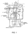
- FIG. 1 shows a schematic illustration of the directed vapor deposition process.
- the carrier gas stream 5 is created by a rarefied, inert gas supersonic expansion through a nozzle 30.
- the speed and flux of the atoms entering the chamber 4, the nozzle parameters, and the operating chamber pressure can all be varied leading to a wide range of accessible processing conditions.
- Critical to the process is the supersonic carrier gas stream maintained by achieving a high upstream pressure (i.e. the gas pressure prior to its entrance into the processing chamber), P u , and a lower chamber pressure, P o .
- the ratio of the upstream to downstream pressure along with the size and shape of the nozzle opening 31 controls the speed of the gas entering the chamber 4.
- the carrier gas molecular weight (compared to that of the vapor) and the carrier gas speed controls its effectiveness in redirecting the vapor atoms via binary collisions towards the substrate 20.
- alternative embodiments of the present invention process will provide the ability to evaporate from two or more individual source rods and the ability to ionize the evaporated flux using hollow cathode plasma activation.
- the aforementioned DVD process is schematically shown in FIG. 1 , improving the deposition efficiency, increasing the deposition rate and enhancing the coating uniformity.
- the hollow cathode system 58 is optional based on desired operations.
- the carrier gas 5 is realigned so that it is substantially in-line with the crucible 10. In this alignment, the carrier gas flow is placed completely or substantially around the crucible 10 so that the vapor flux 15 no longer has to be turned 90 degrees towards the substrate 20, but rather can be simply focused onto the substrate located directly above the evaporant source 25.
- the carrier gas 105 flows substantially parallel with the normal axis, identified as CL.
- the nozzle 30 has a nozzle gap or opening 32, through which the carrier gas 5 flows, is designed such that a more optimal carrier gas speed distribution for focusing the vapor 15 is produced. Also shown is the electron beam gun 3 and vacuum chamber 4.
- TBC's are typically applied at a very high temperature (e.g., 1050°C). This temperature is achieved by pre-heating the blade before it is entered into the chamber. Due to the configuration of the system in the present invention, such that the blade is placed directly above the source and the carrier gas flow rate may be decreased, the amount for radiant heat from the source is greatly increased and thus blade heating using a standard pre-heating furnace may be realized.
- a very high temperature e.g. 1050°C
- both the vapor and carrier gas flow pass through supersonic shock waves as the gas and vapor move away from the gas flow nozzle.
- shock waves affect the density and distribution of the vapor.
- the resulting atomic structure of growing film can be affected by the distance from the gas flow nozzle to the coating surface (relative to the shocks in the flow).
- the vapor is no longer incorporated directly into that carrier gas flow, its distribution and density will be less affected by the shocks in the system.
- the present invention process will become less critically dependent upon the position of gas flow nozzle and coating surface.
- the present invention system design will be able to more easily accommodate such parts while still producing the desired atomic structure.
- the pumping capacity required for DVD is a function of the nozzle opening area. Larger openings require more pumping capacity in order to reach the same chamber pressure than smaller openings.
- the nozzle opening size must be increased, and this is true for both configurations.
- the area increase for the present invention ring configuration is much less than for the conventional circular shaped opening. For example, if one assumes that increasing the source size from 0.0127 m to 0.0381 m requires a three fold increase in the nozzle diameter, the increased nozzle opening area can be calculated for both configurations.
- the circular opening would have a nine fold increase in area while the ring opening would have only a 2.76 fold increase.
- the benefit of increasing the source size is that the vapor emitting surface would be increased by nine fold, and in conjunction with the 3 to 4 time improvement in the deposition efficiency, could lead to a deposition rate which is more than 30 times higher than current DVD technology (i.e., greater than 500 ⁇ m/min. is then possible based on current deposition rates (of 15 to 20 ⁇ m/min.)).
- vapor phase mixing can be achieved by aligning two (or potentially more) sources 223, 224, 225 in line with a carrier gas flow 205 and using electron beam scanning 203 to uniformly heat both (or plurality of) sources.
- the use of the carrier gas jet in this embodiment not only scatters the vapor flux toward the substrate, leading to a potentially high MUE (and high deposition rates), but also randomizes the vapor trajectory facilitating vapor phase mixing of the two (or plurality of) fluxes 216.
- a high MUE would allow for the use of small diameter metal source materials, which could be spaced closely together to further improve the compositional uniformity of the coating, while still achieving a high rate of deposition.
- the composition of the deposited layer could be systematically controlled by altering the electron beam scan pattern to change the surface temperature (and thus the evaporation rate) of each source material.
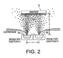
- the electron beam gun in the directed vapor deposition system has been equipped with a high speed e-beam scanning system (up to about 100 kHz) with a small beam spot size ( ⁇ about 0.5 mm) to allow multiple crucibles to be placed in close proximity to one another for precise heating and vapor mixing, Figure 2 .
- the carrier gas surrounds the vapor sources and allows the vapor from the neighboring melt pools to interdiffuse.
- the composition of the deposited layer can then be controlled by altering the electron beam scan pattern to change the temperature (and thus the evaporation rate) of each source material. In effect this is a splitting of the beam into two or more beams with precisely controllable power densities.
- the present invention DVD system enables the evaporation of several materials simultaneously and thus, precise composition control in the coating can be achieved.
- a single e-beam can be scanned across multiple, closely-spaced vapor sources for precise alloy or multilayer deposition.
- the water-cooled copper crucible and independent source feed motors make possible independent material feed and evaporation.
- the setup is shown schematically for Ni / Al / Pt evaporation.
- a single e-beam can be scanned across multiple, closely-spaced vapor sources for precise alloy or multilayer deposition.
- the water-cooled copper crucible and independent source feed motors make possible independent material feed and evaporation
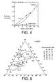
- FIG. 4 the effect of e-beam current on the required source material feed rate for constant evaporation is graphically shown.
- the feed rate gives a measure of the evaporation rate.
- the required source feed rate changes, and in turn the vapor concentration of each element in the carrier gas.
- the evaporation rate of each source is independent of those for the other sources.
- the result of altering the beam current is graphically shown in FIG. 4 where coatings of vastly different composition have been produced by incorporating different power density levels to each source.
- the coating composition can be altered. Shown is a Ni / Al / Pt ternary phase diagram showing the EDS measured compositions of coating deposited using different beam current combinations.
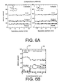
- FIG. 6A the composition of a Ni-Al-Pt coating is shown in the x and y direction across the substrate. It should be noted that the coating composition does not vary greatly across the entire 2.54 cm x 2.54 cm substrate. In addition, compositional uniformity in the through-thickness direction is also desired as inter-diffusion between the substrate and the bond coat can lead to the formation of nonprotective oxide layers, thus promoting TBC failure.
- FIG. 6B the through-thickness composition of a Ni / Al / Pt coating is schematically illustrated. The process provides a uniform composition throughout the bond coat and a sharp interface between the substrate and the bond coat displaying limited interdiffusion during processing. The uniform composition is provided along the entire cross section of the coating..
- a plasma activation unit is incorporated into the DVD system.
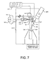
- plasma-activation in DVD is performed by a hollow-cathode plasma unit capable of producing a high-density plasma in the system's gas and vapor stream, See FIGS. 7-12 .
- the particular hollow cathode arc plasma technology used in DVD is able to ionize a large percentage of all gas and vapor species in the mixed stream flowing towards the coating surface. This ionization percentage in a low vacuum environment is unique to the DVD system.
- the plasma generates ions which can be accelerated towards the coating surface by either a self-bias or by an applied electrical potential.
- the DVD process has the ability to combine focused evaporation with plasma activation for rapid, efficient deposition of various crystal structures.
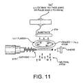
- the plasma device emits low energy electrons which ionize the vapor atoms and carrier gas. By properly biasing the substrate the impact energy the both species can be controlled.
- FIGS. 13A-13B The effect of plasma activation on the morphology of NiAl coatings is shown in SEM micrographs representations of FIGS. 13A-13B , wherein two nickel aluminide coatings are shown using identical DVD process conditions.
- FIG. 13A no plasma activation was used and in the second case, as shown in FIG. 13B , plasma activation using a plasma current of 120 A and a -75 V substrate bias was employed.
- a columnar coating resulted which is not expected to be useful for the TBC bond coat application.
- plasma activation is used, the columnar pores are removed and a NiAl layer with the proper bond coat morphology results, and thus a denser NiAl coating results.
- Other levels of plasma current and substrate bias may be utilized as desired.
- the present invention DVD system is comprises a vacuum chamber 304, a rod feed evaporator 325 that is placed which is heated up to evaporation temperature of evaporant by the electron-beam of an electron gun 303 and provides the vapor for coating of substrates 320. Vaporized evaporant is entrained in the supersonic gas and vapor stream 315 formed by the nozzle 330.
- the substrate(s) 320 are fixed at a substrate holder 343 which enables shift of the substrate in any independent direction and to be swiveled.
- the translation motion in the horizontal plan allows the exposed surface areas of the substrate to the vapor stream for defined dwelling times and control of the local coating thickness.
- the vertical motion can be used to keep constant the distance between plasma and surface for curved substrates.
- Swivel motion in coordination with the translation motions, can be used to enable the coating of complete three-dimensional parts or can be used also to change the incidence angle of the vapor particles in the course of layer coating in a defined way for getting distinct layer properties.
- the hollow cathode (arc source) 358 is placed laterally below substrate holder 343 with a short distance between the cathode orifice 359 and the gas and vapor stream 315.
- the anode 360 is arranged opposite the cathode orifice 359 (i.e., on an approximate distant side of the stream 315) so that the fast electrons and the plasma discharge 361 crosses the gas and vapor stream 315.
- the fixtures for the cathode 346 and for the anode 347 provides the ability to adjust the distance of the cathode 358 and the anode 360, thereby influencing the diameter and the shape of gas and vapor stream 315.
- the plasma discharge 361 is in close proximity (arranged with short distance) to the surface of the substrate 320 enabling close contact between dense plasma and the substrate surface to be coated.
- the anode power line 349 from the power generator 350 to the anode 360 is arranged closely and in parallel with both the plasma discharge 59 and the cathode power line 351, which runs from the cathode to the power generator 350.
- a bias generator 352 is applied that allows for generation of a positive, a negative or a periodically alternating voltage between the substrate 320 and the plasma 361.
- FIG. 8A demonstrates the horizontal shift of the cathode 358 and anode 360 from an initial position to a secondary position, while still maintaining the plasma discharge.
- FIG. 8B demonstrates the horizontal turn of the cathode 358 and anode 360 arrangement away from the vapor-gas-jet 361, while still maintaining the plasma discharge.
- FIG. 9A demonstrates the displacement of the plasma discharge 361 away from the gas and vapor stream 315 by moving sideward (i.e., horizontally) the anode 360 only.
- FIG. 9B demonstrates the displacement of the plasma discharge 361 away from the gas and vapor stream 315 by moving only the cathode 358 sideward.
- FIG.10 demonstrates the displacement of the plasma discharge 361 away from the gas and vapor stream 315 by switching the power supply 350 with the switch 353 from the active anode 360 to an auxiliary anode 354.
- FIG. 11 provides an enlarged partial view of the embodiment shown in FIG. 7 .
- FIG. 12 schematically illustrates an alternative embodiment wherein the instant system and method has the main gas and vapor stream 315 which is deflected from the vertical direction 371 by interaction with the working gas flow 372 of the hollow cathode 358 escaping from the cathode orifice 359 resulting in a bending of the vapor stream 375 away from the cathode side.
- the directed gas injection 373 is in an opposed position to the cathode through a gas channel 370 integrated in the anode block 10 and enables the compensation of deflection. Therefore, the resulting gas and vapor stream 374 flows in the vertical direction again. Overcompensation will result in a bending of the main gas and vapor stream 376 towards the cathode side.
- the same channel 370 can be used for clear gas influx to keep free the anode or parts of the anode surface from insulating contamination. This clear gas influx feature can been done independently or in combination with the bending effect injection of the anode.
- a plasma made up of the ionized evaporant and/or carrier gas atoms can be utilized including the use of microwave or other radio frequency discharges.
- plasma enhanced deposition is possible under the action of a self bias or one applied externally to the substrate.
- the applied bias can be static (DC) or oscillated (RF) or pulsed.
- the present invention DVD process allows for the creation of novel bondcoat concepts.
- Some example embodiments include, but not limited thereto 1) multilayered NiAl / Alumina composites, and 2) nanoparticle NiAl / alumina composites. Both of these embodiments increase the strength of the bond coat which in turn leads to increased TBC system lifetimes.
- the multilayer composites embodiment is produced by co-evaporation ofNi and Al in a plasma environment. At various times during the deposition, the Ni evaporation is stopped and oxygen is fed into the carrier gas stream resulting in the deposition of alpha alumina. By repeating this process, multilayer coatings of NiAl and alumina are created. Such structures will further improve TBC performance as reduced diffusion in the alumina layers will prevent the migration of elements in the substrate to the top of the bond coat where they can promote nonprotective oxide growth. Other layers which reduce substrate / bond coat interdiffusion may also be added.
- NiAl / alumina nanoparticle composites embodiment is produced by codeposition of NiAl and alumina nanoclusters.
- the nano clusters are grown in a separate higher pressure region and then injected at high velocity into the DVD chamber using a choked nozzle. These nanoclusters impinge on the substrate embedding themselves into the depositing layer and are subsequently buried by further NiAl deposition
- the DVD crucible design enables the simultaneous evaporation of four material sources.
- Another aspect of the present invention method and system is directed at the capability to "steer" vapor flux from the nozzle by changing the pressure in the nozzle on either side of the vapor source.
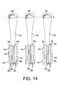
- FIG. 14 is a schematic illustration showing a multiple crucible / jet arrangement.
- the nozzles include nozzle gaps 132(a), 132(b), 132(c) where carrier gas streams flow therefrom.
- the nozzle gaps are non-angular 141(a), 141(b), 141(c) having a ring-shape 133(a), 133(b), 133(c).
- Each source is heated with an electron beam (using either single beam scanning gun or multiple e-beam guns) and the vapor is directed onto a turbine blade at high efficiency and rate.
- the vapor flux distribution (115(a), 115(b), 115(c)), is adjusted to the size of the blade or target (120(a), 120(b), 120(c)). This allows multiple blades or targets to be simultaneously coated at high rate to result in a very high process throughput. Steering of the vapor is accomplished using non-angular symmetric nozzles.
- an additional electron beam 103 is employed for each source 105.
- a preferred method is to use the high frequency scanning capability of the electron beam to maintain evaporation from many sources simultaneously.
- an additional aspect of the present invention allows for steering of the vapor using angular symmetric nozzles defined by angular channels 142(a), 142(b), 142(c).
- multiple sources 125(a), 125(b), 125(c), carrier gas streams 105(a), 105(b), 105(c), and nozzles 130(a), 130(b), 130(c) are employed to steer the vapor flux onto widely spaced individual components.
- the schematic illustration of this embodiment shows a multiple nozzle per crucible configuration in which nozzles are closely spaced so that one electron beam can be scanned across each source for simultaneous heating. The orientation of the nozzle openings are altered to steer the flux onto widely spaced components (e.g., targets/substrate).
- multiple sources 125(a), 125(b), 125(c)
- carrier gas streams 105(a), 105(b), 105(c)
- nozzles 130(a), 130(b), 130(c)
- this embodiment uses multiple sources to moderately focus a vapor flux, which results in a large uniform vapor flux distribution 117 and allows for the uniform coating of large turbine blades such as those used in industrial power generation turbines.
- this embodiment uses multiple crucibles and jets arrangement in which a vapor flux is focused to result in a large uniform vapor flux distribution 117 such that a large number of small turbine blades can be placed into the vapor and be uniformly coated at moderately high efficiency and rate.
- An advantage of this approach is that less carrier gas flow is required while more blades per coating cycle may be coated. The proper approach is dependent on the size of the blades being coated. This approach may be appropriate when blades which are much smaller or larger than the uniform area of a individual jet.
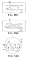
- alternative embodiments utilize elongated elliptical ring gaps 134 and, optionally elongated elliptical source openings 127, to produce an elliptical vapor flux 116 distribution,.
- This is of interest for non-circular shaped substrates such as turbine blades 120, in which a higher deposition efficiency can be realized if the shape of the vapor flux distribution is tailored to the size and shape of the part to be coated.
- This approach allows for one to not only apply a coating to the desired area of the part, but also to prevent coating on an area that requires subsequent part manipulation tooling or locations 121 on the part which do not require a turbine blade.
- the dashed lines shown in FIG. 18(C) indicate a circular vapor flux compared to the desirable elliptical vapor flux 116 distribution of the present invention. The circular case would result in a larger portion of the vapor not being utilized.
- the nozzle gaps and source shapes may be of a variety of shapes, alignments, and quantity.
- FIG. 19(A) schematically shows the plan view of a cross-hatch-shaped nozzle gap 139 in relation to the nozzle 130 and source 125.
- FIG. 19(B) schematically shows the plan view of an elliptical-shaped nozzle gap 135 in relation to the nozzle 130 and source 125.
- FIG. 19(C) schematically shows the plan view wherein the ring-shaped nozzle gaps 133 (at least two or more) are concentric or substantially concentric.
- FIGS. 19(D) and 19(E) the ring gaps or channels may be partitioned so that a plurality of segments comprise the overall gap or channel.
- FIGS. 19(D) and 19(E) schematically show the plan view of a segmented elliptical 138 and segmented ring gap 136.
- the present invention describes a series of steps, and an apparatus for use therewith for applying a bond coating to a substrate of a thermal barrier coating system using an electron beam directed vapor deposition technique.
- Some advantages of the present invention process and apparatus but not limited thereto is that it provides for the materials utilization efficiency of the process to be improved, deposition rate increased, coating uniformity improved, multiple blade coating during each coating cycle, carrier gas flow costs optimized, and blades to be heated to the desired temperature.
- this invention allows the ratio of carrier gas flow to vapor molecular concentration to be dramatically reduced while increasing the material utilization efficiency of the technology. Accordingly, this breakthrough has significant positive economic implications for the utility of the process.
- the present invention provides the use of an electron beam directed vapor deposition (DVD) approach wherein the vaporized material is entrained in the carrier gas jet and deposited onto the substrate at high rate and with a high materials utilization efficiency.
- DVD electron beam directed vapor deposition
- plasma enhancement multisource crucibles and process condition control, the morphology, composition and grain size of deposited layers are controlled. The result is a low cost deposition approach for applying bond coats which have compositions which are difficult to deposit using other approaches.
Landscapes
- Chemical & Material Sciences (AREA)
- Engineering & Computer Science (AREA)
- Metallurgy (AREA)
- Chemical Kinetics & Catalysis (AREA)
- Materials Engineering (AREA)
- Mechanical Engineering (AREA)
- Organic Chemistry (AREA)
- Inorganic Chemistry (AREA)
- Health & Medical Sciences (AREA)
- Toxicology (AREA)
- Ceramic Engineering (AREA)
- Physical Vapour Deposition (AREA)
- Coating Apparatus (AREA)
- Electroplating Methods And Accessories (AREA)
Claims (29)
- Procédé pour former un système de revêtement à barrière thermique, le procédé comprenant les étapes qui consistent à :m) présenter au moins un substrat (20) à une chambre (4);n) former un revêtement d'accrochage sur au moins une partie d'au moins ledit substrat en procédant aux étapes suivantes:o) présenter au moins une source d'évaporant à ladite chambre,p) présenter au moins un flux de gaz porteur (5) à ladite chambre,q) percuter ladite source d'évaporant au moins avec un faisceau d'électrons (2) au moins dans ladite chambre pour générer un flux (15) de vapeur en évaporation dans une direction principale vers ledit substrat, etr) entraîner ledit flux (15) de vapeur en évaporation généré au moins par ledit flux (5) de gaz porteur au moins, où ledit gaz porteur est essentiellement parallèle à ladite direction principale et entoure essentiellement ledit flux de vapeur en évaporation, où ledit flux de vapeur en évaporation revêt au moins partiellement ledit substrat au moins pour former ledit revêtement d'accrochage; ets) déposer une couche d'isolation thermique sur ledit revêtement d'accrochage.
- Procédé de la revendication 1, comprenant en plus le traitement thermique dudit substrat pour permettre la formation dudit revêtement d'accrochage.
- Procédé d la revendication 2, dans lequel le traitement thermique dudit substrat comprend le chauffage à une plage de températures d'environ 800 C à environ 1500 C.
- Procédé de la revendication 1, dans lequel ladite présentation d'au moins l'un dudit substrat inclut la présentation dudit substrat à une chambre ayant une de pression de fonctionnement se trouvant dans la plage d'environ 0,1 à environ 32, 350 PA.
- Procédé de la revendication 1, comprenant en plus : ladite chambre contient en plus un système de polarisation de substrat capable d'appliquer un potentiel alternatif ou continu à au moins l'un desdits substrats, de percuter ledit au moins l'un dudit flux de vapeur en évaporation et au moins l'un dudit flux de gaz porteur avec un gaz de travail généré par au moins une source d'activation plasma à arc cathodique creux pour ioniser ledit au moins l'un dudit flux de vapeur générée et au moins l'un dudit flux de gaz porteur; et
attirer ledit flux de vapeur générée ionisé et ledit flux de gaz porteur vers une surface du substrat en permettant une auto-polarisation desdits gaz ionisé et flux de vapeur ou dudit potentiel alternatif ou continu afin de ramener le flux ionisé vers ledit substrat. - Procédé de la revendication 5, lesdits électrons générés de ladite source cathodique creuse sont régulés pour une direction à travers des variations dans la quantité de gaz de travail passant à travers ladite source cathodique creuse.
- Procédé de la revendication 5, dans lequel la distance entre ladite source cathodique et ledit flux de vapeur en évaporation généré est régulée pour l'ionisation de la totalité du flux de vapeur en évaporation généré.
- Procédé de la revendication 1, comprenant en plus au moins une buse, où ledit flux de gaz porteur au moins est généré de ladite buse au moins et ladite source d'évaporant au moins est disposée dans ladite buse au moins, où ladite buse au moins comprend :au moins un jeu de buse duquel s'écoule ledit gaz porteur au moins ; et au moins un dispositif de retenue de l'évaporant pour retenir ladite source d'évaporant au moins, ledit dispositif de retenue de l'évaporant étant au moins essentiellement entouré par ledit jeu de buse au moins.
- Procédé de la revendication 8, dans lequel ledit dispositif de retenue de l'évaporant est un creuset.
- Procédé de la revendication 8, dans lequel ledit jeu de buse au moins est défini par une forme choisie du groupe constitué d'une forme annulaire, d'une forme elliptique, d'une forme elliptique allongée, d'une forme quadrillée, d'une forme annulaire segmentée, d'une forme elliptique segmentée, et d'une forme elliptique allongée segmentée.
- Procédé de la revendication 8, dans lequel ladite buse au moins comprend une buse convergente/divergente.
- Procédé de la revendication 8, comprenant en plus le fait de:prévoir une pluralité desdites buses, où lesdits jeux de buses sont des canaux non angulaires; etprévoir une pluralité desdits faisceaux d'électrons, où un faisceau d'électrons individuel desdits faisceaux d'électrons percute lesdites sources individuelles pour générer un flux de vapeur en évaporation afin de revêtir au moins partiellement une pluralité desdits substrats, chacun desdits substrats étant revêtu respectivement à partir d'une source singulière parmi ladite source d'évaporant.
- Procédé de la revendication 8, comprenant en plus le fait de:prévoir une pluralité desdites buses, où lesdits jeux de buses sont des canaux non angulaires; etprévoir une pluralité desdits faisceaux d'électrons, où un faisceau d'électrons individuel desdits faisceaux d'électrons percute lesdites sources individuelles pour générer un grand flux de vapeur en évaporation afin de revêtir au moins partiellement un substrat singulier dudit substrat, ledit substrat étant revêtu à partir de ladite pluralité desdites sources d'évaporant.
- Procédé de la revendication 8, comprenant en plus le fait de :prévoir une pluralité desdites buses, où lesdits jeux de buses sont des canaux angulaires ; etprévoir un faisceau d'électrons singulier dudit faisceau d'électrons, où ledit faisceau d'électron percute une source individuelle desdites sources pour générer un flux de vapeur en évaporation afin de revêtir au moins partiellement une pluralité desdits substrats, chacun desdits substrats étant revêtu respectivement à partir d'une source singulière de ladite source d'évaporant.
- Procédé de la revendication 8, comprenant en plus le fait de:prévoir une pluralité desdites buses, où lesdits jeux de buses sont des canaux angulaires ; etprévoir un faisceau d'électrons singulier dudit faisceau d'électrons, où ledit faisceau d'électron singulier percute une source individuelle desdites sources d'évaporant pour générer un grand flux de vapeur en évaporation afin de revêtir au moins partiellement un substrat singulier dudit substrat, ledit substrat étant revêtu à partir de ladite pluralité desdites sources d'évaporant.
- Procédé de l'une quelconque des revendications 12, 13, 14 ou 15, dans lequel lesdites sources d'évaporant ont essentiellement la même composition chimique les unes par rapport aux autres.
- Procédé de la revendication 16, dans lequel au moins l'une desdites sources d'évaporant est un matériau choisi du groupe constitué de : NiAl, PtAl, Ni, Al, Pt, NiAlPt, et NiPt.
- Procédé de la revendication 16, dans lequel au moins l'une desdites sources d'évaporant est faite à partir d'alliages formés d'un ou de plusieurs matériaux choisis parmi le groupe constitué de : NiAl, PtAl, Ni, Al, Pt, NiAlPt, et NiPt.
- Procédé de l'une quelconque des revendications 12, 13, 14 ou 15, dans lequel au moins l'une desdites sources d'évaporant possède des compositions chimiques différentes par rapport aux autres.
- Procédé de la revendication 19, comprenant en plus la combinaison d'au moins deux desdites sources d'évaporant après l'impact mais avant d'atteindre lesdits substrats.
- Procédé de la revendication 19, dans lequel au moins l'une desdites sources d'évaporant est un matériau choisi du groupe constitué de : NiAl, PtAl, Ni, Al, Pt, NiAlPt, et NiPt.
- Procédé de la revendication 19, dans lequel au moins l'une desdites sources d'évaporant est réalisée à partir d'alliages formés d'un ou de plusieurs matériaux choisis du groupe constitué de : NiAl, PtAl, Ni, Al, Pt, NiAlPt, et NiPt.
- Procédé de la revendication 4, comprenant en plus les étapes qui consistent à:a) interrompre la progression de la production du flux évaporé pour former ledit revêtement d'accrochage ; etb) prévoir de l'oxygène dans ledit flux de gaz porteur au moins, entraînant ainsi le dépôt d'alumine alpha sur ledit substrat au moins.
- Procédé de la revendication 23, dans lequel l'étape "a" et l'étape "b" sont répétées un nombre de fois souhaité.
- Procédé de la revendication 4, comprenant les étapes qui consistent à:a) prévoir des nano-agrégats sous une pression supérieure à ladite pression de la chambre ; etb) injecter lesdits nano-agrégats à une vitesse élevée dans ladite chambre, entraînant ainsi des nano-agrégats percutés dans ledit revêtement d'accrochage.
- Procédé de la revendication 4, dans lequel un champ de fréquence radio est utilisé pour ioniser l'évaporant et/ou le flux de gaz porteur et une tension de polarisation RF ou statique et/ou d'auto-polarisation appliquée au substrat est utilisée pour apporter un dépôt assisté par plasma du revêtement.
- Procédé de la revendication 4, comprenant en plus : un procédé pour créer du plasma incluant partiellement ou en totalité un évaporant ionisé ou un flux de gaz porteur qui est utilisé en combinaison avec une tension de polarisation RF ou DC appliquée ou d'auto-polarisation audit substrat pour apporter un dépôt assisté par plasma d'un revêtement.
- Composant ayant un système de revêtement à barrière thermique sur un substrat associé, le système de revêtement à barrière thermique comprenant : un revêtement d'accrochage déposé sur au moins une partie dudit substrat par une technique de dépôt orienté en phase vapeur (DVD) ; et une couche d'isolation thermique recouvrant au moins une partie dudit revêtement d'accrochage, où ledit composant est produit par le procédé de la revendication 1.
- Composant de la revendication 28, dans lequel ledit composant est au moins l'un d'un composant du moteur d'une turbine à gaz, d'un composant d'un moteur diesel, d'une aube de turbine, et d'un déflecteur d'air.
Applications Claiming Priority (3)
| Application Number | Priority Date | Filing Date | Title |
|---|---|---|---|
| US31828601P | 2001-09-10 | 2001-09-10 | |
| US318286P | 2001-09-10 | ||
| PCT/US2002/028654 WO2003028428A2 (fr) | 2001-09-10 | 2002-09-10 | Procede et appareil d'application de revetements d'alliages metalliques |
Publications (4)
| Publication Number | Publication Date |
|---|---|
| EP1436441A2 EP1436441A2 (fr) | 2004-07-14 |
| EP1436441A4 EP1436441A4 (fr) | 2004-11-24 |
| EP1436441B1 true EP1436441B1 (fr) | 2009-12-02 |
| EP1436441B2 EP1436441B2 (fr) | 2012-11-28 |
Family
ID=23237501
Family Applications (1)
| Application Number | Title | Priority Date | Filing Date |
|---|---|---|---|
| EP02800327A Expired - Lifetime EP1436441B2 (fr) | 2001-09-10 | 2002-09-10 | Procede d'application de revetements d'alliages metalliques et composant revêtu |
Country Status (6)
| Country | Link |
|---|---|
| US (2) | US8124178B2 (fr) |
| EP (1) | EP1436441B2 (fr) |
| AT (1) | ATE450631T1 (fr) |
| AU (1) | AU2002356523A1 (fr) |
| DE (1) | DE60234620D1 (fr) |
| WO (1) | WO2003028428A2 (fr) |
Families Citing this family (39)
| Publication number | Priority date | Publication date | Assignee | Title |
|---|---|---|---|---|
| US8124178B2 (en) * | 2001-09-10 | 2012-02-28 | University Of Virginia Patent Foundation | Method and apparatus application of metallic alloy coatings |
| US7556695B2 (en) * | 2002-05-06 | 2009-07-07 | Honeywell International, Inc. | Apparatus to make nanolaminate thermal barrier coatings |
| AU2003295851A1 (en) * | 2002-11-21 | 2004-06-18 | University Of Virginia Patent Foundation | Bond coat for a thermal barrier coating systemand related method thereof |
| US7509734B2 (en) | 2003-03-03 | 2009-03-31 | United Technologies Corporation | Repairing turbine element |
| US7216428B2 (en) * | 2003-03-03 | 2007-05-15 | United Technologies Corporation | Method for turbine element repairing |
| US8122600B2 (en) * | 2003-03-03 | 2012-02-28 | United Technologies Corporation | Fan and compressor blade dovetail restoration process |
| US7128986B2 (en) * | 2003-10-16 | 2006-10-31 | Seagate Technology, Llc | Nanoclustered magnetic materials for high moment write pole applications |
| US6979498B2 (en) * | 2003-11-25 | 2005-12-27 | General Electric Company | Strengthened bond coats for thermal barrier coatings |
| US20050205415A1 (en) | 2004-03-19 | 2005-09-22 | Belousov Igor V | Multi-component deposition |
| US7404986B2 (en) | 2004-05-07 | 2008-07-29 | United Technologies Corporation | Multi-component deposition |
| US8084086B2 (en) * | 2005-06-30 | 2011-12-27 | University Of Virginia Patent Foundation | Reliant thermal barrier coating system and related methods and apparatus of making the same |
| US20070207266A1 (en) * | 2006-02-15 | 2007-09-06 | Lemke Harald K | Method and apparatus for coating particulates utilizing physical vapor deposition |
| US20080292903A1 (en) * | 2007-05-25 | 2008-11-27 | United Technologies Corporation | Coated gas turbine engine component repair |
| US8709160B2 (en) | 2008-08-22 | 2014-04-29 | United Technologies Corporation | Deposition apparatus having thermal hood |
| US8404047B2 (en) | 2008-09-16 | 2013-03-26 | United Technologies Corporation | Electron beam vapor deposition apparatus and method |
| US8343591B2 (en) | 2008-10-24 | 2013-01-01 | United Technologies Corporation | Method for use with a coating process |
| US20100189929A1 (en) * | 2009-01-28 | 2010-07-29 | Neal James W | Coating device and deposition apparatus |
| PL2401232T3 (pl) | 2009-02-24 | 2016-10-31 | Bezpośrednie napylanie próżniowe wspomagane plazmą z współosiowej drążonej katody i związany z nim sposób | |
| US8419857B2 (en) | 2009-03-31 | 2013-04-16 | United Technologies Corporation | Electron beam vapor deposition apparatus and method of coating |
| UA92556C2 (uk) * | 2009-06-10 | 2010-11-10 | Астромонт Лимитед | Спосіб одержання наночастинок системи метал-кисень із заданим складом електронно-променевим випаровуванням і конденсацією у вакуумі |
| KR101084234B1 (ko) * | 2009-11-30 | 2011-11-16 | 삼성모바일디스플레이주식회사 | 증착원, 이를 구비하는 증착 장치 및 박막 형성 방법 |
| WO2011085109A1 (fr) * | 2010-01-06 | 2011-07-14 | Directed Vapor Technologies International, Inc. | Procédé de co-évaporation et de dépôt de matériaux à des pressions de vapeur différentes |
| DE102010017896A1 (de) * | 2010-04-21 | 2011-10-27 | Ald Vacuum Technologies Gmbh | Vorrichtung und Verfahren zum Beschichten von Substraten nach dem EB/PVD-Verfahren |
| WO2012027442A1 (fr) * | 2010-08-27 | 2012-03-01 | Rolls-Royce Corporation | Revêtements barrières environnementales à base de silicate de terres rares |
| US8642140B2 (en) * | 2011-03-09 | 2014-02-04 | United Technologies Corporation | Ceramic coating deposition |
| US8541069B2 (en) * | 2011-04-11 | 2013-09-24 | United Technologies Corporation | Method of guided non-line of sight coating |
| US9023422B1 (en) * | 2011-08-31 | 2015-05-05 | Maxim Integrated Products, Inc. | High rate deposition method of magnetic nanocomposites |
| WO2013085625A2 (fr) * | 2011-10-17 | 2013-06-13 | Directed Vapor Technologies International | Revêtements de barrière thermique et environnementale résistant à l'érosion et aux chocs |
| US9581042B2 (en) | 2012-10-30 | 2017-02-28 | United Technologies Corporation | Composite article having metal-containing layer with phase-specific seed particles and method therefor |
| US9527107B2 (en) | 2013-01-11 | 2016-12-27 | International Business Machines Corporation | Method and apparatus to apply material to a surface |
| WO2015073098A2 (fr) | 2013-08-27 | 2015-05-21 | University Of Virginia Patent Foundation | Structures spatiales tridimensionnelles assemblées à partir de pièces de composants et leurs procédés de fabrication |
| US10233533B2 (en) * | 2014-01-09 | 2019-03-19 | United Technologies Corporation | Coating process using gas screen |
| EP3189298A1 (fr) | 2014-09-04 | 2017-07-12 | University Of Virginia Patent Foundation | Systèmes d'atténuation d'impulsions pour impacts de milieux et leurs procédés associés |
| NL2013836B1 (en) * | 2014-11-20 | 2016-10-10 | Univ Delft Tech | Production of nanostructured materials. |
| US10184759B2 (en) | 2015-11-17 | 2019-01-22 | University Of Virgina Patent Foundation | Lightweight ballistic resistant anti-intrusion systems and related methods thereof |
| GB201600645D0 (en) * | 2016-01-13 | 2016-02-24 | Rolls Royce Plc | Improvements in additive layer manufacturing methods |
| US11866816B2 (en) * | 2016-07-06 | 2024-01-09 | Rtx Corporation | Apparatus for use in coating process |
| US10724133B2 (en) * | 2016-09-14 | 2020-07-28 | Raytheon Technologies Corporation | EBPVD columnated vapor stream |
| JP2021505776A (ja) * | 2017-12-06 | 2021-02-18 | アリゾナ・シン・フィルム・リサーチ・エルエルシー | 金属およびセラミック材料の付着のための付加製造のためのシステムおよび方法 |
Family Cites Families (55)
| Publication number | Priority date | Publication date | Assignee | Title |
|---|---|---|---|---|
| US3620815A (en) * | 1969-03-13 | 1971-11-16 | United Aircraft Corp | Vapor collimation in vacuum deposition of coatings |
| JPS5472954A (en) * | 1977-11-23 | 1979-06-11 | Noboru Tsuya | Semiconductor thin film and method of fabricating same |
| US4272612A (en) * | 1979-05-09 | 1981-06-09 | The United States Of America As Represented By The Secretary Of The Army | Erosion lithography to abrade a pattern onto a substrate |
| US4439463A (en) * | 1982-02-18 | 1984-03-27 | Atlantic Richfield Company | Plasma assisted deposition system |
| JPS591676A (ja) * | 1982-06-29 | 1984-01-07 | Citizen Watch Co Ltd | イオンブレ−テイング装置 |
| US4777908A (en) * | 1986-11-26 | 1988-10-18 | Optical Coating Laboratory, Inc. | System and method for vacuum deposition of thin films |
| JPS63274762A (ja) | 1987-05-01 | 1988-11-11 | Ulvac Corp | 反応蒸着膜の形成装置 |
| JP2709162B2 (ja) * | 1989-11-15 | 1998-02-04 | 株式会社日立製作所 | マイクロ波プラズマ処理装置 |
| US5356673A (en) * | 1991-03-18 | 1994-10-18 | Jet Process Corporation | Evaporation system and method for gas jet deposition of thin film materials |
| DE4304613C1 (de) | 1993-02-16 | 1994-05-26 | Fraunhofer Ges Forschung | Verfahren zur Stabilisierung der Plasmaerzeugung mittels Elektronenstrahlverdampfer |
| US5356718A (en) * | 1993-02-16 | 1994-10-18 | Ppg Industries, Inc. | Coating apparatus, method of coating glass, compounds and compositions for coating glasss and coated glass substrates |
| US5560779A (en) * | 1993-07-12 | 1996-10-01 | Olin Corporation | Apparatus for synthesizing diamond films utilizing an arc plasma |
| DE4412906C1 (de) * | 1994-04-14 | 1995-07-13 | Fraunhofer Ges Forschung | Verfahren und Einrichtung für die ionengestützte Vakuumbeschichtung |
| AU3708495A (en) * | 1994-08-01 | 1996-03-04 | Franz Hehmann | Selected processing for non-equilibrium light alloys and products |
| US5464667A (en) | 1994-08-16 | 1995-11-07 | Minnesota Mining And Manufacturing Company | Jet plasma process and apparatus |
| US5534314A (en) * | 1994-08-31 | 1996-07-09 | University Of Virginia Patent Foundation | Directed vapor deposition of electron beam evaporant |
| US5573682A (en) † | 1995-04-20 | 1996-11-12 | Plasma Processes | Plasma spray nozzle with low overspray and collimated flow |
| DE19544584A1 (de) * | 1995-11-30 | 1997-06-05 | Leybold Ag | Vakuumbeschichtungsanlage mit einem in der Vakuumkammer angeordneten Tiegel zur Aufnahme von zu verdampfendem Material |
| US5628464A (en) * | 1995-12-13 | 1997-05-13 | Xerox Corporation | Fluidized bed jet mill nozzle and processes therewith |
| US6123997A (en) * | 1995-12-22 | 2000-09-26 | General Electric Company | Method for forming a thermal barrier coating |
| US5736073A (en) * | 1996-07-08 | 1998-04-07 | University Of Virginia Patent Foundation | Production of nanometer particles by directed vapor deposition of electron beam evaporant |
| US6258467B1 (en) * | 2000-08-17 | 2001-07-10 | Siemens Westinghouse Power Corporation | Thermal barrier coating having high phase stability |
| AUPO850597A0 (en) * | 1997-08-11 | 1997-09-04 | Silverbrook Research Pty Ltd | Image processing method and apparatus (art01a) |
| US6172331B1 (en) * | 1997-09-17 | 2001-01-09 | General Electric Company | Method and apparatus for laser drilling |
| SG71151A1 (en) * | 1997-09-17 | 2000-03-21 | Gen Electric | Bond coat for a thermal barrier coating system and method therefor |
| US6096381A (en) * | 1997-10-27 | 2000-08-01 | General Electric Company | Process for densifying and promoting inter-particle bonding of a bond coat for a thermal barrier coating |
| US6012652A (en) * | 1998-01-30 | 2000-01-11 | Mobil Oil Corporation | Atomizing nozzle and method of use thereof |
| US6168874B1 (en) * | 1998-02-02 | 2001-01-02 | General Electric Company | Diffusion aluminide bond coat for a thermal barrier coating system and method therefor |
| US7136173B2 (en) * | 1998-07-09 | 2006-11-14 | Acm Research, Inc. | Method and apparatus for end-point detection |
| DE19841012C1 (de) | 1998-09-08 | 2000-01-13 | Fraunhofer Ges Forschung | Einrichtung zum plasmaaktivierten Bedampfen im Vakuum |
| DE19845803C2 (de) † | 1998-09-30 | 2002-10-17 | Siemens Ag | Verfahren zum Vakuumbeschichten von Metallbauteilen |
| US6291084B1 (en) * | 1998-10-06 | 2001-09-18 | General Electric Company | Nickel aluminide coating and coating systems formed therewith |
| US6153313A (en) * | 1998-10-06 | 2000-11-28 | General Electric Company | Nickel aluminide coating and coating systems formed therewith |
| US6306524B1 (en) * | 1999-03-24 | 2001-10-23 | General Electric Company | Diffusion barrier layer |
| US6478931B1 (en) * | 1999-08-06 | 2002-11-12 | University Of Virginia Patent Foundation | Apparatus and method for intra-layer modulation of the material deposition and assist beam and the multilayer structure produced therefrom |
| US6273678B1 (en) * | 1999-08-11 | 2001-08-14 | General Electric Company | Modified diffusion aluminide coating for internal surfaces of gas turbine components |
| AU7993400A (en) * | 1999-10-04 | 2001-05-10 | Textron Inc. | Method and system for high pressure liquid injection of turf seed |
| US7194197B1 (en) * | 2000-03-16 | 2007-03-20 | Global Solar Energy, Inc. | Nozzle-based, vapor-phase, plume delivery structure for use in production of thin-film deposition layer |
| EP1409762A4 (fr) | 2000-05-23 | 2007-02-28 | Univ Virginia | Procede et appareil de depot par plasma sous vide |
| SG106639A1 (en) * | 2000-10-10 | 2004-10-29 | Gen Electric | Apparatus and method for introducing small amounts of refractory elements into a vapor deposition coating |
| US6641673B2 (en) * | 2000-12-20 | 2003-11-04 | General Electric Company | Fluid injector for and method of prolonged delivery and distribution of reagents into plasma |
| WO2002087787A1 (fr) | 2001-04-30 | 2002-11-07 | University Of Virginia Patent Foundation | Procede et appareil permettant l'application efficace d'un revetement de substrat |
| US8124178B2 (en) * | 2001-09-10 | 2012-02-28 | University Of Virginia Patent Foundation | Method and apparatus application of metallic alloy coatings |
| AU2003225170A1 (en) * | 2002-04-25 | 2003-11-10 | University Of Virginia Patent Foundation | Apparatus and method for high rate uniform coating, including non-line of sight |
| WO2004011688A2 (fr) * | 2002-07-25 | 2004-02-05 | University Of Virginia Patent Foundation | Procede et appareil de dispersion de revetements de liaison renforces pour revetements barrieres thermiques |
| AU2003287691A1 (en) * | 2002-11-12 | 2004-06-03 | University Of Virginia Patent Foundation | Extremely strain tolerant thermal protection coating and related method and apparatus thereof |
| AU2003295851A1 (en) * | 2002-11-21 | 2004-06-18 | University Of Virginia Patent Foundation | Bond coat for a thermal barrier coating systemand related method thereof |
| WO2005047202A2 (fr) * | 2003-07-29 | 2005-05-26 | University Of Virginia Patent Foundation | Procede d'application d'un revetement de barriere thermique et structure obtenue |
| US8110043B2 (en) * | 2004-01-08 | 2012-02-07 | University Of Virginia Patent Foundation | Apparatus and method for applying coatings onto the interior surfaces of components and related structures produced therefrom |
| US8084086B2 (en) * | 2005-06-30 | 2011-12-27 | University Of Virginia Patent Foundation | Reliant thermal barrier coating system and related methods and apparatus of making the same |
| WO2009023744A1 (fr) * | 2007-08-13 | 2009-02-19 | University Of Virginia Patent Foundation | Synthèse de batterie à film mince par dépôt par évaporation sous vide dirigée |
| PL2401232T3 (pl) * | 2009-02-24 | 2016-10-31 | Bezpośrednie napylanie próżniowe wspomagane plazmą z współosiowej drążonej katody i związany z nim sposób | |
| US8153958B2 (en) * | 2009-07-10 | 2012-04-10 | Sphere Renewable Energy Corp. | Method and apparatus for producing hyperthermal beams |
| WO2013106006A1 (fr) * | 2011-03-15 | 2013-07-18 | Directed Vapor Technologies International | Procédé d'application de revêtements en alliage d'aluminium pour la protection de l'acier contre la corrosion |
| US8541069B2 (en) * | 2011-04-11 | 2013-09-24 | United Technologies Corporation | Method of guided non-line of sight coating |
-
2002
- 2002-09-10 US US10/489,090 patent/US8124178B2/en active Active
- 2002-09-10 AT AT02800327T patent/ATE450631T1/de not_active IP Right Cessation
- 2002-09-10 DE DE60234620T patent/DE60234620D1/de not_active Expired - Lifetime
- 2002-09-10 WO PCT/US2002/028654 patent/WO2003028428A2/fr not_active Ceased
- 2002-09-10 AU AU2002356523A patent/AU2002356523A1/en not_active Abandoned
- 2002-09-10 EP EP02800327A patent/EP1436441B2/fr not_active Expired - Lifetime
-
2012
- 2012-02-10 US US13/371,044 patent/US10260143B2/en not_active Expired - Lifetime
Also Published As
| Publication number | Publication date |
|---|---|
| US10260143B2 (en) | 2019-04-16 |
| EP1436441B2 (fr) | 2012-11-28 |
| US20120137974A1 (en) | 2012-06-07 |
| DE60234620D1 (de) | 2010-01-14 |
| US8124178B2 (en) | 2012-02-28 |
| EP1436441A4 (fr) | 2004-11-24 |
| WO2003028428A2 (fr) | 2003-04-10 |
| WO2003028428A3 (fr) | 2003-07-10 |
| ATE450631T1 (de) | 2009-12-15 |
| EP1436441A2 (fr) | 2004-07-14 |
| AU2002356523A1 (en) | 2003-04-14 |
| US20050000444A1 (en) | 2005-01-06 |
Similar Documents
| Publication | Publication Date | Title |
|---|---|---|
| EP1436441B2 (fr) | Procede d'application de revetements d'alliages metalliques et composant revêtu | |
| US20050287296A1 (en) | Method and apparatus for dispersion strengthened bond coats for thermal barrier coatings | |
| US8084086B2 (en) | Reliant thermal barrier coating system and related methods and apparatus of making the same | |
| US7879411B2 (en) | Method and apparatus for efficient application of substrate coating | |
| US20050266163A1 (en) | Extremely strain tolerant thermal protection coating and related method and apparatus thereof | |
| EP2401232B1 (fr) | Dépôt en phase vapeur dirigé assisté d'un plasma à cathode creuse coaxial, et procédé associé | |
| US6346301B2 (en) | Coating method for producing a heat-insulating layer on a substrate | |
| US5834070A (en) | Method of producing protective coatings with chemical composition and structure gradient across the thickness | |
| US20080131611A1 (en) | Method for Application of a Thermal Barrier Coating and Resultant Structure Thereof | |
| EP1504137B1 (fr) | Procede de realisation de revetements barrieres thermiques nanolaminees | |
| US7838083B1 (en) | Ion beam assisted deposition of thermal barrier coatings | |
| US20060062912A1 (en) | Bond coat for a thermal barrier coating system and related method thereof | |
| EP2511396B1 (fr) | Revêtement guidé sans visibilité | |
| JP2012082519A (ja) | 熱遮蔽被覆構造体を製造する方法 | |
| US20080280130A1 (en) | Component, an apparatus and a method for the manufacture of a layer system | |
| JP2000160324A (ja) | 超合金部材及び超合金部材に耐久性のある耐熱コ―ティングを形成するための装置及び方法 | |
| US20030077403A1 (en) | Physical vapor deposition apparatus and process | |
| Singh et al. | An overview: Electron beam-physical vapor deposition technology-Present and future applications | |
| EP1445344B1 (fr) | Appareil et procede pour depot physique en phase vapeur | |
| US20130236659A1 (en) | Methods for vapor depositing high temperature coatings on gas turbine engine components utilizing pre-alloyed pucks | |
| EP4249627A1 (fr) | Appareil et procédé de revêtement de substrat | |
| Tucker Jr et al. | On the Surface Engineering Technologies Available to Today's Engineer | |
| Goto | Integration of multifunctional properties in thermal barrier coatings by chemical vapor deposition | |
| JPH0770742A (ja) | 粒状蒸発物の混入を防止したアーク蒸着法 | |
| JPH093633A (ja) | イオンビーム蒸着装置およびイオンビーム蒸着方法 |
Legal Events
| Date | Code | Title | Description |
|---|---|---|---|
| PUAI | Public reference made under article 153(3) epc to a published international application that has entered the european phase |
Free format text: ORIGINAL CODE: 0009012 |
|
| 17P | Request for examination filed |
Effective date: 20040413 |
|
| AK | Designated contracting states |
Kind code of ref document: A2 Designated state(s): AT BE BG CH CY CZ DE DK EE ES FI FR GB GR IE IT LI LU MC NL PT SE SK TR |
|
| AX | Request for extension of the european patent |
Extension state: AL LT LV MK RO SI |
|
| A4 | Supplementary search report drawn up and despatched |
Effective date: 20041008 |
|
| RIC1 | Information provided on ipc code assigned before grant |
Ipc: 7C 23C 14/32 B Ipc: 7C 23C 14/22 B Ipc: 7C 23C 14/30 A |
|
| RAP1 | Party data changed (applicant data changed or rights of an application transferred) |
Owner name: UNIVERSITY OF VIRGINIA PATENT FOUNDATION |
|
| 17Q | First examination report despatched |
Effective date: 20070619 |
|
| GRAP | Despatch of communication of intention to grant a patent |
Free format text: ORIGINAL CODE: EPIDOSNIGR1 |
|
| RTI1 | Title (correction) |
Free format text: METHOD FOR APPLYING METALLIC ALLOY COATINGS AND COATED COMPONENT |
|
| GRAS | Grant fee paid |
Free format text: ORIGINAL CODE: EPIDOSNIGR3 |
|
| GRAA | (expected) grant |
Free format text: ORIGINAL CODE: 0009210 |
|
| AK | Designated contracting states |
Kind code of ref document: B1 Designated state(s): AT BE BG CH CY CZ DE DK EE ES FI FR GB GR IE IT LI LU MC NL PT SE SK TR |
|
| REG | Reference to a national code |
Ref country code: GB Ref legal event code: FG4D |
|
| REG | Reference to a national code |
Ref country code: CH Ref legal event code: EP |
|
| REG | Reference to a national code |
Ref country code: IE Ref legal event code: FG4D |
|
| REF | Corresponds to: |
Ref document number: 60234620 Country of ref document: DE Date of ref document: 20100114 Kind code of ref document: P |
|
| PLBI | Opposition filed |
Free format text: ORIGINAL CODE: 0009260 |
|
| REG | Reference to a national code |
Ref country code: NL Ref legal event code: VDEP Effective date: 20091202 |
|
| 26 | Opposition filed |
Opponent name: SIEMENS AKTIENGESELLSCHAFT Effective date: 20100310 |
|
| PG25 | Lapsed in a contracting state [announced via postgrant information from national office to epo] |
Ref country code: FI Free format text: LAPSE BECAUSE OF FAILURE TO SUBMIT A TRANSLATION OF THE DESCRIPTION OR TO PAY THE FEE WITHIN THE PRESCRIBED TIME-LIMIT Effective date: 20091202 Ref country code: SE Free format text: LAPSE BECAUSE OF FAILURE TO SUBMIT A TRANSLATION OF THE DESCRIPTION OR TO PAY THE FEE WITHIN THE PRESCRIBED TIME-LIMIT Effective date: 20091202 |
|
| PG25 | Lapsed in a contracting state [announced via postgrant information from national office to epo] |
Ref country code: CY Free format text: LAPSE BECAUSE OF FAILURE TO SUBMIT A TRANSLATION OF THE DESCRIPTION OR TO PAY THE FEE WITHIN THE PRESCRIBED TIME-LIMIT Effective date: 20091202 |
|
| PG25 | Lapsed in a contracting state [announced via postgrant information from national office to epo] |
Ref country code: AT Free format text: LAPSE BECAUSE OF FAILURE TO SUBMIT A TRANSLATION OF THE DESCRIPTION OR TO PAY THE FEE WITHIN THE PRESCRIBED TIME-LIMIT Effective date: 20091202 |
|
| PG25 | Lapsed in a contracting state [announced via postgrant information from national office to epo] |
Ref country code: ES Free format text: LAPSE BECAUSE OF FAILURE TO SUBMIT A TRANSLATION OF THE DESCRIPTION OR TO PAY THE FEE WITHIN THE PRESCRIBED TIME-LIMIT Effective date: 20100313 Ref country code: EE Free format text: LAPSE BECAUSE OF FAILURE TO SUBMIT A TRANSLATION OF THE DESCRIPTION OR TO PAY THE FEE WITHIN THE PRESCRIBED TIME-LIMIT Effective date: 20091202 Ref country code: NL Free format text: LAPSE BECAUSE OF FAILURE TO SUBMIT A TRANSLATION OF THE DESCRIPTION OR TO PAY THE FEE WITHIN THE PRESCRIBED TIME-LIMIT Effective date: 20091202 Ref country code: PT Free format text: LAPSE BECAUSE OF FAILURE TO SUBMIT A TRANSLATION OF THE DESCRIPTION OR TO PAY THE FEE WITHIN THE PRESCRIBED TIME-LIMIT Effective date: 20100402 Ref country code: BG Free format text: LAPSE BECAUSE OF FAILURE TO SUBMIT A TRANSLATION OF THE DESCRIPTION OR TO PAY THE FEE WITHIN THE PRESCRIBED TIME-LIMIT Effective date: 20100302 |
|
| PG25 | Lapsed in a contracting state [announced via postgrant information from national office to epo] |
Ref country code: SK Free format text: LAPSE BECAUSE OF FAILURE TO SUBMIT A TRANSLATION OF THE DESCRIPTION OR TO PAY THE FEE WITHIN THE PRESCRIBED TIME-LIMIT Effective date: 20091202 Ref country code: CZ Free format text: LAPSE BECAUSE OF FAILURE TO SUBMIT A TRANSLATION OF THE DESCRIPTION OR TO PAY THE FEE WITHIN THE PRESCRIBED TIME-LIMIT Effective date: 20091202 Ref country code: BE Free format text: LAPSE BECAUSE OF FAILURE TO SUBMIT A TRANSLATION OF THE DESCRIPTION OR TO PAY THE FEE WITHIN THE PRESCRIBED TIME-LIMIT Effective date: 20091202 |
|
| PLAX | Notice of opposition and request to file observation + time limit sent |
Free format text: ORIGINAL CODE: EPIDOSNOBS2 |
|
| PG25 | Lapsed in a contracting state [announced via postgrant information from national office to epo] |
Ref country code: GR Free format text: LAPSE BECAUSE OF FAILURE TO SUBMIT A TRANSLATION OF THE DESCRIPTION OR TO PAY THE FEE WITHIN THE PRESCRIBED TIME-LIMIT Effective date: 20100303 |
|
| PLAF | Information modified related to communication of a notice of opposition and request to file observations + time limit |
Free format text: ORIGINAL CODE: EPIDOSCOBS2 |
|
| PG25 | Lapsed in a contracting state [announced via postgrant information from national office to epo] |
Ref country code: DK Free format text: LAPSE BECAUSE OF FAILURE TO SUBMIT A TRANSLATION OF THE DESCRIPTION OR TO PAY THE FEE WITHIN THE PRESCRIBED TIME-LIMIT Effective date: 20091202 |
|
| PG25 | Lapsed in a contracting state [announced via postgrant information from national office to epo] |
Ref country code: IT Free format text: LAPSE BECAUSE OF FAILURE TO SUBMIT A TRANSLATION OF THE DESCRIPTION OR TO PAY THE FEE WITHIN THE PRESCRIBED TIME-LIMIT Effective date: 20091202 |
|
| PLBB | Reply of patent proprietor to notice(s) of opposition received |
Free format text: ORIGINAL CODE: EPIDOSNOBS3 |
|
| PG25 | Lapsed in a contracting state [announced via postgrant information from national office to epo] |
Ref country code: MC Free format text: LAPSE BECAUSE OF NON-PAYMENT OF DUE FEES Effective date: 20100930 |
|
| REG | Reference to a national code |
Ref country code: CH Ref legal event code: PL |
|
| PG25 | Lapsed in a contracting state [announced via postgrant information from national office to epo] |
Ref country code: IE Free format text: LAPSE BECAUSE OF NON-PAYMENT OF DUE FEES Effective date: 20100910 Ref country code: LI Free format text: LAPSE BECAUSE OF NON-PAYMENT OF DUE FEES Effective date: 20100930 Ref country code: CH Free format text: LAPSE BECAUSE OF NON-PAYMENT OF DUE FEES Effective date: 20100930 |
|
| RIC2 | Information provided on ipc code assigned after grant |
Ipc: C23C 14/54 20060101ALI20120306BHEP Ipc: C23C 28/00 20060101ALI20120306BHEP Ipc: C23C 14/32 20060101ALI20120306BHEP Ipc: C23C 14/30 20060101ALI20120306BHEP Ipc: C23C 14/22 20060101ALI20120306BHEP Ipc: C23C 14/00 20060101AFI20120306BHEP Ipc: C23C 14/02 20060101ALI20120306BHEP |
|
| PG25 | Lapsed in a contracting state [announced via postgrant information from national office to epo] |
Ref country code: LU Free format text: LAPSE BECAUSE OF NON-PAYMENT OF DUE FEES Effective date: 20100910 |
|
| PUAH | Patent maintained in amended form |
Free format text: ORIGINAL CODE: 0009272 |
|
| STAA | Information on the status of an ep patent application or granted ep patent |
Free format text: STATUS: PATENT MAINTAINED AS AMENDED |
|
| PG25 | Lapsed in a contracting state [announced via postgrant information from national office to epo] |
Ref country code: TR Free format text: LAPSE BECAUSE OF FAILURE TO SUBMIT A TRANSLATION OF THE DESCRIPTION OR TO PAY THE FEE WITHIN THE PRESCRIBED TIME-LIMIT Effective date: 20091202 |
|
| 27A | Patent maintained in amended form |
Effective date: 20121128 |
|
| AK | Designated contracting states |
Kind code of ref document: B2 Designated state(s): AT BE BG CH CY CZ DE DK EE ES FI FR GB GR IE IT LI LU MC NL PT SE SK TR |
|
| REG | Reference to a national code |
Ref country code: DE Ref legal event code: R102 Ref document number: 60234620 Country of ref document: DE Effective date: 20121128 |
|
| PGFP | Annual fee paid to national office [announced via postgrant information from national office to epo] |
Ref country code: DE Payment date: 20130927 Year of fee payment: 12 |
|
| REG | Reference to a national code |
Ref country code: DE Ref legal event code: R119 Ref document number: 60234620 Country of ref document: DE |
|
| PG25 | Lapsed in a contracting state [announced via postgrant information from national office to epo] |
Ref country code: DE Free format text: LAPSE BECAUSE OF NON-PAYMENT OF DUE FEES Effective date: 20150401 |
|
| REG | Reference to a national code |
Ref country code: FR Ref legal event code: PLFP Year of fee payment: 15 |
|
| REG | Reference to a national code |
Ref country code: FR Ref legal event code: PLFP Year of fee payment: 16 |
|
| REG | Reference to a national code |
Ref country code: FR Ref legal event code: PLFP Year of fee payment: 17 |
|
| PGFP | Annual fee paid to national office [announced via postgrant information from national office to epo] |
Ref country code: FR Payment date: 20200925 Year of fee payment: 19 Ref country code: GB Payment date: 20200928 Year of fee payment: 19 |
|
| GBPC | Gb: european patent ceased through non-payment of renewal fee |
Effective date: 20210910 |
|
| PG25 | Lapsed in a contracting state [announced via postgrant information from national office to epo] |
Ref country code: GB Free format text: LAPSE BECAUSE OF NON-PAYMENT OF DUE FEES Effective date: 20210910 Ref country code: FR Free format text: LAPSE BECAUSE OF NON-PAYMENT OF DUE FEES Effective date: 20210930 |