EP1436465B1 - Amortisseur de choc monte sur un vehicule - Google Patents
Amortisseur de choc monte sur un vehicule Download PDFInfo
- Publication number
- EP1436465B1 EP1436465B1 EP02766205A EP02766205A EP1436465B1 EP 1436465 B1 EP1436465 B1 EP 1436465B1 EP 02766205 A EP02766205 A EP 02766205A EP 02766205 A EP02766205 A EP 02766205A EP 1436465 B1 EP1436465 B1 EP 1436465B1
- Authority
- EP
- European Patent Office
- Prior art keywords
- bay
- vehicle mounted
- crash attenuator
- mounted crash
- rotation angle
- Prior art date
- Legal status (The legal status is an assumption and is not a legal conclusion. Google has not performed a legal analysis and makes no representation as to the accuracy of the status listed.)
- Expired - Lifetime
Links
- 230000008901 benefit Effects 0.000 description 4
- 238000010276 construction Methods 0.000 description 3
- 241001417527 Pempheridae Species 0.000 description 1
- XAGFODPZIPBFFR-UHFFFAOYSA-N aluminium Chemical compound [Al] XAGFODPZIPBFFR-UHFFFAOYSA-N 0.000 description 1
- 229910052782 aluminium Inorganic materials 0.000 description 1
- 230000004888 barrier function Effects 0.000 description 1
- 238000010586 diagram Methods 0.000 description 1
- 230000000694 effects Effects 0.000 description 1
- 230000004048 modification Effects 0.000 description 1
- 238000012986 modification Methods 0.000 description 1
- 230000008439 repair process Effects 0.000 description 1
- 230000004044 response Effects 0.000 description 1
- 238000006467 substitution reaction Methods 0.000 description 1
Images






Classifications
-
- B—PERFORMING OPERATIONS; TRANSPORTING
- B60—VEHICLES IN GENERAL
- B60R—VEHICLES, VEHICLE FITTINGS, OR VEHICLE PARTS, NOT OTHERWISE PROVIDED FOR
- B60R19/00—Wheel guards; Radiator guards, e.g. grilles; Obstruction removers; Fittings damping bouncing force in collisions
-
- B—PERFORMING OPERATIONS; TRANSPORTING
- B60—VEHICLES IN GENERAL
- B60R—VEHICLES, VEHICLE FITTINGS, OR VEHICLE PARTS, NOT OTHERWISE PROVIDED FOR
- B60R19/00—Wheel guards; Radiator guards, e.g. grilles; Obstruction removers; Fittings damping bouncing force in collisions
- B60R2019/005—Crash attenuators, i.e. means added to highway service vehicles for softening high speed impacts
Definitions
- the present invention relates to vehicle mounted crash attenuators, and in particular to arrangements for facilitating transport of such crash attenuators.
- Vehicle mounted crash attenuators such as those described in Leonhardt U.S. Patent 6,092,959 are commonly used in highway repair and construction. Heavy vehicles such as trucks, sweepers, and other moving vehicles are positioned in front of a work zone to protect workers in the work zone from oncoming traffic. Vehicle mounted crash attenuators are mounted to face oncoming traffic, in order to protect an oncoming vehicle in the event of a collision with the truck.
- Such vehicle mounted crash attenuators are deployed to a horizontal position in use, and they are often pivoted to a vertical position for transport.
- Modern vehicle mounted crash attenuators have a substantial length, and when such a crash attenuator is pivoted to a vertical position for transport, it may extend vertically to a substantial height that prevents the vehicle from traveling under overpasses, through door openings, and the like.
- This crash attenuator hinges the vehicle mounted crash attenuator in two places: one adjacent to the vehicle and another near the midpoint of the crash attenuator.
- this crash attenuator When fully folded, this crash attenuator includes a first portion that extends vertically upwardly adjacent the rear of the vehicle, and a second portion that extends horizontally forwardly, over the rear portion of the vehicle. The result is a crash barrier that is folded into a right angle, L-shaped configuration.
- US patent 5,697,657 which corresponds to the preamble of claim 1.
- This system comprises a frame for mounting on a vehicle, a slider mounted on the frame to slide relative to the frame in response to an impact, a collapsible energy-absorbing member between the slider and the frame and a crushable energy-absorbing crash cushion on the outboard side of the slider.
- the preferred embodiments described below include a vehicle mounted crash attenuator having first and second bays interconnected by a rotational joint.
- An actuator is coupled between the first and second bays to move the second bay between a deployed position, in which the first and second bays are aligned horizontally, and a retracted position, in which the second bay is rotated about the rotational joint by a rotation angle greater than 90° with respect to the deployed position.
- the second bay is arranged to overlie the first bay when in the retracted position.
- the horizontal length of this crash attenuator can be substantially reduced for transport, without increasing the overall height of the retracted crash attenuator excessively.
- FIG. 1 shows a vehicle mounted crash attenuator 10 mounted in place behind a truck T.
- the crash attenuator 10 includes a first bay 12 having a front end 14 and a back end 16, and a second bay 18 having a front end 20 and a back end 22.
- the first and second bays 12, 18 include respective upper portions 24, 26, and the back end 22 of the second bay 18 defines a lower edge 28.
- the front end 14 of the first bay 12 is mounted to the truck T by a mounting arrangement 30, that can for example be a rigid, fixed mounting arrangement.
- the first bay 12 is cantilevered from the truck T, and the first bay 12 remains in a fixed orientation with respect to the truck T in both the deployed and retracted positions discussed below.
- the mounting arrangement 30 may allow the first bay 12 to pivot about a horizontal pivot axis 90 with respect to the truck T ( Figure 14). This pivoting can be entirely passive, thereby allowing the first bay 12 to tilt upwardly to pass over an obstacle, or active, thereby allowing a user to position the first bay 12 at the desired tilt angle.
- the back end 22 of the second bay 18 is supported in the retracted position described below by a bracket 92 secured to the truck T or other shadow vehicle.
- the first and second bays 12, 18 can be constructed as described in Leonhardt U.S. Patent 6,092,959 , assigned to the Assignee of the present invention and hereby incorporated by reference.
- one or both of the bays may include an energy absorbing element, though such elements are not shown in Figure 1 for clarity of illustration.
- the back end 16 of the first bay 12 is secured to the front end 20 of the second bay 18 by a rotational joint 40 that defines a rotational axis 42.
- the rotational axis 42 extends horizontally and is positioned adjacent the upper portions 24, 26.
- an actuator 50 is mounted between the back end 16 of the first bay 12 and the front end 20 of the second bay 18.
- the actuator 50 takes the form of a hydraulic ram that is mounted to the back end 16 of the first bay 12 at a lower pivot 52, and that is mounted to first and second links 56,58 at an upper pivot 54.
- the first link 56 in turn is pivotably connected to the back end 16 of the first bay 12, and the second link 58 is pivotably connected to the front end 20 of the second bay 18.
- the elements 50 through 58 are duplicated on both sides of the crash attenuator 10 to provide symmetrical forces tending to rotate the second bay 18 about the rotational axis 42.
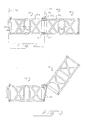
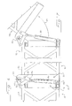
- Figures 2 and 6 show the crash attenuator 10 in a deployed position.
- Each of the bays 12, 18 defines a respective longitudinal axis 66, 68 ( Figure 2), and in the deployed position of Figure 2 the longitudinal axes 66, 68 are substantially parallel to one another and oriented substantially horizontally (i.e. parallel to the roadway supporting the truck).
- the reference symbol 64 designates a rotation angle that will be used as a measure of the rotational position of the second bay 18 with respect to the first bay 12 about the rotational axis 42.
- the rotation angle 64 takes the value of 0°.
- the reference symbol 70 designates a vertical plane passing through the mounting arrangement 30 forward of the first bay 12, and both the first and second bays 12, 18 are disposed entirely rearwardly of the vertical plane 70 when the crash attenuator 10 is in the deployed position of Figure 2.
- the reference symbol 72 is used to indicate a plane passing through the rotational axis 42 and oriented transversely to the longitudinal axis 66.
- Figures 3 and 7 show a side view corresponding to that of Figure 2, in which the actuator 50 has been extended partially to raise the second bay 18.
- the angle 64 is about 55°. This represents an intermediate stage in the retraction of the second bay 18.
- Figures 4 and 8 show the crash attenuator 10 at another, more advanced stage in the retraction of the second bay 18.
- the actuator 50 has been extended until the rotation angle 64 is about 120° ( Figure 8). Note that in this position, the lower edge 28 has moved forwardly of the plane 72 ( Figure 4).
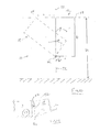
- the second bay 18 is characterized by a depth a and a length b.
- the partially-retracted attenuator has a height h. Further rotation has the effect of lifting the lower edge 28 until the lower edge 28 crosses the plane 72, after which the lower edge 28 begins to move downwardly.
- the height of the lower edge 28 (and therefore the overall height of the attenuator 10) becomes less than h.
- the angle ⁇ /2 of Figure 10 is equal to arctan (a/b), and the angle ⁇ is equal to 2 arctan (a/b).
- the second bay 18 be rotated by an angle no less than (90 + 2 arctan (a/b)) in the retracted position in order to ensure that the overall height of the fully retracted attenuator 10 is less than that of an attenuator in which the second bay 18 is rotated by 90° between the deployed and the retracted positions.
- (a/b) is equal to 0.5 and the second bay 18 is preferably rotated by a rotation angle no less than 143° between the deployed and the retracted positions. Further retraction of the second bay 18 beyond 143° reduces the overall height of the crash attenuator 10.
- Attenuator bays with a rectangular shape
- the present invention can be applied to attenuator bays of many other cross-sectional shapes, such as ellipsoidal, polygonal, and other shapes.
- Figures 5 and 9 show the crash attenuator 10 in the fully retracted position, in which the actuator 50 has been extended to the point where the rotation angle 64 is approximately equal to 180° (Figure 9).
- the lower edge 28 is positioned substantially forwardly of the plane 72, on the same side of the plane 72 as the front end 14 of the first bay 12 ( Figure 5).
- the back end 22 of the second bay 18 is positioned adjacent to and overlying the front end 14 of the first bay 12, and the upper portions 24, 26 face one another.
- the first upper portion 24 continues to face upwardly (since it has not been rotated from the position of Figures 1 and 2), and the second upper portion 26 now faces downwardly, toward the first bay 12.
- the second bay 18 rests upon and is supported by the first bay 12. Also, both of the first and second bays 12, 18 are still located entirely behind the vertical plane 70.
- the second bay 18 can be moved with the actuator 50 from the retracted position of Figures 5 and 9 to the deployed position of Figures 1, 2 and 6 for use.
- the second bay 18 is rotated by about 180° with respect to the first bay 12 in the retracted position of Figures 5 and 9 as compared to the deployed position of Figures 2 and 6.
- the second bay 18 is not rotated to such a large extent.
- the second bay 18 may be rotated by 145°, 155°, 165° or 175" with respect to the first bay 12.
- the second bay 18 may be rotated by more than 180°, if the rotational axis is positioned such that the back end 22 is lower than the front end 20 in the retracted position. In all cases the second bay is rotated by more than 90° between the deployed and retracted positions.
- rotation angles greater than 145° provide the advantage of reducing the overall height of the folded crash attenuator as compared to a folded crash attenuator of the same dimensions that is folded only by a rotation angle of 90° (as in the prior art discussed above).
- the second bay 18 in the retracted position is preferably rotated by a rotation angle 64 greater than 145°, more preferably greater than 165°, and most preferably about 180°.
- the rotation angle 64 may be greater than 180°. Note that the second bay 18 extends forwardly of the plane 72 for all values of the rotation angle 64 greater than 90°.
- the crash attenuator can include more than two bays, and the bays themselves may vary widely in construction.
- bays of the type described in the following U.S. Patents can all be adapted for use with this invention: June U.S. Pat. 5,642,792 , Gertz U.S. Pat. 5,248,129 , Gertz U.S. Pat. 5,199,577 , Krage U.S. Pat. 4,711,481 , Fritton U.S. Pat. 4,635,981 , Walker U.S. Pat. 4,008,915 .
- other types of hinges, actuators and linkages can be substituted for the illustrated elements.
- the actuator can include cable extending between the second bay and the truck and some means such as a winch or the like for pulling the cables to rotate the second bay to the retracted position.
- the retracted position may leave the second bay somewhat angled with respect to the underlying first bay, rather than in the overlying substantially, parallel position shown in the drawings.
- the fully deployed position is characterized by a rotation angle of 170° or 175°, this may reduce the strain on the linkage and the actuator.
- the system is designed such that there is no load on the actuators or the links when the second bay is in either the deployed or the fully retracted position.
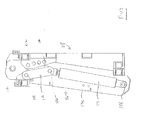
- the Figures 11-13 show selected components of a best mode example.
- the illustrated components of Figures 11 and 12 include a frame 116 that forms the back end of the first bay and a frame 118 that forms the front end of the second bay.
- the frames 116, 118 are rotatably interconnected by a rotational joint 100, and the position of the frame 118 (and therefore the second bay) is determined by actuators, which in this example take the form of hydraulic cylinders 114.
- actuators which in this example take the form of hydraulic cylinders 114.
- the upper end of the rod of each hydraulic cylinder 114 is connected by a first link 110 to the frame 116 and by a second link 112 to the frame 118.
- Figure 12 shows the manner in which the frame 116 includes a pair of vertically oriented, spaced, parallel plates 120 disposed on opposite sides of each of the hydraulic cylinders 114.
- the frame 118 includes a pair of vertically oriented, spaced, parallel plates 122, each disposed outwardly of a respective one of the plates 120.
- each hydraulic cylinder 114 is at least partially received between the respective plates 120.
- the hydraulic cylinders 114 move the second frame 118 to the deployed position, the hydraulic cylinders 114 are received between and protected by the respective plates 120. In this way, the hydraulic cylinders114 are protected from damage from low velocity impacts, or from casual damage, for example in a highway work zone.
- the energy absorbing elements of the first and second bays 12, 18 can be constructed as described for example in U.S. Patents 6,092,959 and 5,199,755 , assigned to the Assignee of the present invention and hereby incorporated by reference, and the material used to form individual cells can for example be sheet aluminum.
- the actuator is a welded hydraulic cylinder (welded body) as opposed to a tie rod type hydraulic cylinder, because a welded cylinder has a smaller profile with smaller outside dimensions and is therefore more easily packaged.
- a tie rod type cylinder can be used in alternative embodiments.
- Table 1 Presently Preferred Crash Alternator Parameters A. Mass of Frame Elements (kg) Transverse frame at back end 16 72 Transverse frame at front end 20 82 Transverse frame at back end 22 152 Side frame element 32 B. Moment of Inertia of Side Frame Elements (kg-m 2 ) 1.92
- each bay is provided with upper and lower tie rods that extend across the bay (over and under the respective energy absorbing element 16, respectively).
- Each tie rod is anchored at each end to a side frame element 34 near the respective pin 56, and each tie rod includes two overlapping parts held together by one or more shear pins such as bolts. A force tending to collapse a bay places the tie rods of the bay in tension, and the shear pins are designed to fail at a selected tensile load on the tie rod.
- the hinges 34 on both sides of the bay are free to open, and the crash cushion operates as described in U.S. Patent 6,092,959 .
- the main advantage of the tie rods described above is that they ensure that the hinges on both sides of a bay begin to rotate at the same time during a collision.
- the crash attenuator 10 provides important advantages. In the fully retracted position of Figure 5 the attenuator is short in length (measured horizontally from the truck T of Figure 1) as well as in height (measured vertically from the roadway that supports the truck T of Figure 1). This arrangement facilitates over the road transport of the raised crash attenuator 10, and it presents fewer height restrictions to movement of the truck T, even when the crash attenuator 10 is fully retracted.
- position is intended broadly to encompass a range of positions.
- front or “forward” are intended to mean closer to the vehicle on which a crash attenuator is mounted, and the terms “back” or “rear” are intended to mean farther away from the vehicle on which the crash attenuator is mounted.
Landscapes
- Engineering & Computer Science (AREA)
- Mechanical Engineering (AREA)
- Vibration Dampers (AREA)
- Aiming, Guidance, Guns With A Light Source, Armor, Camouflage, And Targets (AREA)
- Refuge Islands, Traffic Blockers, Or Guard Fence (AREA)
- Fluid-Damping Devices (AREA)
Claims (20)
- Amortisseur de collision (10) monté sur véhicule comprenant : une première nacelle (12) comprenant une extrémité avant (14) conçue pour être montée sur un véhicule et une extrémité arrière (16) écartée de ladite extrémité avant (14) dans une direction longitudinale, et une seconde nacelle (18) comprenant une extrémité avant (20) et une extrémité arrière (22) écartée de ladite extrémité avant (20) dans une direction longitudinale, ladite extrémité avant (20) de ladite seconde nacelle (18) étant reliée de façon pivotante à ladite extrémité arrière (16) de ladite première nacelle (12), dans lequel ladite première nacelle (12) présente une orientation sensiblement horizontale, caractérisé en ce que la seconde nacelle (18) peut être pivotée par rapport à ladite première nacelle (12) entre une position déployée, dans laquelle ladite seconde nacelle (18) présente une orientation sensiblement horizontale, et une position rentrée, dans laquelle ladite seconde nacelle (18) est tournée par rapport à ladite première nacelle (12) d'un angle de rotation (64) supérieur à 90° par rapport à ladite position déployée lorsque ladite première nacelle (12) est maintenue dans ladite orientation sensiblement horizontale, où il existe un actionneur (50) accouplé à la seconde nacelle (18) pour déplacer la seconde nacelle (18) entre la position déployée et la position rentrée.
- Amortisseur de collision (10) monté sur véhicule selon la revendication 1,
dans lequel lesdites première et seconde nacelles (12, 18) présentent chacune une surface supérieure (24, 26), où au moins une partie de ladite surface supérieure (26) de ladite seconde nacelle (18) recouvre, et fait face à, au moins une partie de ladite surface supérieure (24) de ladite première nacelle (12) lorsque ladite seconde nacelle (18) se trouve dans ladite position rentrée. - Amortisseur de collision (10) monté sur véhicule selon la revendication 1 ou la revendication 2, dans lequel ledit angle de rotation (64) est d'environ 180°.
- Amortisseur de collision (10) monté sur véhicule selon l'une quelconque des revendications 1, 2 ou 3, dans lequel lesdites première et seconde nacelles (12, 18) comprennent respectivement des première et seconde structures de châssis.
- Amortisseur de collision monté sur véhicule (10) selon la revendication 4, dans lequel lesdites première et seconde nacelles (12, 18) comprennent des premier et second éléments d'absorption d'énergie disposés dans lesdites première et seconde structures de châssis respectivement.
- Amortisseur de collision (10) monté sur véhicule selon l'une quelconque des revendications précédentes, dans lequel
ledit actionneur (50) comprend en outre des premier et second pivots (52, 54), dans lequel ledit premier pivot (52) est couplé à ladite extrémité arrière (16) de ladite première nacelle (12), dans lequel ledit second pivot (54) est couplé à ladite extrémité arrière (16) de ladite première nacelle (12) par une première liaison (56), et dans lequel le second pivot (54) est couplé à ladite extrémité avant (20) de ladite seconde nacelle (18) par une seconde liaison (58). - Amortisseur de collision (10) monté sur véhicule selon la revendication 6, dans lequel ledit actionneur (50) comprend un vérin hydraulique s'étendant entre les premier et second pivots (52, 54).
- Amortisseur de collision (10) monté sur véhicule selon l'une quelconque des revendications précédentes, dans lequel ledit angle de rotation (64) comprend un premier angle de rotation, et dans lequel ladite extrémité arrière (22) de ladite seconde nacelle (18) comprend un bord inférieur (28), où ledit bord inférieur (28) est positionné à une hauteur h lorsque ladite seconde nacelle est tournée par rapport à ladite première nacelle (12) d'un second angle de rotation d'environ 90°, et où ledit premier angle de rotation est sélectionné de telle sorte que dans la position rentrée, ledit bord inférieur (28) est positionné à une hauteur qui n'est pas supérieure à la hauteur h.
- Amortisseur de collision (10) monté sur véhicule selon l'une quelconque des revendications précédentes, dans lequel ladite première nacelle (12) demeure dans ladite orientation sensiblement horizontale lorsque ladite seconde nacelle (18) est tournée entre lesdites positions déployée et rentrée.
- Amortisseur de collision (10) monté sur véhicule selon l'une quelconque des revendications précédentes, dans lequel ladite seconde nacelle (18) peut être pivotée par rapport à ladite première nacelle (12) autour d'un axe de rotation.
- Amortisseur de collision (10) monté sur véhicule selon la revendication 1, dans lequel ladite extrémité arrière (22) de ladite seconde nacelle (18) comprend un bord inférieur (28), où ladite première nacelle (12) définit un plan croisant de façon perpendiculaire un axe longitudinal (66) s'étendant entre ladite extrémité avant (14) et ladite extrémité arrière (16) de ladite première nacelle, et où l'angle de rotation (64) est suffisamment supérieur à 90° de telle sorte que, lorsque ladite seconde nacelle (18) se trouve à la position rentrée, le bord inférieur (28) est positionné du même côté du plan que ladite extrémité avant (14) de ladite première nacelle (12).
- Amortisseur de collision (10) monté sur véhicule selon l'une quelconque des revendications précédentes, dans lequel ledit angle de rotation (64) est supérieur à 125°.
- Amortisseur de collision (10) monté sur véhicule selon l'une quelconque des revendications précédentes, dans lequel ledit angle de rotation (64) est supérieur à 145°.
- Amortisseur de collision (10) monté sur véhicule selon l'une quelconque des revendications précédentes, dans lequel ledit angle de rotation (64) est supérieur à 165°.
- Amortisseur de collision monté sur véhicule (10) selon l'une quelconque des revendications précédentes, dans lequel ledit angle de rotation (64) est supérieur à 180°.
- Amortisseur de collision monté sur véhicule (10) selon l'une quelconque des revendications précédentes, comprenant en outre un agencement de montage (30) fixé à ladite extrémité avant (14) de ladite première nacelle (12), dans lequel ledit agencement de montage (30) supporte une rotation de ladite première nacelle (12) autour d'un axe sensiblement horizontal (90) de façon adjacente à ladite extrémité avant (14) de celle-ci.
- Amortisseur de collision (10) monté sur véhicule selon la revendication 1, dans lequel ladite extrémité avant (20) de ladite seconde nacelle (18) est positionnée de façon adjacente à ladite extrémité arrière (16) de ladite première nacelle (12), et ladite extrémité arrière (22) de ladite seconde nacelle (18) est positionnée de façon adjacente à ladite extrémité avant (14) de ladite première nacelle (12) lorsque ladite seconde nacelle (18) se trouve dans ladite position rentrée.
- Amortisseur de collision (10) monté sur véhicule selon la revendication 17, dans lequel ladite seconde nacelle (18) demeure sur ladite première nacelle (12) lorsque ladite seconde nacelle (18) se trouve dans ladite position rentrée.
- Amortisseur de collision (10) monté sur véhicule selon l'une quelconque des revendications précédentes, dans lequel ladite seconde nacelle (18) est tournée par rapport à ladite première nacelle (12), par l'intermédiaire d'un angle de rotation (64) supérieur à 90° par rapport à ladite orientation sensiblement horizontale de ladite seconde nacelle (18), lorsque ledit amortisseur de collision (10) monté sur véhicule se trouve dans ladite configuration rentrée, où ladite extrémité avant (20) de ladite seconde nacelle (18) est positionnée de façon adjacente à ladite extrémité arrière (16) de ladite première nacelle (12), et ladite extrémité arrière (22) de ladite seconde nacelle (18) est positionnée de façon adjacente à ladite extrémité avant de ladite première nacelle (12) lorsque ledit amortisseur de collision (10) monté sur véhicule se trouve dans ladite position rentrée.
- Véhicule pouvant être conduit sur une route doté d'un amortisseur de collision (10) monté sur véhicule selon l'une quelconque des revendications précédentes, dans lequel le véhicule comprend une extrémité arrière à laquelle l'extrémité avant (14) de la première nacelle (12) est fixée, où ladite première nacelle (12) de l'amortisseur de collision (10) présente une partie supérieure et une partie inférieure, où ladite partie inférieure est espacée au-dessus de la route lorsque ledit amortisseur de collision (10) monté sur véhicule se trouve dans lesdites configurations rentrée et déployée.
Applications Claiming Priority (5)
| Application Number | Priority Date | Filing Date | Title |
|---|---|---|---|
| US2833 | 1995-08-25 | ||
| US32572901P | 2001-09-28 | 2001-09-28 | |
| US325729P | 2001-09-28 | ||
| US10/002,833 US20030077119A1 (en) | 2001-09-28 | 2001-11-01 | Vehicle mounted crash attenuator |
| PCT/US2002/027863 WO2003029686A2 (fr) | 2001-09-28 | 2002-09-03 | Amortisseur de choc monte sur un vehicule |
Publications (3)
| Publication Number | Publication Date |
|---|---|
| EP1436465A2 EP1436465A2 (fr) | 2004-07-14 |
| EP1436465A4 EP1436465A4 (fr) | 2005-07-13 |
| EP1436465B1 true EP1436465B1 (fr) | 2007-08-15 |
Family
ID=26670945
Family Applications (1)
| Application Number | Title | Priority Date | Filing Date |
|---|---|---|---|
| EP02766205A Expired - Lifetime EP1436465B1 (fr) | 2001-09-28 | 2002-09-03 | Amortisseur de choc monte sur un vehicule |
Country Status (10)
| Country | Link |
|---|---|
| US (2) | US20030077119A1 (fr) |
| EP (1) | EP1436465B1 (fr) |
| CN (1) | CN1596328A (fr) |
| AR (1) | AR036641A1 (fr) |
| AT (1) | ATE370277T1 (fr) |
| AU (1) | AU2002329948B2 (fr) |
| DE (1) | DE60221867D1 (fr) |
| NZ (1) | NZ532481A (fr) |
| TW (1) | TW568848B (fr) |
| WO (1) | WO2003029686A2 (fr) |
Families Citing this family (22)
| Publication number | Priority date | Publication date | Assignee | Title |
|---|---|---|---|---|
| US7243964B1 (en) * | 1999-04-28 | 2007-07-17 | Traffix Devices, Inc | Truck mounted crash attenuator |
| US6581992B1 (en) | 1999-04-28 | 2003-06-24 | Traffix Devices, Inc. | Truck mounted crash attenuator |
| JP2006523577A (ja) * | 2003-04-17 | 2006-10-19 | エナジー アブソープション システムズ, インク. | トラック取付用緩衝装置のための取付具 |
| US7874572B2 (en) | 2005-01-10 | 2011-01-25 | Energy Absorption Systems, Inc. | Towable impact attenuator |
| EP1695874A1 (fr) * | 2005-02-25 | 2006-08-30 | Albert W. Unrath, Inc. | Coussin pour un système d'attenuation de collision |
| US7802829B2 (en) | 2007-01-30 | 2010-09-28 | Traffix Devices, Inc. | Trailer mounted crash attenuator |
| US7699347B2 (en) * | 2007-08-27 | 2010-04-20 | Shoap Stephen D | Method and apparatus for a shared crumple zone |
| US7931317B2 (en) | 2008-03-11 | 2011-04-26 | Kern Charles L | Reusable trailer mounted attenuator |
| US8113554B2 (en) * | 2008-10-30 | 2012-02-14 | Shoap Stephen D | Method and apparatus for an attachable and removable crumple zone |
| SG11201601724TA (en) | 2013-09-11 | 2016-04-28 | Energy Absorption System | Crash attenuator |
| KR101614601B1 (ko) * | 2014-05-09 | 2016-04-21 | 김영훈 | 차량 충격흡수장치 |
| US10319227B2 (en) | 2015-06-29 | 2019-06-11 | Royal Truck & Equipment, Inc. | Roadway work area safety truck |
| US11008717B2 (en) | 2015-06-29 | 2021-05-18 | Royal Truck & Equipment, Inc. | Safety truck attachments, and methods of safety truck use |
| US10995462B2 (en) | 2018-10-10 | 2021-05-04 | International Business Machines Corporation | Autonomous mobile attenuator system |
| CN111208811B (zh) * | 2018-11-22 | 2024-06-21 | 北京奇虎科技有限公司 | 扫地机器人的窄缝脱困方法、装置、设备及可读存储介质 |
| WO2020231651A1 (fr) | 2019-05-15 | 2020-11-19 | Trinity Highway Products Llc | Atténuateur de collision avec ensemble charnière de plaque de dégagement, ensemble charnière de plaque de dégagement et son procédé d'utilisation |
| CN110466464A (zh) * | 2019-08-20 | 2019-11-19 | 中山市易路美道路养护科技有限公司 | 带有缓冲防撞柱的防撞装置 |
| AU2021265111B2 (en) | 2020-05-01 | 2025-12-04 | Traffix Devices, Inc. | Vehicle-mounted crash attenuator |
| US11948477B2 (en) | 2021-07-29 | 2024-04-02 | Concaten, Inc. | Emergency response barrier |
| WO2023009725A1 (fr) * | 2021-07-29 | 2023-02-02 | Concaten, Inc. | Barrière de réponse d'urgence |
| PL447560A1 (pl) * | 2024-01-22 | 2025-07-28 | Krzyżoś Mateusz Przedsiębiorstwo Produkcyjno Handlowe Strobos | Amortyzator zderzeniowy |
| US20260009193A1 (en) * | 2024-07-02 | 2026-01-08 | Lindsay Transportation Solutions, Llc | Vehicle-mounted attenuator |
Family Cites Families (50)
| Publication number | Priority date | Publication date | Assignee | Title |
|---|---|---|---|---|
| US3506295A (en) * | 1968-10-14 | 1970-04-14 | Msl Ind Inc | Shock absorber bumper |
| US3674115A (en) * | 1970-09-23 | 1972-07-04 | Energy Absorption System | Liquid shock absorbing buffer |
| US3757562A (en) * | 1971-10-20 | 1973-09-11 | Budd Co | Method of impact testing a metallic structure |
| GB1405771A (en) * | 1972-07-07 | 1975-09-10 | Grindstedvaerket As | Production and use of proteolytic enzymes |
| JPS5422866Y2 (fr) | 1973-08-24 | 1979-08-08 | ||
| US3944187A (en) * | 1974-09-13 | 1976-03-16 | Dynamics Research And Manufacturing, Inc. | Roadway impact attenuator |
| US3972390A (en) * | 1975-03-05 | 1976-08-03 | Programmed & Remote Systems Corporation | Energy absorbing device |
| US4008915A (en) * | 1975-06-04 | 1977-02-22 | Dynamics Research And Manufacturing, Inc. | Impact barrier for vehicles |
| US4227593A (en) * | 1976-10-04 | 1980-10-14 | H. H. Robertson Company | Kinetic energy absorbing pad |
| US4221413A (en) * | 1978-02-28 | 1980-09-09 | Yves Bonnetain | Shock absorption bumper for an automotive vehicle |
| US4190275A (en) * | 1978-03-16 | 1980-02-26 | Fibco Inc. | Impact attenuator |
| US4204659A (en) * | 1978-04-25 | 1980-05-27 | The United States Of America As Represented By The Secretary Of The Navy | Energy absorber |
| AU5840580A (en) * | 1979-05-19 | 1980-11-27 | Kunert, H. | Windscreen |
| US4352484A (en) * | 1980-09-05 | 1982-10-05 | Energy Absorption Systems, Inc. | Shear action and compression energy absorber |
| US4413856A (en) * | 1981-08-07 | 1983-11-08 | General Motors Corporation | Hardbar energy absorbing bumper system for vehicles |
| US4407484A (en) * | 1981-11-16 | 1983-10-04 | Meinco Mfg. Co. | Impact energy absorber |
| US4452431A (en) * | 1982-05-19 | 1984-06-05 | Energy Absorption Systems, Inc. | Restorable fender panel |
| US4674911A (en) * | 1984-06-13 | 1987-06-23 | Energy Absorption Systems, Inc. | Energy absorbing pneumatic crash cushion |
| US4635981A (en) * | 1984-10-29 | 1987-01-13 | Energy Absorption Systems, Inc. | Impact attenuating body |
| US4770420A (en) * | 1985-01-14 | 1988-09-13 | United Research And Manufacturing, Inc. | Vehicle mounting system for impact absorption apparatus |
| US4658941A (en) * | 1985-01-14 | 1987-04-21 | Hexcel Corporation | Vehicle mounting system for impact absorption apparatus |
| US4711481A (en) * | 1985-10-25 | 1987-12-08 | Energy Absorption Systems, Inc. | Vehicle impact attenuating device |
| US4655434A (en) | 1986-04-24 | 1987-04-07 | Southwest Research Institute | Energy absorbing guardrail terminal |
| US5052732A (en) * | 1990-04-02 | 1991-10-01 | Renco Supply, Inc. | Crash attenuator utilizing fibrous honeycomb material |
| US5123775A (en) * | 1990-12-31 | 1992-06-23 | Graham-Migletz Enterprises, Inc. | Aluminum can truck-mounted attenuator |
| US5199755A (en) * | 1991-04-03 | 1993-04-06 | Energy Absorption Systems, Inc. | Vehicle impact attenuating device |
| US5403113A (en) * | 1992-08-12 | 1995-04-04 | Energy Absorption Systems, Inc. | Shear loading energy absorbing device |
| US5248129A (en) * | 1992-08-12 | 1993-09-28 | Energy Absorption Systems, Inc. | Energy absorbing roadside crash barrier |
| EP0660787B1 (fr) | 1992-09-02 | 2000-05-10 | Vanderbilt University | Dispositif d'amortissement de chocs |
| US5403112A (en) * | 1993-09-08 | 1995-04-04 | Vanderbilt University | Crash impact attenuator constructed from high molecular weight/high density polyethylene |
| GB2286160A (en) | 1994-02-04 | 1995-08-09 | Aph Road Safety Ltd | Vehicle crash cushion |
| US5494371A (en) * | 1994-11-14 | 1996-02-27 | Energy Absorption Systems, Inc. | Crash attenuator |
| US5551796A (en) * | 1995-01-20 | 1996-09-03 | Emergency Public Safety Services, L.L.C. | Moveable barrier |
| US5733062A (en) * | 1995-11-13 | 1998-03-31 | Energy Absorption Systems, Inc. | Highway crash cushion and components thereof |
| US5697657A (en) * | 1996-01-11 | 1997-12-16 | Albert W. Unrath, Inc. | Vehicle mounted crash attenuation system |
| US5642792A (en) * | 1996-03-12 | 1997-07-01 | Energy Absorption Systems, Inc. | Highway crash cushion |
| US5947452A (en) * | 1996-06-10 | 1999-09-07 | Exodyne Technologies, Inc. | Energy absorbing crash cushion |
| US5823584A (en) * | 1996-10-08 | 1998-10-20 | Vanderbilt University | Vehicle mounted crash impact attenuator |
| US5799755A (en) * | 1996-11-14 | 1998-09-01 | Otis Elevator Company | Linear motor transfer of cab horizontally between elevator and bogey platforms |
| US5851005A (en) * | 1997-04-15 | 1998-12-22 | Muller; Franz M. | Energy absorption apparatus |
| US6024341A (en) * | 1997-05-05 | 2000-02-15 | Traffix Devices, Inc. | Crash attenuator of compressible sections |
| US6116805A (en) * | 1997-05-05 | 2000-09-12 | Gertz; David C. | Crash attenuator with a row of compressible hoops |
| US5797592A (en) * | 1997-06-16 | 1998-08-25 | Energy Absorption Systems, Inc. | Roadside energy absorbing barrier with improved fender panel fastener |
| US6203079B1 (en) * | 1997-11-24 | 2001-03-20 | Automotive Technologies International, Inc. | Damped crash attenuator |
| US6098767A (en) * | 1997-12-15 | 2000-08-08 | Albert W. Unrath, Inc. | Cushion for crash attenuation system |
| US6186565B1 (en) * | 1998-10-28 | 2001-02-13 | Albert W. Unrath | Lift apparatus for attenuator cushion |
| US6092959A (en) * | 1998-11-16 | 2000-07-25 | Energy Absorption Systems, Inc. | Method for decelerating a vehicle, highway crash cushion, and energy absorbing element therefor |
| US6183042B1 (en) * | 1998-12-21 | 2001-02-06 | Albert W. Unrath | Mobile apparatus for securely retrieving and placing markers on a surface and method therefor |
| US6581992B1 (en) * | 1999-04-28 | 2003-06-24 | Traffix Devices, Inc. | Truck mounted crash attenuator |
| US6244637B1 (en) * | 2000-03-02 | 2001-06-12 | Energy Absorption Systems, Inc. | Adjustable tailgate mount for truck mounted attenuator |
-
2001
- 2001-11-01 US US10/002,833 patent/US20030077119A1/en not_active Abandoned
-
2002
- 2002-09-03 CN CN02823821.4A patent/CN1596328A/zh active Pending
- 2002-09-03 AT AT02766205T patent/ATE370277T1/de not_active IP Right Cessation
- 2002-09-03 WO PCT/US2002/027863 patent/WO2003029686A2/fr not_active Ceased
- 2002-09-03 AU AU2002329948A patent/AU2002329948B2/en not_active Ceased
- 2002-09-03 DE DE60221867T patent/DE60221867D1/de not_active Expired - Lifetime
- 2002-09-03 NZ NZ532481A patent/NZ532481A/en unknown
- 2002-09-03 EP EP02766205A patent/EP1436465B1/fr not_active Expired - Lifetime
- 2002-09-13 TW TW091121040A patent/TW568848B/zh not_active IP Right Cessation
- 2002-09-26 AR ARP020103639A patent/AR036641A1/es unknown
-
2003
- 2003-07-28 US US10/628,319 patent/US6905282B2/en not_active Expired - Lifetime
Also Published As
| Publication number | Publication date |
|---|---|
| WO2003029686A3 (fr) | 2003-12-31 |
| WO2003029686A2 (fr) | 2003-04-10 |
| EP1436465A4 (fr) | 2005-07-13 |
| ATE370277T1 (de) | 2007-09-15 |
| EP1436465A2 (fr) | 2004-07-14 |
| US20040145173A1 (en) | 2004-07-29 |
| NZ532481A (en) | 2007-02-23 |
| AU2002329948B2 (en) | 2007-04-26 |
| US6905282B2 (en) | 2005-06-14 |
| US20030077119A1 (en) | 2003-04-24 |
| CN1596328A (zh) | 2005-03-16 |
| AR036641A1 (es) | 2004-09-22 |
| DE60221867D1 (de) | 2007-09-27 |
| TW568848B (en) | 2004-01-01 |
Similar Documents
| Publication | Publication Date | Title |
|---|---|---|
| US6905282B2 (en) | Vehicle mounted crash attenuator | |
| AU2002329948A1 (en) | Vehicle Mounted Crash Attenuator | |
| US6581992B1 (en) | Truck mounted crash attenuator | |
| US5507546A (en) | Underride protection bumper | |
| EP0795440B1 (fr) | Amortisseur de chocs pour routes | |
| US7497508B2 (en) | Bonnet for a vehicle | |
| US6799783B2 (en) | Arrangement for underrun protection in vehicles | |
| US20230331179A1 (en) | Vehicle-mounted crash attenuator | |
| US6186565B1 (en) | Lift apparatus for attenuator cushion | |
| US7243964B1 (en) | Truck mounted crash attenuator | |
| CN114802069A (zh) | 一种可翻转防撞装置及自卸车辆 | |
| US20260009193A1 (en) | Vehicle-mounted attenuator | |
| US20260009194A1 (en) | Vehicle-mounted attenuator | |
| WO2004083526A1 (fr) | Garniture de securite | |
| US20260009192A1 (en) | Vehicle-mounted attenuator | |
| HK1073342A (en) | Vehicle mounted crash attenuator | |
| DE20023228U1 (de) | Fronthaubenanordnung |
Legal Events
| Date | Code | Title | Description |
|---|---|---|---|
| PUAI | Public reference made under article 153(3) epc to a published international application that has entered the european phase |
Free format text: ORIGINAL CODE: 0009012 |
|
| 17P | Request for examination filed |
Effective date: 20040420 |
|
| AK | Designated contracting states |
Kind code of ref document: A2 Designated state(s): AT BE BG CH CY CZ DE DK EE ES FI FR GB GR IE IT LI LU MC NL PT SE SK TR |
|
| AX | Request for extension of the european patent |
Extension state: AL LT LV MK RO SI |
|
| RIN1 | Information on inventor provided before grant (corrected) |
Inventor name: PORTERFIELD, ANDREW, A. Inventor name: LEONHARDT, PATRICK, A. |
|
| REG | Reference to a national code |
Ref country code: HK Ref legal event code: DE Ref document number: 1067392 Country of ref document: HK |
|
| A4 | Supplementary search report drawn up and despatched |
Effective date: 20050530 |
|
| RIC1 | Information provided on ipc code assigned before grant |
Ipc: 7B 60R 19/00 B Ipc: 7E 01F 15/00 A |
|
| 17Q | First examination report despatched |
Effective date: 20060224 |
|
| GRAP | Despatch of communication of intention to grant a patent |
Free format text: ORIGINAL CODE: EPIDOSNIGR1 |
|
| GRAS | Grant fee paid |
Free format text: ORIGINAL CODE: EPIDOSNIGR3 |
|
| GRAA | (expected) grant |
Free format text: ORIGINAL CODE: 0009210 |
|
| AK | Designated contracting states |
Kind code of ref document: B1 Designated state(s): AT BE BG CH CY CZ DE DK EE ES FI FR GB GR IE IT LI LU MC NL PT SE SK TR |
|
| REG | Reference to a national code |
Ref country code: GB Ref legal event code: FG4D |
|
| REG | Reference to a national code |
Ref country code: CH Ref legal event code: EP |
|
| REG | Reference to a national code |
Ref country code: IE Ref legal event code: FG4D |
|
| REF | Corresponds to: |
Ref document number: 60221867 Country of ref document: DE Date of ref document: 20070927 Kind code of ref document: P |
|
| PG25 | Lapsed in a contracting state [announced via postgrant information from national office to epo] |
Ref country code: BG Free format text: LAPSE BECAUSE OF FAILURE TO SUBMIT A TRANSLATION OF THE DESCRIPTION OR TO PAY THE FEE WITHIN THE PRESCRIBED TIME-LIMIT Effective date: 20071115 Ref country code: NL Free format text: LAPSE BECAUSE OF FAILURE TO SUBMIT A TRANSLATION OF THE DESCRIPTION OR TO PAY THE FEE WITHIN THE PRESCRIBED TIME-LIMIT Effective date: 20070815 Ref country code: ES Free format text: LAPSE BECAUSE OF FAILURE TO SUBMIT A TRANSLATION OF THE DESCRIPTION OR TO PAY THE FEE WITHIN THE PRESCRIBED TIME-LIMIT Effective date: 20071126 Ref country code: FI Free format text: LAPSE BECAUSE OF FAILURE TO SUBMIT A TRANSLATION OF THE DESCRIPTION OR TO PAY THE FEE WITHIN THE PRESCRIBED TIME-LIMIT Effective date: 20070815 |
|
| NLV1 | Nl: lapsed or annulled due to failure to fulfill the requirements of art. 29p and 29m of the patents act | ||
| PG25 | Lapsed in a contracting state [announced via postgrant information from national office to epo] |
Ref country code: AT Free format text: LAPSE BECAUSE OF FAILURE TO SUBMIT A TRANSLATION OF THE DESCRIPTION OR TO PAY THE FEE WITHIN THE PRESCRIBED TIME-LIMIT Effective date: 20070815 Ref country code: CH Free format text: LAPSE BECAUSE OF FAILURE TO SUBMIT A TRANSLATION OF THE DESCRIPTION OR TO PAY THE FEE WITHIN THE PRESCRIBED TIME-LIMIT Effective date: 20070815 Ref country code: LI Free format text: LAPSE BECAUSE OF FAILURE TO SUBMIT A TRANSLATION OF THE DESCRIPTION OR TO PAY THE FEE WITHIN THE PRESCRIBED TIME-LIMIT Effective date: 20070815 |
|
| REG | Reference to a national code |
Ref country code: CH Ref legal event code: PL |
|
| PG25 | Lapsed in a contracting state [announced via postgrant information from national office to epo] |
Ref country code: BE Free format text: LAPSE BECAUSE OF FAILURE TO SUBMIT A TRANSLATION OF THE DESCRIPTION OR TO PAY THE FEE WITHIN THE PRESCRIBED TIME-LIMIT Effective date: 20070815 |
|
| EN | Fr: translation not filed | ||
| PG25 | Lapsed in a contracting state [announced via postgrant information from national office to epo] |
Ref country code: MC Free format text: LAPSE BECAUSE OF NON-PAYMENT OF DUE FEES Effective date: 20070930 Ref country code: DE Free format text: LAPSE BECAUSE OF FAILURE TO SUBMIT A TRANSLATION OF THE DESCRIPTION OR TO PAY THE FEE WITHIN THE PRESCRIBED TIME-LIMIT Effective date: 20071117 Ref country code: GR Free format text: LAPSE BECAUSE OF FAILURE TO SUBMIT A TRANSLATION OF THE DESCRIPTION OR TO PAY THE FEE WITHIN THE PRESCRIBED TIME-LIMIT Effective date: 20071116 Ref country code: DK Free format text: LAPSE BECAUSE OF FAILURE TO SUBMIT A TRANSLATION OF THE DESCRIPTION OR TO PAY THE FEE WITHIN THE PRESCRIBED TIME-LIMIT Effective date: 20070815 |
|
| PG25 | Lapsed in a contracting state [announced via postgrant information from national office to epo] |
Ref country code: SK Free format text: LAPSE BECAUSE OF FAILURE TO SUBMIT A TRANSLATION OF THE DESCRIPTION OR TO PAY THE FEE WITHIN THE PRESCRIBED TIME-LIMIT Effective date: 20070815 Ref country code: PT Free format text: LAPSE BECAUSE OF FAILURE TO SUBMIT A TRANSLATION OF THE DESCRIPTION OR TO PAY THE FEE WITHIN THE PRESCRIBED TIME-LIMIT Effective date: 20080115 Ref country code: CZ Free format text: LAPSE BECAUSE OF FAILURE TO SUBMIT A TRANSLATION OF THE DESCRIPTION OR TO PAY THE FEE WITHIN THE PRESCRIBED TIME-LIMIT Effective date: 20070815 |
|
| PLBE | No opposition filed within time limit |
Free format text: ORIGINAL CODE: 0009261 |
|
| STAA | Information on the status of an ep patent application or granted ep patent |
Free format text: STATUS: NO OPPOSITION FILED WITHIN TIME LIMIT |
|
| PG25 | Lapsed in a contracting state [announced via postgrant information from national office to epo] |
Ref country code: SE Free format text: LAPSE BECAUSE OF FAILURE TO SUBMIT A TRANSLATION OF THE DESCRIPTION OR TO PAY THE FEE WITHIN THE PRESCRIBED TIME-LIMIT Effective date: 20071115 |
|
| 26N | No opposition filed |
Effective date: 20080516 |
|
| PG25 | Lapsed in a contracting state [announced via postgrant information from national office to epo] |
Ref country code: IE Free format text: LAPSE BECAUSE OF NON-PAYMENT OF DUE FEES Effective date: 20070903 |
|
| PGFP | Annual fee paid to national office [announced via postgrant information from national office to epo] |
Ref country code: GB Payment date: 20080929 Year of fee payment: 7 |
|
| PG25 | Lapsed in a contracting state [announced via postgrant information from national office to epo] |
Ref country code: EE Free format text: LAPSE BECAUSE OF FAILURE TO SUBMIT A TRANSLATION OF THE DESCRIPTION OR TO PAY THE FEE WITHIN THE PRESCRIBED TIME-LIMIT Effective date: 20070815 |
|
| PG25 | Lapsed in a contracting state [announced via postgrant information from national office to epo] |
Ref country code: FR Free format text: LAPSE BECAUSE OF NON-PAYMENT OF DUE FEES Effective date: 20070930 |
|
| PG25 | Lapsed in a contracting state [announced via postgrant information from national office to epo] |
Ref country code: CY Free format text: LAPSE BECAUSE OF FAILURE TO SUBMIT A TRANSLATION OF THE DESCRIPTION OR TO PAY THE FEE WITHIN THE PRESCRIBED TIME-LIMIT Effective date: 20070815 |
|
| PG25 | Lapsed in a contracting state [announced via postgrant information from national office to epo] |
Ref country code: LU Free format text: LAPSE BECAUSE OF NON-PAYMENT OF DUE FEES Effective date: 20070903 |
|
| PG25 | Lapsed in a contracting state [announced via postgrant information from national office to epo] |
Ref country code: TR Free format text: LAPSE BECAUSE OF FAILURE TO SUBMIT A TRANSLATION OF THE DESCRIPTION OR TO PAY THE FEE WITHIN THE PRESCRIBED TIME-LIMIT Effective date: 20070815 |
|
| GBPC | Gb: european patent ceased through non-payment of renewal fee |
Effective date: 20090903 |
|
| PG25 | Lapsed in a contracting state [announced via postgrant information from national office to epo] |
Ref country code: GB Free format text: LAPSE BECAUSE OF NON-PAYMENT OF DUE FEES Effective date: 20090903 |
|
| PG25 | Lapsed in a contracting state [announced via postgrant information from national office to epo] |
Ref country code: IT Free format text: LAPSE BECAUSE OF NON-PAYMENT OF DUE FEES Effective date: 20070930 |
|
| REG | Reference to a national code |
Ref country code: HK Ref legal event code: WD Ref document number: 1067392 Country of ref document: HK |