EP1436488B1 - Fluid skin friction sensing device and method - Google Patents
Fluid skin friction sensing device and method Download PDFInfo
- Publication number
- EP1436488B1 EP1436488B1 EP02761777A EP02761777A EP1436488B1 EP 1436488 B1 EP1436488 B1 EP 1436488B1 EP 02761777 A EP02761777 A EP 02761777A EP 02761777 A EP02761777 A EP 02761777A EP 1436488 B1 EP1436488 B1 EP 1436488B1
- Authority
- EP
- European Patent Office
- Prior art keywords
- fluid flow
- wellbore
- skin friction
- fiber optic
- sensing
- Prior art date
- Legal status (The legal status is an assumption and is not a legal conclusion. Google has not performed a legal analysis and makes no representation as to the accuracy of the status listed.)
- Expired - Lifetime
Links
Images

Classifications
-
- G—PHYSICS
- G01—MEASURING; TESTING
- G01F—MEASURING VOLUME, VOLUME FLOW, MASS FLOW OR LIQUID LEVEL; METERING BY VOLUME
- G01F1/00—Measuring the volume flow or mass flow of fluid or fluent solid material wherein the fluid passes through a meter in a continuous flow
- G01F1/05—Measuring the volume flow or mass flow of fluid or fluent solid material wherein the fluid passes through a meter in a continuous flow by using mechanical effects
- G01F1/20—Measuring the volume flow or mass flow of fluid or fluent solid material wherein the fluid passes through a meter in a continuous flow by using mechanical effects by detection of dynamic effects of the flow
-
- E—FIXED CONSTRUCTIONS
- E21—EARTH OR ROCK DRILLING; MINING
- E21B—EARTH OR ROCK DRILLING; OBTAINING OIL, GAS, WATER, SOLUBLE OR MELTABLE MATERIALS OR A SLURRY OF MINERALS FROM WELLS
- E21B47/00—Survey of boreholes or wells
- E21B47/10—Locating fluid leaks, intrusions or movements
- E21B47/113—Locating fluid leaks, intrusions or movements using electrical indications; using light radiations
-
- E—FIXED CONSTRUCTIONS
- E21—EARTH OR ROCK DRILLING; MINING
- E21B—EARTH OR ROCK DRILLING; OBTAINING OIL, GAS, WATER, SOLUBLE OR MELTABLE MATERIALS OR A SLURRY OF MINERALS FROM WELLS
- E21B47/00—Survey of boreholes or wells
- E21B47/10—Locating fluid leaks, intrusions or movements
- E21B47/113—Locating fluid leaks, intrusions or movements using electrical indications; using light radiations
- E21B47/114—Locating fluid leaks, intrusions or movements using electrical indications; using light radiations using light radiation
-
- G—PHYSICS
- G01—MEASURING; TESTING
- G01F—MEASURING VOLUME, VOLUME FLOW, MASS FLOW OR LIQUID LEVEL; METERING BY VOLUME
- G01F1/00—Measuring the volume flow or mass flow of fluid or fluent solid material wherein the fluid passes through a meter in a continuous flow
- G01F1/66—Measuring the volume flow or mass flow of fluid or fluent solid material wherein the fluid passes through a meter in a continuous flow by measuring frequency, phase shift or propagation time of electromagnetic or other waves, e.g. using ultrasonic flowmeters
- G01F1/661—Measuring the volume flow or mass flow of fluid or fluent solid material wherein the fluid passes through a meter in a continuous flow by measuring frequency, phase shift or propagation time of electromagnetic or other waves, e.g. using ultrasonic flowmeters using light
-
- G—PHYSICS
- G01—MEASURING; TESTING
- G01F—MEASURING VOLUME, VOLUME FLOW, MASS FLOW OR LIQUID LEVEL; METERING BY VOLUME
- G01F1/00—Measuring the volume flow or mass flow of fluid or fluent solid material wherein the fluid passes through a meter in a continuous flow
- G01F1/74—Devices for measuring flow of a fluid or flow of a fluent solid material in suspension in another fluid
-
- G—PHYSICS
- G01—MEASURING; TESTING
- G01P—MEASURING LINEAR OR ANGULAR SPEED, ACCELERATION, DECELERATION, OR SHOCK; INDICATING PRESENCE, ABSENCE, OR DIRECTION, OF MOVEMENT
- G01P5/00—Measuring speed of fluids, e.g. of air stream; Measuring speed of bodies relative to fluids, e.g. of ship, of aircraft
- G01P5/02—Measuring speed of fluids, e.g. of air stream; Measuring speed of bodies relative to fluids, e.g. of ship, of aircraft by measuring forces exerted by the fluid on solid bodies, e.g. anemometer
- G01P5/04—Measuring speed of fluids, e.g. of air stream; Measuring speed of bodies relative to fluids, e.g. of ship, of aircraft by measuring forces exerted by the fluid on solid bodies, e.g. anemometer using deflection of baffle-plates
Definitions
- Fluid flow in a wellbore is typically measured such that an overall or average fluid velocity is ascertained from pressure-sensing instrumentation placed downhole in the wellbore.
- the analyses of the dynamics of fluid flow in a wellbore typically rely on complex mathematical models that generally predict flow characteristics and do not necessarily accurately depict the fluid flow in the wellbore in real-time.
- Previous methods for the measurement of flow characteristics in wellbore applications utilized "indirect" measurements of skin friction; however, such methods presuppose some a priori knowledge of the flow, such as data that can be used to establish correlative or theoretical principles.
- Various examples of such methods include measurement of wall heat transfer, measurement of heat transfer from a hot wire, or thinning of an oil film on the surface of the fluid for which the flow characteristics are to be predicted.
- Such methods work for cases where the flows of the fluid are already well understood. They are generally not, however, well-suited or reliable for complex situations in which the flows include eddies or are otherwise three dimensional, are at unsteady state, flow near or around rough or curved walls, flow subject to injection or suction, or mix with foreign fluid injection or high-speed flows, especially those with impinging shock waves, high enthalpies, and/or combustive tendencies.
- the apparatus includes a signal sensing demodulator device and a skin friction sensing device positionable within the wellbore. Both devices are in informational communication with each other. In a preferred embodiment, both devices are configured with fiber optic componentry and utilize fiber optic transmission lines to transmit the information therebetween.
- the skin friction sensing device is mounted within a wall of a tubing string in the wellbore and is engagable by a fluid flowing adjacent to the tubing string. A plurality of skin friction sensing devices may be circumferentially arranged about both the inside surface and the outside surface of the tubing string to engage fluids flowing adjacent to either or both of the corresponding surfaces.
- the signal sensing demodulator device may be located either at the surface of the wellbore, at a downhole location in the wellbore, or at a point distant from the wellbore.
- the method for determining fluid flow characteristics in the wellbore includes exposing the skin friction sensing device to a fluid flow, transmitting a signal obtained as a result of a movement of the skin friction sensing device from the fluid flow to a signal sensing demodulator device, converting the signal to a numerical value, and computing a parameter of the fluid flow in the wellbore from the numerical value.
- Exposure of the skin friction sensing device to the fluid flow is attained by mounting the skin friction sensing device in the tubing string wall such that it can be engaged by the fluid flow and measuring the direction and drag force associated with the fluid flow.
- fiber optic componentry is utilized to sense the skin friction, transmit information, and receive the information in the demodulator device.
- Such an apparatus and method allows for the quantification of shear force and direction of force of a fluid at a multitude of points along the flow path of the fluid, which in turn allow for the characterization of non-uniform flows associated with oil wells in which the tubing is non-vertical.
- the characteristics of the flow rate and the fluid flow direction of downhole wellbore fluids can be determined through the use of a fiber optic skin friction sensor, as shown and described below.
- Skin friction sensors measure the shear force (which is proportional to a velocity gradient of the fluid flow) associated with fluid flow past the sensor. As flow rate increases, the shear force of the flow applied to the sensor increases. The shear force of the flow effectuates a positional change in the sensor, which is translated into a quantitative value that is used to determine the rate of flow past the sensor.
- the direction of the flow can also be derived by resolving the direction of the applied shear force.
- the ability to quantify shear force and the direction of force at several points along the flow path can be used to characterize non-uniform flows of downhole wellbore fluids in non-vertical environments. Additional parameters such as fluid density and viscosity can also be calculated based on data developed from liquid flow characterization tests. Furthermore, complex flow fields involving fluids of different phases or due to different types of fluids can also be quantified when other fluid parameters such as fluid density, fluid capacitance and fluid resistivity are known. For example, average flow rate for single or multi-phase fluids flowing through the tubular where the sensing devices are located, and the percentage of each fluid phase at the cross-section where the sensing devices are located, can be determined.
- Sensor 10 includes a floating head 12 (also called a moving wall) that is capable of making a direct measurement of a force exerted thereon by the flow of a fluid (not shown) engaging floating head 12.
- Floating head 12 is mounted to a first end of a rod 14 such that floating head 12 "floats" within an opening in a body portion 16 of sensor 10.
- a second end of rod 14 is pivotally secured inside body portion 16 of sensor 10.
- a disk 17 is fixedly secured at a point intermediate the first and second ends of rod 14 to define a gap 20 between disk 17 and body portion 16. Movement of floating head 12 and disk 17 occurs in response to the effects of the shear force exerted by the flow of the fluid.
- a reflective surface 18 is fixedly disposed on a surface of disk 17 that is adjacent to gap 20. Reflective surface 18 is configured and positioned such that light introduced into gap 20 through optical fibers 22 is reflected off reflective surface 18 and is returned through optical fibers 22.
- the position of disk 17 relative to the position of sensors (not shown) disposed on a surface opposing reflective surface 18 is a function of the shear force applied to floating head 12. Using interferometric techniques, the sensors measure the angular position of disk 17 relative to the point at which light is introduced into gap 20. As the position of floating head 12 is altered by the shear force of the fluid flow, the characteristics of the light transmitted back to the sensors off reflective surface 18 from optical fibers 22 are altered. Changes in these characteristics are interpreted as distances that floating head 12 is displaced from a non-flow position, from which the fluid dynamics of the system can be discerned.
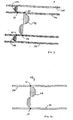
- a wellbore is shown generally at 24.
- Wellbore 24 comprises a tubing string 26 through which a fluid (not shown) flows.
- a flow profile for the fluid in tubing string 26 is shown at 28.
- Flow profile 28 may be in either direction or both directions within tubing string 26, as evidenced by opposing arrows radiating from a cross sectional slice of wellbore 24.
- Tubing string 26 is defined by a continuous wall that forms a tubular structure through which the fluid moves.
- Sensor 10 is placed in the inside diameter (ID) of tubing string 26 such that a floating head of sensor 10 is adjacently positioned to the general plane of the fluid flow and such that pressure gradients or shear gradients within tubing string 26 caused by the fluid flow can cause movement of the floating head.
- ID inside diameter
- a plurality of sensors 10 is distributed around the circumference of tubing string 26 to interpret the shear forces exerted on the surface of the tubing string 26 by the fluid at a particular cross sectional slice of wellbore 24.
- FIGURE 3 an alternate embodiment of a wellbore is shown generally at 124.
- Wellbore 124 comprises a tubing string 126 disposed substantially concentrically within a casing 125 to define an annulus therebetween. Fluids (not shown) flow within both the annulus and tubing string 126.
- a first flow profile, shown at 128, is characteristic of a first fluid flow within tubing string 126
- a second flow profile, shown at 129 is characteristic of a second fluid flow within the annulus.
- a first sensor 110 is placed within a wall of tubing string 126 such that a floating head thereof is engagable by the fluid flow within tubing string 126.
- a second sensor 111 is then placed within the wall of tubing string 126 such that a floating head thereof is engagable by the fluid flow within the annulus.
- a plurality of first sensors 110 is distributed around the inner circumference of tubing string 126 to interpret the shear forces of the fluid flow within tubing string 126 at a particular cross sectional slice of wellbore 124, while a plurality of second sensors 111 is distributed around the circumference of tubing string 126 to interpret the shear forces of the fluid flow within the annulus.
- first sensors 110 and second sensors 111 may be arranged such that sensors 110, 111 are disposed within a single cross sectional slice of the wall of tubing string 126, and may be arranged in a variety of patterns.
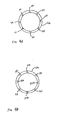
- FIGURES 4A and 4B arrangements of sensors 10 and alternating configurations of first sensors 110 and second sensors 111 are shown on cross sections of tubing strings 26, 126.
- FIGURE 4A an arrangement of sensors 10 is illustrated in which sensors 10 are each positioned to respond to a fluid flow (not shown) within tubing string 26. Although only eight sensors are depicted, any number of sensors may be incorporated into any particular cross section of tubing string 26.
- FIGURE 4B an arrangement of alternating first sensors 110 and second sensors 111 is shown in which first sensors 110 are positioned to respond to a fluid flow (not shown) within tubing string 126 and second sensors 111 are positioned to respond to a fluid flow (not shown) adjacent to the outside surface of tubing string 126.
- at least one of the sensors of the arrangement may be another type of sensor configured to measure various parameters of downhole fluids including, but not limited to, chemical species, pressure, temperature, and density.
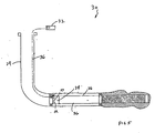
- System 30 comprises a fiber optic sensing demodulator instrument 32, flow monitoring equipment 34 disposed within wellbore 24, and a fiber optic communications cable 36 connecting fiber optic sensing demodulator instrument 32 and flow monitoring equipment 34 to provide informational communication therebetween.
- Flow monitoring equipment 34 typically includes sensing locations distributed about the circumference of tubing string 26 within wellbore 24, as described with reference to the foregoing FIGURES 4A and 4B.
- the sensing locations of flow monitoring equipment 34 preferably include fiber optic skin friction sensors 10 (sensors 10), as described above with reference to FIGURE 1 through 4.
- Fiber optic demodulator instrument 32 provides a light source to sensors 10 and converts a return signal from each sensor 10 to the required measurement data, which is typically drag force and direction of drag force. From such data, analysis software associated with fiber optic demodulator instrument 32 manipulates the measurement data to provide fluid flow characteristics data to the operator.
- Fiber optic demodulator instrument 32 is preferably located at the well head or at least at the surface of wellbore 24, but may, however, be located downhole proximate flow monitoring equipment 34 or at any point between flow monitoring equipment 34 and the surface. Alternately, fiber optic demodulator instrument 32 may be located at any point distant from wellbore 24.
- the fiber optic configurations may be substituted with electrical sensors and electrical systems.
- the movement of floating heads of electrical sensors may be converted into electrical signals, which in turn may be transmitted through conventional electrical wiring to a non-fiber optic demodulator instrument that converts the electrical signal to the required measurement data.
- the required measurement data typically includes the fluid flow rate and direction of flow at each sensing point around the circumference of the tubing string.
- This data can be determined and characterized in order to provide accurate modeling of fluid flow in the downhole environment.
- the flow rate of the fluid in the tubing string can be quantified.
- the total flow rate of the fluid is known (a value that is typically obtained from a flow metering device) or if fractional flow is derived from individual or combined sensor data, then the viscosity and density of the fluid in the tubing string can be quantified.
- multiple sensing points may be installed within the fiber optic flow characterization system for the wellbore to provide data sufficient for the calculation of the desired measurement data.
Landscapes
- Physics & Mathematics (AREA)
- Engineering & Computer Science (AREA)
- Fluid Mechanics (AREA)
- Mining & Mineral Resources (AREA)
- General Physics & Mathematics (AREA)
- Life Sciences & Earth Sciences (AREA)
- Geology (AREA)
- General Life Sciences & Earth Sciences (AREA)
- Environmental & Geological Engineering (AREA)
- Geochemistry & Mineralogy (AREA)
- Geophysics (AREA)
- Aviation & Aerospace Engineering (AREA)
- Electromagnetism (AREA)
- Health & Medical Sciences (AREA)
- Toxicology (AREA)
- Measuring Volume Flow (AREA)
- Measurement Of The Respiration, Hearing Ability, Form, And Blood Characteristics Of Living Organisms (AREA)
- Measuring And Recording Apparatus For Diagnosis (AREA)
- Indicating Or Recording The Presence, Absence, Or Direction Of Movement (AREA)
Applications Claiming Priority (3)
| Application Number | Priority Date | Filing Date | Title |
|---|---|---|---|
| US32378001P | 2001-09-20 | 2001-09-20 | |
| US323780P | 2001-09-20 | ||
| PCT/US2002/030035 WO2003025343A1 (en) | 2001-09-20 | 2002-09-20 | Fluid skin friction sensing device and method |
Publications (2)
| Publication Number | Publication Date |
|---|---|
| EP1436488A1 EP1436488A1 (en) | 2004-07-14 |
| EP1436488B1 true EP1436488B1 (en) | 2007-02-14 |
Family
ID=23260691
Family Applications (1)
| Application Number | Title | Priority Date | Filing Date |
|---|---|---|---|
| EP02761777A Expired - Lifetime EP1436488B1 (en) | 2001-09-20 | 2002-09-20 | Fluid skin friction sensing device and method |
Country Status (7)
| Country | Link |
|---|---|
| US (1) | US7168311B2 (da) |
| EP (1) | EP1436488B1 (da) |
| AU (1) | AU2002327016B2 (da) |
| CA (1) | CA2460525C (da) |
| DK (1) | DK1436488T3 (da) |
| NO (1) | NO335544B1 (da) |
| WO (1) | WO2003025343A1 (da) |
Families Citing this family (14)
| Publication number | Priority date | Publication date | Assignee | Title |
|---|---|---|---|---|
| US6997256B2 (en) * | 2002-12-17 | 2006-02-14 | Sensor Highway Limited | Use of fiber optics in deviated flows |
| US20040252748A1 (en) * | 2003-06-13 | 2004-12-16 | Gleitman Daniel D. | Fiber optic sensing systems and methods |
| GB0407982D0 (en) * | 2004-04-08 | 2004-05-12 | Wood Group Logging Services In | "Methods of monitoring downhole conditions" |
| US8770835B2 (en) * | 2006-10-06 | 2014-07-08 | Baker Hughes Incorporated | Apparatus and methods for estimating a characteristic of a fluid downhole using thermal properties of the fluid |
| US7610960B2 (en) * | 2007-04-25 | 2009-11-03 | Baker Hughes Incorporated | Depth correlation device for fiber optic line |
| US8443883B2 (en) * | 2008-07-28 | 2013-05-21 | Baker Hughes Incorporated | Apparatus and method for detecting poor hole cleaning and stuck pipe |
| US20110088462A1 (en) * | 2009-10-21 | 2011-04-21 | Halliburton Energy Services, Inc. | Downhole monitoring with distributed acoustic/vibration, strain and/or density sensing |
| DE102010012924B4 (de) | 2010-03-26 | 2013-03-28 | Karlsruher Institut für Technologie | Massenstromsensor und Verfahren zur Bestimmung des Massenstroms in einem Rohr |
| US8505625B2 (en) | 2010-06-16 | 2013-08-13 | Halliburton Energy Services, Inc. | Controlling well operations based on monitored parameters of cement health |
| US8584519B2 (en) | 2010-07-19 | 2013-11-19 | Halliburton Energy Services, Inc. | Communication through an enclosure of a line |
| US8215164B1 (en) * | 2012-01-02 | 2012-07-10 | HydroConfidence Inc. | Systems and methods for monitoring groundwater, rock, and casing for production flow and leakage of hydrocarbon fluids |
| US9823373B2 (en) | 2012-11-08 | 2017-11-21 | Halliburton Energy Services, Inc. | Acoustic telemetry with distributed acoustic sensing system |
| CA2882549C (en) * | 2013-11-08 | 2016-08-16 | Valery Sheverev | A sensor for monitoring rheologically complex flows |
| WO2016209269A1 (en) * | 2015-06-26 | 2016-12-29 | Halliburton Energy Services, Inc. | Systems and methods for characterizing materials external of a casing |
Family Cites Families (23)
| Publication number | Priority date | Publication date | Assignee | Title |
|---|---|---|---|---|
| US4274283A (en) * | 1978-10-16 | 1981-06-23 | Exxon Production Research Company | Apparatus and method for measuring fluid gel strength |
| US4496012A (en) * | 1983-05-02 | 1985-01-29 | Mobil Oil Corporation | Method for improving cuttings transport in deviated wells |
| US4821564A (en) * | 1986-02-13 | 1989-04-18 | Atlantic Richfield Company | Method and system for determining fluid pressures in wellbores and tubular conduits |
| US4794535A (en) * | 1986-08-18 | 1988-12-27 | Automated Decisions, Inc. | Method for determining economic drill bit utilization |
| US5052228A (en) * | 1986-11-19 | 1991-10-01 | Massachusetts Institute Of Technology | Shear stress measuring device |
| US4942767A (en) * | 1986-11-19 | 1990-07-24 | Massachusetts Institute Of Technology | Pressure transducer apparatus |
| US4896098A (en) * | 1987-01-08 | 1990-01-23 | Massachusetts Institute Of Technology | Turbulent shear force microsensor |
| US4879899A (en) * | 1988-04-27 | 1989-11-14 | Massachusetts Institute Of Technology | Shear stress gauge |
| US4986122A (en) * | 1989-11-08 | 1991-01-22 | Hydro Data Inc. | Fluid velocity measurement instrument |
| US5199298A (en) * | 1991-06-21 | 1993-04-06 | Massachusetts Institute Of Technology | Wall shear stress sensor |
| US5301001A (en) * | 1992-02-12 | 1994-04-05 | Center For Innovative Technology | Extrinsic fiber optic displacement sensors and displacement sensing systems |
| GB9210212D0 (en) | 1992-05-12 | 1992-06-24 | Schlumberger Ltd | Multiphase fluid flow measurement |
| US5339899A (en) * | 1992-09-02 | 1994-08-23 | Halliburton Company | Drilling fluid removal in primary well cementing |
| US5410152A (en) * | 1994-02-09 | 1995-04-25 | Halliburton Energy Services | Low-noise method for performing downhole well logging using gamma ray spectroscopy to measure radioactive tracer penetration |
| US6068394A (en) * | 1995-10-12 | 2000-05-30 | Industrial Sensors & Instrument | Method and apparatus for providing dynamic data during drilling |
| US5892860A (en) * | 1997-01-21 | 1999-04-06 | Cidra Corporation | Multi-parameter fiber optic sensor for use in harsh environments |
| US6281489B1 (en) * | 1997-05-02 | 2001-08-28 | Baker Hughes Incorporated | Monitoring of downhole parameters and tools utilizing fiber optics |
| US5872317A (en) * | 1997-11-21 | 1999-02-16 | Eastman Kodak Company | Method for measuring wall shear stress due to fluid flow in piping systems |
| US6426796B1 (en) * | 1998-09-28 | 2002-07-30 | Luna Innovations, Inc. | Fiber optic wall shear stress sensor |
| SG81333A1 (en) * | 1999-11-19 | 2001-06-19 | Inst Of High Performance Compu | Shear force microsensor |
| US6601458B1 (en) * | 2000-03-07 | 2003-08-05 | Weatherford/Lamb, Inc. | Distributed sound speed measurements for multiphase flow measurement |
| GB2383633A (en) * | 2000-06-29 | 2003-07-02 | Paulo S Tubel | Method and system for monitoring smart structures utilizing distributed optical sensors |
| US6584408B2 (en) * | 2001-06-26 | 2003-06-24 | Schlumberger Technology Corporation | Subsurface formation parameters from tri-axial measurements |
-
2002
- 2002-09-20 CA CA002460525A patent/CA2460525C/en not_active Expired - Lifetime
- 2002-09-20 DK DK02761777T patent/DK1436488T3/da active
- 2002-09-20 EP EP02761777A patent/EP1436488B1/en not_active Expired - Lifetime
- 2002-09-20 US US10/251,691 patent/US7168311B2/en not_active Expired - Lifetime
- 2002-09-20 AU AU2002327016A patent/AU2002327016B2/en not_active Ceased
- 2002-09-20 WO PCT/US2002/030035 patent/WO2003025343A1/en not_active Ceased
-
2004
- 2004-03-19 NO NO20041167A patent/NO335544B1/no not_active IP Right Cessation
Also Published As
| Publication number | Publication date |
|---|---|
| AU2002327016B2 (en) | 2008-06-05 |
| CA2460525A1 (en) | 2003-03-27 |
| US20030126921A1 (en) | 2003-07-10 |
| WO2003025343A1 (en) | 2003-03-27 |
| NO20041167L (no) | 2004-05-19 |
| NO335544B1 (no) | 2014-12-29 |
| EP1436488A1 (en) | 2004-07-14 |
| CA2460525C (en) | 2008-04-22 |
| DK1436488T3 (da) | 2007-04-02 |
| US7168311B2 (en) | 2007-01-30 |
Similar Documents
| Publication | Publication Date | Title |
|---|---|---|
| EP1436488B1 (en) | Fluid skin friction sensing device and method | |
| US6945095B2 (en) | Non-intrusive multiphase flow meter | |
| AU2002327016A1 (en) | Fluid skin friction sensing device and method | |
| RU2353766C2 (ru) | Устройство для измерения внутреннего размера ствола скважины | |
| AU779552B2 (en) | Method and apparatus for determining flow rates | |
| US6910388B2 (en) | Flow meter using an expanded tube section and sensitive differential pressure measurement | |
| US20080264182A1 (en) | Flow meter using sensitive differential pressure measurement | |
| EP2976500B1 (en) | Distributed strain and temperature sensing system | |
| GB2408328A (en) | Determining fluid hold ups using distributed fibre optic temperature sensors | |
| US20040086623A1 (en) | Storage stable pan release coating and cleaner | |
| US20160003032A1 (en) | Matrix temperature production logging tool | |
| GB2301675A (en) | Apparatus and methods for determining fluid regimes in a wellbore | |
| EP2534452A1 (en) | Polarization based fiber optic downhole flowmeter | |
| US10288463B2 (en) | Multiphase thermal flowmeter for stratified flow | |
| CN109594981A (zh) | 一种测量井下分层产量的方法 | |
| US12436009B2 (en) | Measurement of multi-phase wellbore fluid | |
| CN120740805B (zh) | 一种分布式光纤测温光缆标定装置及标定方法 | |
| AU776583B2 (en) | Multiple flow rate measurement using unsteady pressures | |
| WO2023164577A1 (en) | Measurement of multi-phase wellbore fluid | |
| CA2747368C (en) | Permanent downhole deployment of optical sensors | |
| CN120926950A (zh) | 基于fbg和管道3d轨迹的土壤沉降监测系统 | |
| GB2430269A (en) | A method and apparatus for measuring the flow rate of a fluid within tubing disposed within a downhole wellbore |
Legal Events
| Date | Code | Title | Description |
|---|---|---|---|
| PUAI | Public reference made under article 153(3) epc to a published international application that has entered the european phase |
Free format text: ORIGINAL CODE: 0009012 |
|
| 17P | Request for examination filed |
Effective date: 20040305 |
|
| AK | Designated contracting states |
Kind code of ref document: A1 Designated state(s): AT BE BG CH CY CZ DE DK EE ES FI FR GB GR IE IT LI LU MC NL PT SE SK TR |
|
| AX | Request for extension of the european patent |
Extension state: AL LT LV MK RO SI |
|
| RIN1 | Information on inventor provided before grant (corrected) |
Inventor name: BUSSEAR, TERRY, R. Inventor name: ZISK, EDWARD, J., JR. |
|
| GRAP | Despatch of communication of intention to grant a patent |
Free format text: ORIGINAL CODE: EPIDOSNIGR1 |
|
| REG | Reference to a national code |
Ref country code: DE Ref legal event code: 8566 |
|
| GRAS | Grant fee paid |
Free format text: ORIGINAL CODE: EPIDOSNIGR3 |
|
| RAP1 | Party data changed (applicant data changed or rights of an application transferred) |
Owner name: BACKER HUGUES INCORPORATED |
|
| RAP1 | Party data changed (applicant data changed or rights of an application transferred) |
Owner name: BAKER HUGHES INCORPORATED |
|
| GRAA | (expected) grant |
Free format text: ORIGINAL CODE: 0009210 |
|
| AK | Designated contracting states |
Kind code of ref document: B1 Designated state(s): DK FR GB |
|
| REG | Reference to a national code |
Ref country code: GB Ref legal event code: FG4D |
|
| REG | Reference to a national code |
Ref country code: DK Ref legal event code: T3 |
|
| ET | Fr: translation filed | ||
| PLBE | No opposition filed within time limit |
Free format text: ORIGINAL CODE: 0009261 |
|
| STAA | Information on the status of an ep patent application or granted ep patent |
Free format text: STATUS: NO OPPOSITION FILED WITHIN TIME LIMIT |
|
| 26N | No opposition filed |
Effective date: 20071115 |
|
| PGFP | Annual fee paid to national office [announced via postgrant information from national office to epo] |
Ref country code: FR Payment date: 20080917 Year of fee payment: 7 |
|
| PGFP | Annual fee paid to national office [announced via postgrant information from national office to epo] |
Ref country code: DK Payment date: 20080929 Year of fee payment: 7 |
|
| REG | Reference to a national code |
Ref country code: DK Ref legal event code: EBP |
|
| REG | Reference to a national code |
Ref country code: FR Ref legal event code: ST Effective date: 20100531 |
|
| PG25 | Lapsed in a contracting state [announced via postgrant information from national office to epo] |
Ref country code: FR Free format text: LAPSE BECAUSE OF NON-PAYMENT OF DUE FEES Effective date: 20090930 |
|
| PG25 | Lapsed in a contracting state [announced via postgrant information from national office to epo] |
Ref country code: DK Free format text: LAPSE BECAUSE OF NON-PAYMENT OF DUE FEES Effective date: 20090930 |
|
| PGFP | Annual fee paid to national office [announced via postgrant information from national office to epo] |
Ref country code: GB Payment date: 20200819 Year of fee payment: 19 |
|
| GBPC | Gb: european patent ceased through non-payment of renewal fee |
Effective date: 20210920 |
|
| PG25 | Lapsed in a contracting state [announced via postgrant information from national office to epo] |
Ref country code: GB Free format text: LAPSE BECAUSE OF NON-PAYMENT OF DUE FEES Effective date: 20210920 |