EP1436631B1 - Vorrichtung zur sicherung der verschiebung eines beweglichen organs - Google Patents
Vorrichtung zur sicherung der verschiebung eines beweglichen organs Download PDFInfo
- Publication number
- EP1436631B1 EP1436631B1 EP02783222A EP02783222A EP1436631B1 EP 1436631 B1 EP1436631 B1 EP 1436631B1 EP 02783222 A EP02783222 A EP 02783222A EP 02783222 A EP02783222 A EP 02783222A EP 1436631 B1 EP1436631 B1 EP 1436631B1
- Authority
- EP
- European Patent Office
- Prior art keywords
- value
- aeronautical
- stop
- sensor according
- axis
- Prior art date
- Legal status (The legal status is an assumption and is not a legal conclusion. Google has not performed a legal analysis and makes no representation as to the accuracy of the status listed.)
- Expired - Lifetime
Links
- 238000006073 displacement reaction Methods 0.000 title claims abstract description 10
- 238000010438 heat treatment Methods 0.000 claims description 8
- 239000000523 sample Substances 0.000 abstract description 18
- 230000035939 shock Effects 0.000 description 8
- 238000013519 translation Methods 0.000 description 6
- 238000013459 approach Methods 0.000 description 3
- 230000000694 effects Effects 0.000 description 3
- 238000000605 extraction Methods 0.000 description 3
- 238000003745 diagnosis Methods 0.000 description 2
- 238000000034 method Methods 0.000 description 2
- 238000012800 visualization Methods 0.000 description 2
- 229910001209 Low-carbon steel Inorganic materials 0.000 description 1
- 230000002159 abnormal effect Effects 0.000 description 1
- 230000007423 decrease Effects 0.000 description 1
- 238000001514 detection method Methods 0.000 description 1
- 229920001971 elastomer Polymers 0.000 description 1
- 239000000806 elastomer Substances 0.000 description 1
- 230000004907 flux Effects 0.000 description 1
- 230000002427 irreversible effect Effects 0.000 description 1
- 239000000696 magnetic material Substances 0.000 description 1
- 238000012423 maintenance Methods 0.000 description 1
- 238000004519 manufacturing process Methods 0.000 description 1
- 238000005259 measurement Methods 0.000 description 1
- 238000012544 monitoring process Methods 0.000 description 1
- 210000000056 organ Anatomy 0.000 description 1
- 238000012545 processing Methods 0.000 description 1
- 238000003303 reheating Methods 0.000 description 1
Images


Classifications
-
- G—PHYSICS
- G01—MEASURING; TESTING
- G01P—MEASURING LINEAR OR ANGULAR SPEED, ACCELERATION, DECELERATION, OR SHOCK; INDICATING PRESENCE, ABSENCE, OR DIRECTION, OF MOVEMENT
- G01P13/00—Indicating or recording presence, absence, or direction, of movement
- G01P13/02—Indicating direction only, e.g. by weather vane
- G01P13/025—Indicating direction only, e.g. by weather vane indicating air data, i.e. flight variables of an aircraft, e.g. angle of attack, side slip, shear, yaw
-
- G—PHYSICS
- G01—MEASURING; TESTING
- G01P—MEASURING LINEAR OR ANGULAR SPEED, ACCELERATION, DECELERATION, OR SHOCK; INDICATING PRESENCE, ABSENCE, OR DIRECTION, OF MOVEMENT
- G01P15/00—Measuring acceleration; Measuring deceleration; Measuring shock, i.e. sudden change of acceleration
- G01P15/02—Measuring acceleration; Measuring deceleration; Measuring shock, i.e. sudden change of acceleration by making use of inertia forces using solid seismic masses
- G01P15/03—Measuring acceleration; Measuring deceleration; Measuring shock, i.e. sudden change of acceleration by making use of inertia forces using solid seismic masses by using non-electrical means
- G01P15/032—Measuring acceleration; Measuring deceleration; Measuring shock, i.e. sudden change of acceleration by making use of inertia forces using solid seismic masses by using non-electrical means by measuring the displacement of a movable inertial mass
- G01P15/036—Measuring acceleration; Measuring deceleration; Measuring shock, i.e. sudden change of acceleration by making use of inertia forces using solid seismic masses by using non-electrical means by measuring the displacement of a movable inertial mass for indicating predetermined acceleration values
Definitions
- the invention relates to a device for securing the displacement of a movable member.
- the invention finds particular utility in incidence probes used in aeronautics.
- Such probes mounted on the skin of an aircraft, measure the incidence of a flow of air relative to the aircraft.
- These probes contribute to the safety of the flight of the aircraft. In particular, they make it possible to prevent dropping out. They are located generally at the front of the aircraft, often in a horizontal position (so-called 3 o'clock or 9 o'clock position).
- These probes may comprise a pallet movable in rotation about an axis perpendicular to the skin of the aircraft.
- the movable pallet is oriented in the axis of the flow surrounding it.
- the orientation of the mobile pallet makes it possible to determine the incidence of the aircraft.
- the pallet is an appendage located outside the skin of the aircraft. Like all appendages, the risk is great to damage them during ground maintenance operations of the aircraft.
- a shock on the movable pallet can have any direction and it would have that this direction is exactly that of the plane of symmetry of the pallet so that it does not involve rotation of the pallet.
- a shock tends to deform the pallet in a direction where its inertia is greatest.
- This shock is therefore unlikely to damage the general shape of the pallet and will deform only the leading edge thereof.
- Such a deformation is always visible.
- These shocks constitute the bulk of the damage that the pallet can undergo.
- these shocks are likely to veil the pallet, resulting in poor impact measurements. This type of deformation is, moreover, not very visible.
- the moving pallets can not perform a full rotation of 360 ° around their axis of rotation.
- the rotation is limited by stops leaving for example an amplitude of the order of 90 ° as for example described in the documents US 5,438,865 A and US 3,882,721 A .
- the object of the invention is to detect shocks liable to deform the pallet. This type of shock causes an abnormal effort of the pallet on one of its stops. When the detection is effective, it is necessary to recalibrate the pallet, for example in the wind tunnel.
- the subject of the invention is an aeronautical probe as claimed.
- the nominal force is defined as a limit force exerted on the movable member. If the value of the force exerted on the stopper exceeds the value of the nominal or limit force, the movable member may suffer irreversible damage such as permanent deformation. Exceeding the value of the nominal force indicates the existence of damage to the moving part. The nominal effort is therefore not zero.
- the energy used by the storage means for their operation comes only from the energy provided by the force exerted on the stop by the movable member.
- the storage means comprise means for modifying the position of the stop.
- the stop retracts when the force exerted on the stop by the movable member exceeds the value of a nominal force. More precisely, the stop is in a first position as long as the value of the nominal force is not reached and the stop reaches a second position when the value of the nominal force is exceeded. The stop retains the second position even when the value of the force exerted on the stop by the movable member becomes less than the value of the nominal force after having exceeded it.
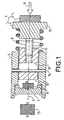
- the device represented on the figure 1 comprises a stop 1 on which a movable member, not shown, is intended to rest.
- the abutment 1 comprises a rigid portion 2 and an elastic portion 3, integral with the rigid portion 2, for example elastomer, on which is established the contact with the movable member.
- the abutment 1 is capable of moving in translation along an axis 4.
- the movement of the movable member can also be in translation along the axis 4. This movement can just as well be done along an axis of rotation perpendicular to the plane of the figure 1 .
- the movable member then comprises an element whose movement substantially tangents the axis 4 at the contact of this element with the abutment 1 on the elastic portion 3.
- the translational movement of the abutment along the axis 4 is effected by relative to a stop body 5 in the form of a hollow tube 4, for example cylindrical axis, inside which the stop 1 is likely to move.
- a permanent magnet 6 is integral with the abutment body 5.
- the permanent magnet 6 is for example connected to the abutment body 5 by means of a magnet support 7.
- the rigid part 2 is made of a magnetic material such as it can be attracted by the permanent magnet 6 when the rigid part 2 is situated in the vicinity of the permanent magnet 6.
- the magnetic flux can pass through the magnet support 7, and the abutment body 5.
- the rigid part 2, the magnet support 7, and the abutment body 5 can be made of mild steel.
- An elastic element 8 such as for example a helical spring, holds the rigid part 2 at a given distance from the permanent magnet 6.
- the elastic element 8 bears between the rigid part 2 and the abutment body 5.
- the value of the force exerted on the abutment 1 by the movable member is sufficient, in other words, if the value of the force exerted exceeds the value of a nominal force, the rigid part 2 comes into contact with the permanent magnet 6, and the magnetic force exerted by it, is such that the rigid portion 2 is maintained in contact with the permanent magnet 6, even when the force exerted on the stop 1 by the movable member has disappeared.
- the device comprises means for adjusting the value of the nominal force.
- the adjustment of the value of the nominal force can be done by choosing the dimensions and the stiffness of the elastic element 8.
- the rigid part 2 can comprise means for adjusting its length along the axis 4 in order to allow the adjustment of the nominal force, even after the choice of a resilient element 8 determined.
- These adjustment means advantageously comprise a piston 10 slidable inside the abutment body 5, a screw-nut system 11 and a shouldered shaft 12.
- the elastic portion 3 is integral with the shouldered shaft 12.
- the elastic element 8 is supported between the shouldered shaft 12 and the abutment body 5.
- the screw-nut system 11 moves the piston 10 relative to the shouldered shaft 12. By operating the screw-nut system 11, the distance between the piston 10 and the permanent magnet 6, which allows, therefore, to adjust the value of the nominal force.
- the abutment 1 comprises means for limiting its displacement in translation along the axis 4, relative to the abutment body 5.
- These means comprise for example an oblong hole 13 made in the rigid part 2 or, more precisely in the piston 10, as well as a pin 14.
- the oblong hole 13 is radial with respect to the axis 4.
- the pin 14 is fixed in the abutment body 5 and passes through the oblong hole 13.
- the displacement of the abutment 1 is limited by the dimensions of the oblong hole 13 to inside which the pin 14 moves relative to the piston 10.
- the means for limiting the translational movement along the axis 4 of the abutment to maintain the elastic element 8 slightly compressed, even in the absence of force exerted by the movable member on the abutment 5.
- the resetting means may comprise a second permanent magnet 15 whose power is substantially greater than that of the permanent magnet 6.
- the second permanent magnet 15 is oriented such that its pole, the closest to the magnet support 7, is of the same polarity as the pole in contact with ec the magnet support 7 of the first magnet 6.
- the figure 2 represents a second embodiment of a retractable abutment 20.
- the abutment 20 comprises a piston 21, integral with the elastic portion 3, capable of translational movement along the axis 4 under the effect of a force exerted in the direction of the arrow 9 by the movable member.
- the piston 21 moves in translation inside an abutment body 22.
- the piston 21 comprises a radial cylindrical hole 23 passing through it from one side to the other. Inside the hole 23, there is an elastic element 24, such as for example, a helical spring.
- Two balls 25 and 26 rest on each of the ends of the elastic element 24. The two balls 25 and 26 can slide inside the hole 23 when a radial force is exerted relative to the axis 4, on each of them.
- the piston 21 is in a first position with respect to the abutment body 22. This position which is represented on the figure 2 .
- the balls 25 and 26 are partly housed in a groove 27 formed in the abutment body 22.
- the groove 27 is, for example, toric around the axis 4.
- the small diameter of the torus is substantially that of balls 25 and 26.
- the elastic element 24 retracts under a centripetal thrust of the balls 25 and 26. This centripetal thrust is due to the fact that the balls 25 and 26 leave the groove 27.
- the piston 21 then moves inside the stop body 22 until the balls 25 and 26 reach a second position in which they are housed in a second groove 28 formed in the stop body 22.
- the groove 28 is for example toric about the axis 4.
- the device comprises means for adjusting the value of the nominal force. This adjustment can be made during the production of the component parts of the device.
- the depth of the groove 27 makes it possible to adjust the value of the nominal force. More precisely, we define an angle ⁇ between the axis 4 and a tangent to the groove 27 at the point where one of the balls 25 or 26 can escape the groove 27 when a force is exerted by the movable member on the stop 20 in the direction of the arrow 9.
- the value of the angle ⁇ determines the value of the nominal force for a given elastic element 24. The higher the angle ⁇ , the higher the value of the nominal force increases.
- the depth of the groove 28 it is possible to adjust the force required to reset the stop 20. More specifically, the value of the angle ⁇ that the axis 4 with the tangent to the groove 28 at the point where one of the balls 25 or 26 can escape the groove 28 to reset the stop 20, determines the effort required to reset the stop.
- the adjustment of the value of the angles ⁇ and ⁇ can be done by increasing the inside diameter 32 of the abutment body 22 between the grooves 27 and 28.
- the device comprises means for preventing the stop 20 from exceeding the second position.
- the angle made by the axis 4, with the tangent to the groove 28, at the point farthest from the elastic portion 3, is a right angle.
- the elastic element 33 is, for example, a helical spring that compresses in the direction of the axis 4 when the movable member presses against the stop 20.
- the device described using the figure 2 comprises two balls 25 and 26. It is also conceivable to define a device having only one ball.
- the hole 23, inside which the ball can slide, is then a blind hole.
- the function performed by the grooves 27 and 28, ie materializing the positions of the balls 25 and 26 in the abutment body 22, can be filled by radial cylindrical holes relative to the axis 4 and arranged in the body The diameter of these holes makes it possible to adjust the value of the nominal and resetting forces of the abutment 20.
- These holes can be tapped and a screw mounted in each hole by the outside of the abutment body 22 makes it possible to adjust the value of effort
- the screw, mounted in a hole replacing the groove 27 also facilitates the extraction of the abutment 20 of the abutment body 22 by reducing the value of the effort required for this extraction. The extraction is done by pushing the stop 20 in the opposite direction to the arrow 9 beyond the first position.
- the figure 3 represents an incidence probe 40 in top view.
- the incidence probe 40 comprises a movable pallet 41 rotated about an axis 42 perpendicular to the plane of the figure 3 .
- the movable pallet 41 is intended to orient itself in the axis of an air flow surrounding it and whose usual orientation is represented by the arrow 43.
- the movement of the movable pallet 41 is limited angularly, for example at + or - 45 ° around the position of the pallet in its usual orientation shown on the figure 3 . Stops, such as those described with the help of figures 1 and 2 prevent the movable pallet 41 from exceeding the angular limitation.
- the movable member is then secured to the movable pallet and the abutment body 5 or 22 is secured to a fixed portion 46 of the incidence probe 40.
- Markings 44 and 45 carried on the fixed part 46 of the bearing probe 40, make it possible to visualize the maximum displacement of the mobile pallet 41. More specifically, when the movable member presses, without exceeding the value of the effort nominal, on one of the abutments 1 or 20, the plane of symmetry 47 of the movable pallet 41 is aligned with one of the marks 44 or 45.
- a mark 48 carried by the movable pallet 41 and aligned with the plane of symmetry 47, is located in the vicinity of the markers 44 and 45. The mark 48 facilitates the visualization of the position of the movable pallet 41 relative to the fixed part 46.
- the embodiments presented with the help of figures 1 and 2 do not make it possible to carry out the diagnosis of exceeding the value of the nominal force during the flight of an aircraft bearing the incidence probe 40. Indeed, in flight, it is very unlikely that the mobile pallet 41 will reach one of its abutments 1 or 20. It is possible to overcome this problem by proposing a device whose realization is described using the figure 4 .
- the storage means comprise a switch 50 with two stable positions. The switch 50 is in a first position, that represented on the figure 4 , as long as the value of a force exerted on an abutment 51 does not exceed the value of the nominal force. On the other hand, the switch 50 is in a second position as soon as the value of the force exerted on the stop 51 has exceeded the value of the nominal force.
- the stop 51 comprises a piston 52, integral with the elastic portion 3, capable of translational movement along the axis 4, under the effect of a force exerted in the direction of the arrow 9 by the movable member.
- the piston 52 moves in translation inside a stop body 53.
- a first end 54 of a rod 55 is integral with the piston 52.
- the rod 55 extends along the axis 4.
- a second end 56 of the rod 55 is able to maneuver a lever 57 of the switch 50.
- the lever 57 allows to change the state (open or closed) of electrical contacts belonging to the switch 50.
- the switch 50 is secured to the stop member 53.
- An elastic member 58 opposes the force exerted by the movable member on the stop 51.
- the elastic element 58 for example a helical spring, is supported, on the one hand, on the piston 52 in the vicinity of the first end 54 of the rod 55 and, secondly, on a cylinder head 59 integral with the stop body 53.
- the rod 55 passes through the cylinder head 59 and its translational movement in the direction opposite to the arrow 9 can be prevented for example by means of a split ring 60 secured to the rod 55 and bearing against the cylinder head 59 in the absence of force on the stop 51.
- the lever 57 does not modify the state of the contacts of the switch 50 and returns to the position shown in solid lines on the figure 4 when the force exerted by the mobile organ has disappeared.
- the lever 57 modifies the state of the contacts of the switch 50 and passes into the position 57a of the lever 57, position represented in dotted lines on the figure 4 .
- Changing the state of the contacts of the switch 50 may inform a processing unit outside the device and not shown, on exceeding the value of the nominal force.
- the switch 50 can interrupt a heating circuit belonging to the incidence probe 40.
- the switch 50 is located in series in the heating circuit and opens the circuit reheating when in its second position 57a.
- the switch 50 then makes it possible not to increase the number of electrical paths leaving the bearing probe 40.
- the heating circuit is generally monitored by a control unit of the aircraft. When the heating circuit is interrupted, the incidence probe 40 is declared out of service by the control unit. No additional element is added to the monitoring means already present in the aircraft. In contrast, the switch 50 located in series in the heating circuit degrades the reliability of this circuit.
- the device represented on the figure 4 also comprises means for adjusting the value of the nominal force. To carry out this adjustment, it is possible, for example, to move the yoke 59 along the axis 4 with respect to the abutment body 53. This displacement can be implemented by means of a threading 61 between the yoke 59 and the body of stop 53.
Landscapes
- Physics & Mathematics (AREA)
- General Physics & Mathematics (AREA)
- Engineering & Computer Science (AREA)
- Aviation & Aerospace Engineering (AREA)
- A Measuring Device Byusing Mechanical Method (AREA)
- Injection Moulding Of Plastics Or The Like (AREA)
Claims (11)
- Aeronautischer Sensor, der Folgendes umfasst:• einen Flügel, der einen Ansatz bildet, der auf der Außenseite der Haut eines Flugfahrzeugs angeordnet werden kann, wobei der Ansatz ein bewegliches Teil bildet,• und eine Vorrichtung zum Sichern der Bewegung des beweglichen Teils, wobei die Bewegung entlang einer Achse (4; 42) geführt und durch wenigstens einen Anschlag (1; 20; 51) begrenzt wird,dadurch gekennzeichnet, dass die Sicherungsvorrichtung Mittel zum Speichern der Überschreitung eines Kraftnennwertes durch eine Kraft umfasst, die von dem beweglichen Teil entlang der Achse (4; 42) auf den Anschlag (1; 20; 51) ausgeübt wird.
- Aeronautischer Sensor nach Anspruch 1, dadurch gekennzeichnet, dass die Achse eine Rotationsachse (42) ist.
- Aeronautischer Sensor nach einem der vorherigen Ansprüche, dadurch gekennzeichnet, dass die Energie, die von den Speichermitteln für deren Betrieb verbraucht wird, nur von der Energie kommt, die von der Kraft erzeugt wird, die vom beweglichen Teil auf den Anschlag (1; 20; 51) ausgeübt wird.
- Aeronautischer Sensor nach einem der vorherigen Ansprüche, dadurch gekennzeichnet, dass die Speichermittel Mittel zum Modifizieren der Position des Anschlags (1; 20; 51) aufweisen.
- Aeronautischer Sensor nach Anspruch 4, dadurch gekennzeichnet, dass der Anschlag (1; 20) in einer ersten Position ist, solange der Kraftnennwert nicht erreicht ist, und dadurch, dass der Anschlag (1; 20) eine zweite Position erreicht, wenn der Kraftnennwert überschritten wird.
- Aeronautischer Sensor nach Anspruch 5, dadurch gekennzeichnet, dass der Anschlag (1; 20) die zweite Position beibehält.
- Aeronautischer Sensor nach Anspruch 6, dadurch gekennzeichnet, dass die Vorrichtung Mittel (15; 29) umfasst, um den Anschlag (1; 20) in die erste Position zurückzubringen.
- Aeronautischer Sensor nach einem der Ansprüche 5 bis 7, dadurch gekennzeichnet, dass die Vorrichtung Mittel (28) aufweist, um zu verhindern, dass der Anschlag (1; 20) über die zweite Position hinaus geht.
- Aeronautischer Sensor nach einem der vorherigen Ansprüche, dadurch gekennzeichnet, dass die Vorrichtung Mittel (8; 11; 27) zum Regeln des Kraftnennwertes umfasst.
- Aeronautischer Sensor nach einem der vorherigen Ansprüche, dadurch gekennzeichnet, dass die Speichermittel einen Schalter (50) mit zwei stabilen Positionen beinhaltet, dadurch, dass der Schalter (50) in einer ersten Position ist, solange der Kraftnennwert nicht erreicht ist, und dadurch, dass der Schalter (50) in einer zweiten Position ist, sobald der Kraftnennwert überschritten wird.
- Aeronautischer Sensor nach Anspruch 10, dadurch gekennzeichnet, dass der bewegliche Teil ein beweglicher Flügel (41) ist, der so ausgelegt ist, dass er sich entlang der Achse eines den beweglichen Teil umgebenden Luftstroms ausrichtet, dadurch, dass der bewegliche Flügel (41) eine Heizschaltung beinhaltet, dadurch, dass der Schalter (50) in Serie mit der Heizschaltung geschaltet ist, und dadurch, dass der Schalter (50) die Heizschaltung öffnet, wenn er in seiner zweiten Position (57a) ist.
Applications Claiming Priority (3)
| Application Number | Priority Date | Filing Date | Title |
|---|---|---|---|
| FR0112868 | 2001-10-05 | ||
| FR0112868A FR2830620B1 (fr) | 2001-10-05 | 2001-10-05 | Dispositif de securisation du deplacement d'un organe mobile |
| PCT/FR2002/003312 WO2003042706A1 (fr) | 2001-10-05 | 2002-09-27 | Dispositif de securisation du deplacement d'un organe mobile |
Publications (2)
| Publication Number | Publication Date |
|---|---|
| EP1436631A1 EP1436631A1 (de) | 2004-07-14 |
| EP1436631B1 true EP1436631B1 (de) | 2011-01-05 |
Family
ID=8867986
Family Applications (1)
| Application Number | Title | Priority Date | Filing Date |
|---|---|---|---|
| EP02783222A Expired - Lifetime EP1436631B1 (de) | 2001-10-05 | 2002-09-27 | Vorrichtung zur sicherung der verschiebung eines beweglichen organs |
Country Status (5)
| Country | Link |
|---|---|
| US (1) | US7275428B2 (de) |
| EP (1) | EP1436631B1 (de) |
| DE (1) | DE60238848D1 (de) |
| FR (1) | FR2830620B1 (de) |
| WO (1) | WO2003042706A1 (de) |
Families Citing this family (9)
| Publication number | Priority date | Publication date | Assignee | Title |
|---|---|---|---|---|
| GB2465397C (en) * | 2008-11-17 | 2013-04-10 | Messier Dowty Ltd | Load indicator |
| WO2012122449A2 (en) | 2011-03-10 | 2012-09-13 | Shockwatch, Inc. | Impact indicator |
| US9884685B2 (en) * | 2014-05-28 | 2018-02-06 | The Boeing Company | External case heater for an angle of attack sensor |
| EP4339984A3 (de) | 2017-06-23 | 2024-05-22 | Shockwatch, Inc. | Aufprallindikator |
| US11046454B2 (en) | 2017-08-01 | 2021-06-29 | Shockwatch, Inc. | Unmanned aerial vehicle impact monitoring system |
| US11041770B2 (en) | 2017-10-26 | 2021-06-22 | Shockwatch, Inc. | Impact indicator |
| US11112425B2 (en) | 2019-09-30 | 2021-09-07 | Shockwatch, Inc. | Impact indicator |
| CN115702330A (zh) | 2020-05-21 | 2023-02-14 | 肖克沃奇股份有限公司 | 撞击指示器 |
| US11802888B2 (en) | 2020-09-21 | 2023-10-31 | Rosemount Aerospace Inc. | Damage detection for rotary angle measurement sensors |
Citations (5)
| Publication number | Priority date | Publication date | Assignee | Title |
|---|---|---|---|---|
| DE2856424A1 (de) * | 1977-12-30 | 1979-07-05 | Uitgeverij Meander Bv | Vorrichtung zum zaehlen von kraftimpulsen |
| GB2270200A (en) * | 1992-08-25 | 1994-03-02 | Takata Corp | Acceleration sensor |
| US5334963A (en) * | 1992-10-22 | 1994-08-02 | The University Of Alabama In Huntsville | Inertia and inductance switches |
| DE19509931A1 (de) * | 1994-03-25 | 1995-10-19 | Smc Kk | Stoßbelastungssensor |
| US5966066A (en) * | 1994-06-10 | 1999-10-12 | Case Western Reserve University | Micromechanical memory sensor |
Family Cites Families (7)
| Publication number | Priority date | Publication date | Assignee | Title |
|---|---|---|---|---|
| US3882721A (en) * | 1973-11-16 | 1975-05-13 | Rosemount Inc | Vane type airflow sensor |
| FR2417433A1 (fr) * | 1978-02-20 | 1979-09-14 | France Etat | Dispositif mecanique de detection des atterrissages durs |
| US5438865A (en) * | 1993-12-16 | 1995-08-08 | Safe Flight Instrument Corporation | Angle of attack sensor |
| US5485758A (en) * | 1993-12-27 | 1996-01-23 | Trw Vehicle Safety Systems Inc. | Method and apparatus for simulating vehicle side impacts |
| US6023984A (en) * | 1998-01-28 | 2000-02-15 | Breed Automotive Technology, Inc. | Dynamic proximity test apparatus |
| DE10052372A1 (de) * | 2000-10-20 | 2002-05-02 | Bhs Corr Masch & Anlagenbau | Verfahren zur Regelung der Höhe eines Walzenspaltes einer Beleimungs-Vorrichtung für eine Wellpappe-Bahn und Vorrichtung zur Durchführung des Verfahrens |
| JP2004130979A (ja) * | 2002-10-11 | 2004-04-30 | Alps Electric Co Ltd | 力覚付与型入力装置 |
-
2001
- 2001-10-05 FR FR0112868A patent/FR2830620B1/fr not_active Expired - Fee Related
-
2002
- 2002-09-27 US US10/489,429 patent/US7275428B2/en not_active Expired - Fee Related
- 2002-09-27 EP EP02783222A patent/EP1436631B1/de not_active Expired - Lifetime
- 2002-09-27 WO PCT/FR2002/003312 patent/WO2003042706A1/fr not_active Ceased
- 2002-09-27 DE DE60238848T patent/DE60238848D1/de not_active Expired - Lifetime
Patent Citations (5)
| Publication number | Priority date | Publication date | Assignee | Title |
|---|---|---|---|---|
| DE2856424A1 (de) * | 1977-12-30 | 1979-07-05 | Uitgeverij Meander Bv | Vorrichtung zum zaehlen von kraftimpulsen |
| GB2270200A (en) * | 1992-08-25 | 1994-03-02 | Takata Corp | Acceleration sensor |
| US5334963A (en) * | 1992-10-22 | 1994-08-02 | The University Of Alabama In Huntsville | Inertia and inductance switches |
| DE19509931A1 (de) * | 1994-03-25 | 1995-10-19 | Smc Kk | Stoßbelastungssensor |
| US5966066A (en) * | 1994-06-10 | 1999-10-12 | Case Western Reserve University | Micromechanical memory sensor |
Also Published As
| Publication number | Publication date |
|---|---|
| EP1436631A1 (de) | 2004-07-14 |
| US20040231428A1 (en) | 2004-11-25 |
| WO2003042706A1 (fr) | 2003-05-22 |
| DE60238848D1 (de) | 2011-02-17 |
| FR2830620B1 (fr) | 2004-01-16 |
| FR2830620A1 (fr) | 2003-04-11 |
| US7275428B2 (en) | 2007-10-02 |
Similar Documents
| Publication | Publication Date | Title |
|---|---|---|
| EP2082957B1 (de) | Verfahren und Vorrichtung zum dynamischen Ausgleich eines Schaufelblatts | |
| EP1436631B1 (de) | Vorrichtung zur sicherung der verschiebung eines beweglichen organs | |
| CA2621842C (fr) | Soufflante de turbomachine | |
| EP2612044B1 (de) | Koppelstange für eine Luftfahrtvorrichtung und Luftfahrtvorrichtung mit einer solchen Koppelstange | |
| EP3333646A1 (de) | Tragbarer gegenstand, der einen drehbaren steuerstab umfasst, dessen betätigung durch zwei induktionssensoren erkannt wird | |
| FR3081836A1 (fr) | Ensemble propulsif d'aeronef et procede de verification de l'integrite d'une attache moteur de l'ensemble propulsif | |
| EP3333647B1 (de) | Tragbarer gegenstand, der einen drehbaren steuerstab umfasst, dessen betätigung durch die messung einer magnetischen induktion erfasst wird | |
| EP0194179A1 (de) | Selbsteinstellbarer Bowdenzug mit elektrischem Taster zur Funktionsanzeige | |
| FR3051908B1 (fr) | Dispositif anti-flexion pour sonde de turbomachine | |
| FR2476407A1 (fr) | Dispositif de centrage d'un rotor | |
| EP3080475B1 (de) | Trommelbremse mit bremsbackenhalter | |
| EP3418814A1 (de) | Bedienungsvorrichtung mit drücker-krone für ein kleines tragbares objekt | |
| EP0432557A1 (de) | Gerät zur Messung einer Abmessung eines Objekts | |
| EP1952413A1 (de) | Steuereinrichtung mit mitteln zum indizieren der position von steuermitteln | |
| EP3333648B1 (de) | Vorrichtung zur steuerung von mindestens zwei elektronischen und/oder mechanischen funktionen eines tragbaren gegenstands | |
| EP2386831B1 (de) | Kreuzhebelartige Steuervorrichtung | |
| FR3011304A1 (fr) | Dispositif de transmission de mouvement sans jeu a un capteur de position et dispositif de detection de position correspondant | |
| EP3488964A1 (de) | Vorrichtung zur handhabung einer hohlachse zum erzeugen einer schwenkbaren verbindung zwischen einem ersten und einem zweiten element | |
| EP1158275A1 (de) | Axialpositionsgeber | |
| FR2954826A1 (fr) | Table d'essai destinee au controle de tarage d'une soupape | |
| EP0569288B1 (de) | Hubschrauberheckrotor mit einem Detektor der Überschreitung einer Verschiebungschwellenspannung in der Steigungsregelung | |
| FR3025903A1 (fr) | Dispositif d'entrée de données et ses moyens de freinage | |
| EP3094981B1 (de) | Mechanische vorrichtung zur detektion von winkelbeschleunigung | |
| EP0006051A1 (de) | Elektrodynamometrischer Detektor mit Überlastungsanzeiger | |
| EP3662567B1 (de) | Rotierende elektrische maschine mit einem verkeilungselement |
Legal Events
| Date | Code | Title | Description |
|---|---|---|---|
| PUAI | Public reference made under article 153(3) epc to a published international application that has entered the european phase |
Free format text: ORIGINAL CODE: 0009012 |
|
| 17P | Request for examination filed |
Effective date: 20040506 |
|
| AK | Designated contracting states |
Kind code of ref document: A1 Designated state(s): AT BE BG CH CY CZ DE DK EE ES FI FR GB GR IE IT LI LU MC NL PT SE SK TR |
|
| 17Q | First examination report despatched |
Effective date: 20090818 |
|
| GRAP | Despatch of communication of intention to grant a patent |
Free format text: ORIGINAL CODE: EPIDOSNIGR1 |
|
| GRAS | Grant fee paid |
Free format text: ORIGINAL CODE: EPIDOSNIGR3 |
|
| GRAA | (expected) grant |
Free format text: ORIGINAL CODE: 0009210 |
|
| AK | Designated contracting states |
Kind code of ref document: B1 Designated state(s): DE FR GB |
|
| REG | Reference to a national code |
Ref country code: GB Ref legal event code: FG4D Free format text: NOT ENGLISH |
|
| REF | Corresponds to: |
Ref document number: 60238848 Country of ref document: DE Date of ref document: 20110217 Kind code of ref document: P |
|
| REG | Reference to a national code |
Ref country code: DE Ref legal event code: R096 Ref document number: 60238848 Country of ref document: DE Effective date: 20110217 |
|
| PLBE | No opposition filed within time limit |
Free format text: ORIGINAL CODE: 0009261 |
|
| STAA | Information on the status of an ep patent application or granted ep patent |
Free format text: STATUS: NO OPPOSITION FILED WITHIN TIME LIMIT |
|
| 26N | No opposition filed |
Effective date: 20111006 |
|
| REG | Reference to a national code |
Ref country code: DE Ref legal event code: R097 Ref document number: 60238848 Country of ref document: DE Effective date: 20111006 |
|
| REG | Reference to a national code |
Ref country code: DE Ref legal event code: R119 Ref document number: 60238848 Country of ref document: DE Effective date: 20120403 |
|
| PG25 | Lapsed in a contracting state [announced via postgrant information from national office to epo] |
Ref country code: DE Free format text: LAPSE BECAUSE OF NON-PAYMENT OF DUE FEES Effective date: 20120403 |
|
| PGFP | Annual fee paid to national office [announced via postgrant information from national office to epo] |
Ref country code: GB Payment date: 20120926 Year of fee payment: 11 |
|
| GBPC | Gb: european patent ceased through non-payment of renewal fee |
Effective date: 20130927 |
|
| PG25 | Lapsed in a contracting state [announced via postgrant information from national office to epo] |
Ref country code: GB Free format text: LAPSE BECAUSE OF NON-PAYMENT OF DUE FEES Effective date: 20130927 |
|
| REG | Reference to a national code |
Ref country code: FR Ref legal event code: PLFP Year of fee payment: 14 |
|
| PGFP | Annual fee paid to national office [announced via postgrant information from national office to epo] |
Ref country code: FR Payment date: 20150825 Year of fee payment: 14 |
|
| REG | Reference to a national code |
Ref country code: FR Ref legal event code: ST Effective date: 20170531 |
|
| PG25 | Lapsed in a contracting state [announced via postgrant information from national office to epo] |
Ref country code: FR Free format text: LAPSE BECAUSE OF NON-PAYMENT OF DUE FEES Effective date: 20160930 |