EP1437206A2 - Dispositif de perçage de verres de lunettes - Google Patents
Dispositif de perçage de verres de lunettes Download PDFInfo
- Publication number
- EP1437206A2 EP1437206A2 EP04000185A EP04000185A EP1437206A2 EP 1437206 A2 EP1437206 A2 EP 1437206A2 EP 04000185 A EP04000185 A EP 04000185A EP 04000185 A EP04000185 A EP 04000185A EP 1437206 A2 EP1437206 A2 EP 1437206A2
- Authority
- EP
- European Patent Office
- Prior art keywords
- drilling
- spectacle lens
- glass
- video camera
- lens
- Prior art date
- Legal status (The legal status is an assumption and is not a legal conclusion. Google has not performed a legal analysis and makes no representation as to the accuracy of the status listed.)
- Granted
Links
Images
Classifications
-
- B—PERFORMING OPERATIONS; TRANSPORTING
- B23—MACHINE TOOLS; METAL-WORKING NOT OTHERWISE PROVIDED FOR
- B23Q—DETAILS, COMPONENTS, OR ACCESSORIES FOR MACHINE TOOLS, e.g. ARRANGEMENTS FOR COPYING OR CONTROLLING; MACHINE TOOLS IN GENERAL CHARACTERISED BY THE CONSTRUCTION OF PARTICULAR DETAILS OR COMPONENTS; COMBINATIONS OR ASSOCIATIONS OF METAL-WORKING MACHINES, NOT DIRECTED TO A PARTICULAR RESULT
- B23Q17/00—Arrangements for observing, indicating or measuring on machine tools
- B23Q17/24—Arrangements for observing, indicating or measuring on machine tools using optics or electromagnetic waves
-
- B—PERFORMING OPERATIONS; TRANSPORTING
- B23—MACHINE TOOLS; METAL-WORKING NOT OTHERWISE PROVIDED FOR
- B23Q—DETAILS, COMPONENTS, OR ACCESSORIES FOR MACHINE TOOLS, e.g. ARRANGEMENTS FOR COPYING OR CONTROLLING; MACHINE TOOLS IN GENERAL CHARACTERISED BY THE CONSTRUCTION OF PARTICULAR DETAILS OR COMPONENTS; COMBINATIONS OR ASSOCIATIONS OF METAL-WORKING MACHINES, NOT DIRECTED TO A PARTICULAR RESULT
- B23Q17/00—Arrangements for observing, indicating or measuring on machine tools
- B23Q17/22—Arrangements for observing, indicating or measuring on machine tools for indicating or measuring existing or desired position of tool or work
-
- B—PERFORMING OPERATIONS; TRANSPORTING
- B28—WORKING CEMENT, CLAY, OR STONE
- B28D—WORKING STONE OR STONE-LIKE MATERIALS
- B28D1/00—Working stone or stone-like materials, e.g. brick, concrete or glass, not provided for elsewhere; Machines, devices, tools therefor
- B28D1/14—Working stone or stone-like materials, e.g. brick, concrete or glass, not provided for elsewhere; Machines, devices, tools therefor by boring or drilling
- B28D1/143—Working stone or stone-like materials, e.g. brick, concrete or glass, not provided for elsewhere; Machines, devices, tools therefor by boring or drilling lens-drilling machines
Definitions
- the invention relates to a device for drilling glasses, in particular for rimless glasses.
- the temples and nose bridge of rimless glasses are usually attached to the screwed on pre-ground lenses so that it becomes necessary in the shape-cut lenses to drill the appropriate holes. It is the location, the position of these holes in the respective lenses of the shape of the Spectacle glasses as well as the nose bridge and the temple depend. To simplify the Drilling of the holes in the respective lenses are currently carried out by one A large number of manufacturers of spectacle lenses offer so-called prescription glasses, which meet the Opticians are an aid to the appropriate in the glasses to be used To be able to drill holes at the desired locations.
- Such glasses or templates for spectacle lenses serve among other things to determine the locations at which the spectacle lens is to be drilled or the To determine the position at which a fitting or frame part on the lens to Example to be attached by gluing.
- a template you can too Markings are made on an eyeglass lens, and stencils are in particular also necessary when glasses or nose bridges / nose bridges to be attached to the lenses for rimless glasses.
- Such stencils are known in a variety of designs, describes the DE 44 38 634 A1 a template through which the place where a hole in an eyeglass should be introduced, can be determined.
- This template can be used be transparent film that is placed on the lens over an adhesive surface can.
- the adhesive effect is designed so that the film slips on the one hand compared to the glass during processing operations, on the other hand but the film can be easily removed from the glass even after processing.
- This type of stencil is difficult to use in that it involves placing one flat adhesive film on a curved lens surface usually not straight away succeed. Since the film adheres, it cannot be moved or rotated in relation to the glass rather, it has to be completely detached from the glass, and finally it is suitable such a film only a little as a drilling template.
- WO 94/04957 A1 teaches how to mark spectacle lenses known, which also serves as a template for the edge processing of a lens.
- the gauge is disc-shaped with two mirror-symmetrical depressions and an edge constant thickness.
- a template for an eyeglass lens with at least one hole or a marking is described in DE 197 49 631 C2, in which the template with a blocker placed on the eyeglass lens is non-displaceably and non-rotatably connectable to one another, and thus the position of the hole or the marking should be relative to be fixed to the lens.
- This solution also suffers from the disadvantage that a template / drilling aid is placed on the spectacle lens to be machined, which serves to guide drilling tools or to guide and accommodate marking elements. This does not rule out that the surfaces of the lenses are damaged by the templates / drilling aids to be attached.
- a method of marking or drilling holes in glasses and one Device for carrying out the method is known from DE 198 04 428 A1 become, in which the position of holes in a spectacle lens, a shaped disc or touching or touching a support disc, the recorded data the position of the holes as polar coordinates fed to a computer and for control marking or drilling using a CNC-controlled marking or drilling device be used.
- a device for drilling eyeglass lenses in which the reference lens and the eyeglass lens to be drilled are clamped in a receiving device and pivoted into the drilling position in such a way that the bore to be drilled is designed such that its drilling axis is perpendicular to the eyeglass lens plane.
- the reference glass and the spectacle lens to be drilled are brought into the working position in such a way that the tangent of the curvature of the spectacle lens and the axis of the drilling unit and thus of the drilling tool form a right angle.
- the device according to the invention is designed as a compact structural unit, which consists of a movable and swiveling recording unit, in which the respective reference lens and spectacle lens to be processed are received, and a drilling unit with a coupled video camera that is functionally related to the recording unit. It is also part of the invention that the receiving device with the reference glass and spectacle lens used can be pivoted and moved in the X, Y direction, while the drilling unit with the coupled video camera is fixedly arranged in the device.
- both the reference glass and the spectacle lens to be machined are positioned in relation to the drilling unit in such a way that the hole to be drilled in the spectacle lens can be drilled perpendicular to the plane of the lens, thus the tangent of the curvature of the spectacle lens and the axis of the drilling device and thus the axis of the introduced hole form a right angle, so here there is a significant difference to the solution according to DE 198 04 428, since with this solution only drilling parallel to the grinding axis of rotation is possible, and therefore no right angle between the drilling axis and the lens arch is achieved.
- the invention also includes that the receptacles for the original glass and the spectacle lens the recording unit are firmly connected to each other, analogous to the fixed connection / Coupling between the drilling unit and the video camera of the facility.
- This is done the attachment of the reference glass and the glasses in a known manner so-called blockers, the mobility, d. H. the swiveling and the moving, the unit is not affected by this, it only ensures that the length distance between the original glass and the lens and the Distance between the assembly and the video camera remain constant, which is also true subsequently to be processed glasses is advantageous.
- the video camera connected to the drilling unit at a certain distance projects the image of the at the same fixed distance from the lens to be drilled to used presentation glass on a monitor.
- the video camera stands with a computer in context.
- the sighting of the hole in the reference glass by means of the Computer on the video image / monitor generated sight brings the drill to the Drilling unit in a position to the lens.
- the fixed distance between the two glasses in the recording unit is determined by the subsequent drilling process creates a hole in the lens that the hole of the Prescription glass corresponds and this in such a way that the drilling axis at right angles to Curvature of the lens and thus in the tangent plane of the drilling or milling point lies.
- the device according to the invention it is possible to use the device according to the invention to also process the second spectacle lens of a pair of spectacles to be manufactured, generally referred to as mirrored spectacle lens, that is to say to make the corresponding hole in the mirrored spectacle lens.
- the procedure is analogous to that of drilling the hole in the first spectacle lens, in that the values recorded and ascertained via the video camera are input into a computer, where a target / actual comparison is carried out so that the recording unit, in which the mirrored spectacle lens is now is used, positioned in relation to the drilling unit in such a way that the necessary bore can be made in the mirrored spectacle lens, this in the target / actual correspondence between the original lens and the spectacle lens.
- glasses made by the Geometric design of the reference glass may differ if this is a smaller glass thickness or has a smaller surface curvature, can be processed. So in case of different glass thickness and different surface curvature Position experience of suitable angle attachments the deviation of the glass parameters mentioned determined and converted into target position deviations, which by means of Coordinate information must be approached on the monitor.
- the conformity of the outer The shape of the original glass and eyeglass lens is carried out using the usual previously performed Machining operations.
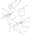
- the device according to the invention is shown in principle in the accompanying drawing.
- the accompanying drawing shows the basic structure of the device according to the invention, which consists of a receiving unit 1, is designed with corresponding receiving and clamping devices in which the spectacle lens 2 and the prescription lens 3 can be used and are preferably clamped using the blockers provided.
- the receiving units 1 for the spectacle lens 2 and the presentation glass 3 have a common axis of rotation 4, can be pivoted via their center points 5 and are connected to one another via a fixed coupling 6.
- the video camera 7 belonging to the device and the drilling unit 9 are firmly positioned in the device and connected to one another by means of a fixed coupling 8.
- the drilling unit 9 and the video camera 7 are mounted in the device in such a way that they can be moved vertically.
- the design of the receiving unit 1 ensures that the original lens 3 and the spectacle lens 2 can be pivoted about their common axis of rotation 4, which means that pivoting of the receiving unit 1 also pivots the original lens 3 and the spectacle lens 2, which applies analogously for the method of the recording unit 1. This means that every change in position of the recording unit 1 is transferred to the presentation glass 3 and the spectacle lens 2, and thus the positioning glass 3 is positioned precisely with respect to the video camera 7.
- the position of the bore of the reference glass 3 is detected in the sighting point 10, and as a result of the fixed coupling 8 between the video camera 7 and the drilling unit 9, the targeted position, the sighting point 10, the bore of the reference glass 3 is at the drilling point or else Transfer milling point 11 of the spectacle lens 2, so that when the drilling unit 9 is started up, a bore is made in the spectacle lens 3 which is congruent with the bore in the reference glass 3.
- the introduction of the bore into the spectacle lens 2, namely perpendicular to the plane of the spectacle lens, is ensured in that the entire receiving unit 1 and thus also the reference glass 3 and the spectacle lens 2 are pivoted in such a way that right angles 12 between the axes of the holes in the reference glass 3 and the spectacle lens 2 to the tangent plane 13 of the curvature of the respective lens.
Landscapes
- Engineering & Computer Science (AREA)
- Mechanical Engineering (AREA)
- Physics & Mathematics (AREA)
- Optics & Photonics (AREA)
- Mining & Mineral Resources (AREA)
- Eyeglasses (AREA)
- Re-Forming, After-Treatment, Cutting And Transporting Of Glass Products (AREA)
- Drilling And Boring (AREA)
- Perforating, Stamping-Out Or Severing By Means Other Than Cutting (AREA)
Applications Claiming Priority (2)
| Application Number | Priority Date | Filing Date | Title |
|---|---|---|---|
| DE10300190 | 2003-01-08 | ||
| DE10300190 | 2003-01-08 |
Publications (3)
| Publication Number | Publication Date |
|---|---|
| EP1437206A2 true EP1437206A2 (fr) | 2004-07-14 |
| EP1437206A3 EP1437206A3 (fr) | 2004-12-08 |
| EP1437206B1 EP1437206B1 (fr) | 2006-07-12 |
Family
ID=32478155
Family Applications (1)
| Application Number | Title | Priority Date | Filing Date |
|---|---|---|---|
| EP04000185A Expired - Lifetime EP1437206B1 (fr) | 2003-01-08 | 2004-01-07 | Dispositif de perçage de verres de lunettes |
Country Status (3)
| Country | Link |
|---|---|
| EP (1) | EP1437206B1 (fr) |
| AT (1) | ATE332790T1 (fr) |
| DE (2) | DE502004000932D1 (fr) |
Cited By (1)
| Publication number | Priority date | Publication date | Assignee | Title |
|---|---|---|---|---|
| EP2345520A1 (fr) * | 2010-01-14 | 2011-07-20 | Hans-Joachim Ollendorf | Dispositif de forage et de fraisage de verres de lunettes |
Family Cites Families (5)
| Publication number | Priority date | Publication date | Assignee | Title |
|---|---|---|---|---|
| GB1108457A (en) * | 1966-08-22 | 1968-04-03 | Ruth Bartlett Marantette | Two axis photoelectric positioning system |
| AU4699293A (en) * | 1992-08-17 | 1994-03-15 | Jan Houmand | Marking jig for spectacle lenses |
| DE4438634A1 (de) * | 1994-10-28 | 1996-05-09 | Rodenstock Optik G | Brillenglasbohrschablone |
| JP3687998B2 (ja) * | 1994-12-12 | 2005-08-24 | 株式会社トプコン | リムレスレンズの部品取付用の取付穴あけ装置 |
| DE19804428A1 (de) * | 1998-02-05 | 1999-08-19 | Wernicke & Co Gmbh | Verfahren zum Markieren oder Bohren von Löchern in Brillengläsern und Vorrichtung zur Durchführung des Verfahrens |
-
2004
- 2004-01-07 AT AT04000185T patent/ATE332790T1/de not_active IP Right Cessation
- 2004-01-07 DE DE502004000932T patent/DE502004000932D1/de not_active Expired - Lifetime
- 2004-01-07 EP EP04000185A patent/EP1437206B1/fr not_active Expired - Lifetime
- 2004-01-07 DE DE102004001304A patent/DE102004001304B4/de not_active Expired - Fee Related
Cited By (1)
| Publication number | Priority date | Publication date | Assignee | Title |
|---|---|---|---|---|
| EP2345520A1 (fr) * | 2010-01-14 | 2011-07-20 | Hans-Joachim Ollendorf | Dispositif de forage et de fraisage de verres de lunettes |
Also Published As
| Publication number | Publication date |
|---|---|
| DE502004000932D1 (de) | 2006-08-24 |
| EP1437206A3 (fr) | 2004-12-08 |
| DE102004001304A1 (de) | 2004-08-12 |
| ATE332790T1 (de) | 2006-08-15 |
| EP1437206B1 (fr) | 2006-07-12 |
| DE102004001304B4 (de) | 2006-09-28 |
Similar Documents
| Publication | Publication Date | Title |
|---|---|---|
| DE102011008663A1 (de) | Einrichtung zum Bohren und Fräsen von Brillengläsern | |
| DE102011089704B4 (de) | Verfahren zum Speichern von Information auf einem Brillenglas, als Brillenglas-Rohling oder Brillenglas-Halbfabrikat ausgebildeter Glas- oder Kunststoffkörper, Vorrichtung für das Speichern von Information, Verfahren zum Auslesen sowie Lesegerät | |
| EP1053075B2 (fr) | Procede pour marquer ou percer des trous dans des verres de lunettes et dispositif permettant de mettre ledit procede en oeuvre | |
| EP1436119A1 (fr) | Dispositif et procede pour l'usinage complet de lentilles optiquement actives sur les deux faces | |
| DE19701312A1 (de) | Brillenglas mit sphärischer Vorderseite und multifokaler Rückseite, sowie Verfahren zu seiner Herstellung | |
| DE102007037730B4 (de) | Brillenglas, Verfahren zu dessen Herstellung und Verfahren zu dessen Positionierung | |
| DE102009004380A1 (de) | Verfahren zum Herstellen einer individuellen Brillenfassung, Computerprogrammprodukt, Verwendung und Brillenfassungsherstellungsgerät | |
| DE4003002A1 (de) | Verfahren zur herstellung eines brillenglases und aufnahmeadapter fuer ein brillenglas | |
| DE102006026524A1 (de) | Maschine zur Bearbeitung von optischen Werkstücken, insbesondere von Kunststoff-Brillengläsern | |
| EP1581364B1 (fr) | Procede de centrage sans parallaxe d'un element optique | |
| DE102004001304B4 (de) | Einrichtung zum Bohren von Brillengläsern | |
| DE10151138B4 (de) | Asphärisches Einstärken-Brillenglas und Verfahren zu dessen Bearbeitung | |
| EP1450201A1 (fr) | Dispositif pour déterminer l'écart pupillaire | |
| DE19749631C2 (de) | Schablone für ein Brillenglas | |
| EP1862258B1 (fr) | Méthode pour la vérification de la précision d'une fixation de support d'objectif | |
| WO2012069168A2 (fr) | Dispositif et procédé pour usiner une lentille optique | |
| DE19920925C1 (de) | Randlose Brille mit an den Brillengläsern angeschraubten Bügeln und Nasensteg, und Verwendung einer Brillenglasrandbearbeitungsmaschine zum Herstellen von Langlöchern in Brillengläsern | |
| AT919U1 (de) | Brillenglasbohrschablone | |
| DE19954761A1 (de) | Halter für einen Block oder Sauger | |
| DE102018125092B4 (de) | Verfahren und Vorrichtung zum Markieren eines Brillenglases, Brillenglas-Rohlings oder Brillenglas-Halbfabrikats sowie Computerprogrammprodukt | |
| DE19749428A1 (de) | Bearbeitungsvorrichtung für die 3D-Bearbeitung von optischen Glasrohlingen | |
| DE102007063866B3 (de) | Brillenglas und Verfahren | |
| DE19752729A1 (de) | Verfahren und Vorrichtung zum Herstellen von Brillen | |
| DE202007019461U1 (de) | Brillenglas | |
| DE102007063787B3 (de) | Brillenglas sowie Verfahren zu dessen Herstellung |
Legal Events
| Date | Code | Title | Description |
|---|---|---|---|
| PUAI | Public reference made under article 153(3) epc to a published international application that has entered the european phase |
Free format text: ORIGINAL CODE: 0009012 |
|
| AK | Designated contracting states |
Kind code of ref document: A2 Designated state(s): AT BE BG CH CY CZ DE DK EE ES FI FR GB GR HU IE IT LI LU MC NL PT RO SE SI SK TR |
|
| AX | Request for extension of the european patent |
Extension state: AL LT LV MK |
|
| PUAL | Search report despatched |
Free format text: ORIGINAL CODE: 0009013 |
|
| AK | Designated contracting states |
Kind code of ref document: A3 Designated state(s): AT BE BG CH CY CZ DE DK EE ES FI FR GB GR HU IE IT LI LU MC NL PT RO SE SI SK TR |
|
| AX | Request for extension of the european patent |
Extension state: AL LT LV MK |
|
| RIC1 | Information provided on ipc code assigned before grant |
Ipc: 7B 28D 1/14 A Ipc: 7B 23Q 35/02 B Ipc: 7B 23Q 35/128 B |
|
| 17P | Request for examination filed |
Effective date: 20050531 |
|
| AKX | Designation fees paid |
Designated state(s): AT BE BG CH CY CZ DE DK EE ES FI FR GB GR HU IE IT LI LU MC NL PT RO SE SI SK TR |
|
| GRAP | Despatch of communication of intention to grant a patent |
Free format text: ORIGINAL CODE: EPIDOSNIGR1 |
|
| GRAF | Information related to payment of grant fee modified |
Free format text: ORIGINAL CODE: EPIDOSCIGR3 |
|
| GRAS | Grant fee paid |
Free format text: ORIGINAL CODE: EPIDOSNIGR3 |
|
| GRAA | (expected) grant |
Free format text: ORIGINAL CODE: 0009210 |
|
| AK | Designated contracting states |
Kind code of ref document: B1 Designated state(s): AT BE BG CH CY CZ DE DK EE ES FI FR GB GR HU IE IT LI LU MC NL PT RO SE SI SK TR |
|
| PG25 | Lapsed in a contracting state [announced via postgrant information from national office to epo] |
Ref country code: IT Free format text: LAPSE BECAUSE OF FAILURE TO SUBMIT A TRANSLATION OF THE DESCRIPTION OR TO PAY THE FEE WITHIN THE PRESCRIBED TIME-LIMIT;WARNING: LAPSES OF ITALIAN PATENTS WITH EFFECTIVE DATE BEFORE 2007 MAY HAVE OCCURRED AT ANY TIME BEFORE 2007. THE CORRECT EFFECTIVE DATE MAY BE DIFFERENT FROM THE ONE RECORDED. Effective date: 20060712 Ref country code: IE Free format text: LAPSE BECAUSE OF FAILURE TO SUBMIT A TRANSLATION OF THE DESCRIPTION OR TO PAY THE FEE WITHIN THE PRESCRIBED TIME-LIMIT Effective date: 20060712 Ref country code: CZ Free format text: LAPSE BECAUSE OF FAILURE TO SUBMIT A TRANSLATION OF THE DESCRIPTION OR TO PAY THE FEE WITHIN THE PRESCRIBED TIME-LIMIT Effective date: 20060712 Ref country code: GB Free format text: LAPSE BECAUSE OF FAILURE TO SUBMIT A TRANSLATION OF THE DESCRIPTION OR TO PAY THE FEE WITHIN THE PRESCRIBED TIME-LIMIT Effective date: 20060712 Ref country code: SI Free format text: LAPSE BECAUSE OF FAILURE TO SUBMIT A TRANSLATION OF THE DESCRIPTION OR TO PAY THE FEE WITHIN THE PRESCRIBED TIME-LIMIT Effective date: 20060712 Ref country code: FI Free format text: LAPSE BECAUSE OF FAILURE TO SUBMIT A TRANSLATION OF THE DESCRIPTION OR TO PAY THE FEE WITHIN THE PRESCRIBED TIME-LIMIT Effective date: 20060712 Ref country code: RO Free format text: LAPSE BECAUSE OF FAILURE TO SUBMIT A TRANSLATION OF THE DESCRIPTION OR TO PAY THE FEE WITHIN THE PRESCRIBED TIME-LIMIT Effective date: 20060712 Ref country code: NL Free format text: LAPSE BECAUSE OF FAILURE TO SUBMIT A TRANSLATION OF THE DESCRIPTION OR TO PAY THE FEE WITHIN THE PRESCRIBED TIME-LIMIT Effective date: 20060712 Ref country code: SK Free format text: LAPSE BECAUSE OF FAILURE TO SUBMIT A TRANSLATION OF THE DESCRIPTION OR TO PAY THE FEE WITHIN THE PRESCRIBED TIME-LIMIT Effective date: 20060712 |
|
| REG | Reference to a national code |
Ref country code: GB Ref legal event code: FG4D Free format text: NOT ENGLISH |
|
| REG | Reference to a national code |
Ref country code: CH Ref legal event code: EP |
|
| REG | Reference to a national code |
Ref country code: IE Ref legal event code: FG4D Free format text: LANGUAGE OF EP DOCUMENT: GERMAN |
|
| REF | Corresponds to: |
Ref document number: 502004000932 Country of ref document: DE Date of ref document: 20060824 Kind code of ref document: P |
|
| PG25 | Lapsed in a contracting state [announced via postgrant information from national office to epo] |
Ref country code: DK Free format text: LAPSE BECAUSE OF FAILURE TO SUBMIT A TRANSLATION OF THE DESCRIPTION OR TO PAY THE FEE WITHIN THE PRESCRIBED TIME-LIMIT Effective date: 20061012 Ref country code: SE Free format text: LAPSE BECAUSE OF FAILURE TO SUBMIT A TRANSLATION OF THE DESCRIPTION OR TO PAY THE FEE WITHIN THE PRESCRIBED TIME-LIMIT Effective date: 20061012 Ref country code: BG Free format text: LAPSE BECAUSE OF FAILURE TO SUBMIT A TRANSLATION OF THE DESCRIPTION OR TO PAY THE FEE WITHIN THE PRESCRIBED TIME-LIMIT Effective date: 20061012 |
|
| PG25 | Lapsed in a contracting state [announced via postgrant information from national office to epo] |
Ref country code: ES Free format text: LAPSE BECAUSE OF FAILURE TO SUBMIT A TRANSLATION OF THE DESCRIPTION OR TO PAY THE FEE WITHIN THE PRESCRIBED TIME-LIMIT Effective date: 20061023 |
|
| PG25 | Lapsed in a contracting state [announced via postgrant information from national office to epo] |
Ref country code: PT Free format text: LAPSE BECAUSE OF FAILURE TO SUBMIT A TRANSLATION OF THE DESCRIPTION OR TO PAY THE FEE WITHIN THE PRESCRIBED TIME-LIMIT Effective date: 20061212 |
|
| NLV1 | Nl: lapsed or annulled due to failure to fulfill the requirements of art. 29p and 29m of the patents act | ||
| PG25 | Lapsed in a contracting state [announced via postgrant information from national office to epo] |
Ref country code: MC Free format text: LAPSE BECAUSE OF NON-PAYMENT OF DUE FEES Effective date: 20070131 |
|
| GBV | Gb: ep patent (uk) treated as always having been void in accordance with gb section 77(7)/1977 [no translation filed] |
Effective date: 20060712 |
|
| REG | Reference to a national code |
Ref country code: IE Ref legal event code: FD4D |
|
| ET | Fr: translation filed | ||
| PLBE | No opposition filed within time limit |
Free format text: ORIGINAL CODE: 0009261 |
|
| STAA | Information on the status of an ep patent application or granted ep patent |
Free format text: STATUS: NO OPPOSITION FILED WITHIN TIME LIMIT |
|
| 26N | No opposition filed |
Effective date: 20070413 |
|
| BERE | Be: lapsed |
Owner name: OLLENDORF, HANS-JOACHIM Effective date: 20070131 |
|
| PG25 | Lapsed in a contracting state [announced via postgrant information from national office to epo] |
Ref country code: BE Free format text: LAPSE BECAUSE OF NON-PAYMENT OF DUE FEES Effective date: 20070131 |
|
| PG25 | Lapsed in a contracting state [announced via postgrant information from national office to epo] |
Ref country code: GR Free format text: LAPSE BECAUSE OF FAILURE TO SUBMIT A TRANSLATION OF THE DESCRIPTION OR TO PAY THE FEE WITHIN THE PRESCRIBED TIME-LIMIT Effective date: 20061013 |
|
| PG25 | Lapsed in a contracting state [announced via postgrant information from national office to epo] |
Ref country code: AT Free format text: LAPSE BECAUSE OF NON-PAYMENT OF DUE FEES Effective date: 20070107 |
|
| PG25 | Lapsed in a contracting state [announced via postgrant information from national office to epo] |
Ref country code: EE Free format text: LAPSE BECAUSE OF FAILURE TO SUBMIT A TRANSLATION OF THE DESCRIPTION OR TO PAY THE FEE WITHIN THE PRESCRIBED TIME-LIMIT Effective date: 20060712 |
|
| REG | Reference to a national code |
Ref country code: CH Ref legal event code: PL |
|
| PG25 | Lapsed in a contracting state [announced via postgrant information from national office to epo] |
Ref country code: LI Free format text: LAPSE BECAUSE OF NON-PAYMENT OF DUE FEES Effective date: 20080131 Ref country code: CH Free format text: LAPSE BECAUSE OF NON-PAYMENT OF DUE FEES Effective date: 20080131 |
|
| PG25 | Lapsed in a contracting state [announced via postgrant information from national office to epo] |
Ref country code: LU Free format text: LAPSE BECAUSE OF NON-PAYMENT OF DUE FEES Effective date: 20070107 Ref country code: CY Free format text: LAPSE BECAUSE OF FAILURE TO SUBMIT A TRANSLATION OF THE DESCRIPTION OR TO PAY THE FEE WITHIN THE PRESCRIBED TIME-LIMIT Effective date: 20060712 |
|
| PG25 | Lapsed in a contracting state [announced via postgrant information from national office to epo] |
Ref country code: HU Free format text: LAPSE BECAUSE OF FAILURE TO SUBMIT A TRANSLATION OF THE DESCRIPTION OR TO PAY THE FEE WITHIN THE PRESCRIBED TIME-LIMIT Effective date: 20070113 Ref country code: TR Free format text: LAPSE BECAUSE OF FAILURE TO SUBMIT A TRANSLATION OF THE DESCRIPTION OR TO PAY THE FEE WITHIN THE PRESCRIBED TIME-LIMIT Effective date: 20060712 |
|
| PGFP | Annual fee paid to national office [announced via postgrant information from national office to epo] |
Ref country code: FR Payment date: 20130207 Year of fee payment: 10 Ref country code: DE Payment date: 20130107 Year of fee payment: 10 |
|
| REG | Reference to a national code |
Ref country code: DE Ref legal event code: R119 Ref document number: 502004000932 Country of ref document: DE |
|
| PG25 | Lapsed in a contracting state [announced via postgrant information from national office to epo] |
Ref country code: DE Free format text: LAPSE BECAUSE OF NON-PAYMENT OF DUE FEES Effective date: 20140801 |
|
| REG | Reference to a national code |
Ref country code: FR Ref legal event code: ST Effective date: 20140930 |
|
| REG | Reference to a national code |
Ref country code: DE Ref legal event code: R119 Ref document number: 502004000932 Country of ref document: DE Effective date: 20140801 |
|
| PG25 | Lapsed in a contracting state [announced via postgrant information from national office to epo] |
Ref country code: FR Free format text: LAPSE BECAUSE OF NON-PAYMENT OF DUE FEES Effective date: 20140131 |