EP1437223A2 - Ink-jet recording head - Google Patents
Ink-jet recording head Download PDFInfo
- Publication number
- EP1437223A2 EP1437223A2 EP03029989A EP03029989A EP1437223A2 EP 1437223 A2 EP1437223 A2 EP 1437223A2 EP 03029989 A EP03029989 A EP 03029989A EP 03029989 A EP03029989 A EP 03029989A EP 1437223 A2 EP1437223 A2 EP 1437223A2
- Authority
- EP
- European Patent Office
- Prior art keywords
- discharge
- port portion
- ink
- port
- facing
- Prior art date
- Legal status (The legal status is an assumption and is not a legal conclusion. Google has not performed a legal analysis and makes no representation as to the accuracy of the status listed.)
- Granted
Links
Images




Classifications
-
- B—PERFORMING OPERATIONS; TRANSPORTING
- B41—PRINTING; LINING MACHINES; TYPEWRITERS; STAMPS
- B41J—TYPEWRITERS; SELECTIVE PRINTING MECHANISMS, i.e. MECHANISMS PRINTING OTHERWISE THAN FROM A FORME; CORRECTION OF TYPOGRAPHICAL ERRORS
- B41J2/00—Typewriters or selective printing mechanisms characterised by the printing or marking process for which they are designed
- B41J2/005—Typewriters or selective printing mechanisms characterised by the printing or marking process for which they are designed characterised by bringing liquid or particles selectively into contact with a printing material
- B41J2/01—Ink jet
- B41J2/135—Nozzles
- B41J2/14—Structure thereof only for on-demand ink jet heads
- B41J2/14016—Structure of bubble jet print heads
- B41J2/14032—Structure of the pressure chamber
- B41J2/1404—Geometrical characteristics
-
- B—PERFORMING OPERATIONS; TRANSPORTING
- B41—PRINTING; LINING MACHINES; TYPEWRITERS; STAMPS
- B41J—TYPEWRITERS; SELECTIVE PRINTING MECHANISMS, i.e. MECHANISMS PRINTING OTHERWISE THAN FROM A FORME; CORRECTION OF TYPOGRAPHICAL ERRORS
- B41J2/00—Typewriters or selective printing mechanisms characterised by the printing or marking process for which they are designed
- B41J2/005—Typewriters or selective printing mechanisms characterised by the printing or marking process for which they are designed characterised by bringing liquid or particles selectively into contact with a printing material
- B41J2/01—Ink jet
- B41J2/135—Nozzles
- B41J2/14—Structure thereof only for on-demand ink jet heads
- B41J2/1433—Structure of nozzle plates
-
- B—PERFORMING OPERATIONS; TRANSPORTING
- B41—PRINTING; LINING MACHINES; TYPEWRITERS; STAMPS
- B41J—TYPEWRITERS; SELECTIVE PRINTING MECHANISMS, i.e. MECHANISMS PRINTING OTHERWISE THAN FROM A FORME; CORRECTION OF TYPOGRAPHICAL ERRORS
- B41J2/00—Typewriters or selective printing mechanisms characterised by the printing or marking process for which they are designed
- B41J2/005—Typewriters or selective printing mechanisms characterised by the printing or marking process for which they are designed characterised by bringing liquid or particles selectively into contact with a printing material
- B41J2/01—Ink jet
- B41J2/135—Nozzles
- B41J2/145—Arrangement thereof
-
- B—PERFORMING OPERATIONS; TRANSPORTING
- B41—PRINTING; LINING MACHINES; TYPEWRITERS; STAMPS
- B41J—TYPEWRITERS; SELECTIVE PRINTING MECHANISMS, i.e. MECHANISMS PRINTING OTHERWISE THAN FROM A FORME; CORRECTION OF TYPOGRAPHICAL ERRORS
- B41J2/00—Typewriters or selective printing mechanisms characterised by the printing or marking process for which they are designed
- B41J2/005—Typewriters or selective printing mechanisms characterised by the printing or marking process for which they are designed characterised by bringing liquid or particles selectively into contact with a printing material
- B41J2/01—Ink jet
- B41J2/135—Nozzles
- B41J2/14—Structure thereof only for on-demand ink jet heads
- B41J2002/14387—Front shooter
-
- B—PERFORMING OPERATIONS; TRANSPORTING
- B41—PRINTING; LINING MACHINES; TYPEWRITERS; STAMPS
- B41J—TYPEWRITERS; SELECTIVE PRINTING MECHANISMS, i.e. MECHANISMS PRINTING OTHERWISE THAN FROM A FORME; CORRECTION OF TYPOGRAPHICAL ERRORS
- B41J2/00—Typewriters or selective printing mechanisms characterised by the printing or marking process for which they are designed
- B41J2/005—Typewriters or selective printing mechanisms characterised by the printing or marking process for which they are designed characterised by bringing liquid or particles selectively into contact with a printing material
- B41J2/01—Ink jet
- B41J2/135—Nozzles
- B41J2/14—Structure thereof only for on-demand ink jet heads
- B41J2002/14403—Structure thereof only for on-demand ink jet heads including a filter
-
- B—PERFORMING OPERATIONS; TRANSPORTING
- B41—PRINTING; LINING MACHINES; TYPEWRITERS; STAMPS
- B41J—TYPEWRITERS; SELECTIVE PRINTING MECHANISMS, i.e. MECHANISMS PRINTING OTHERWISE THAN FROM A FORME; CORRECTION OF TYPOGRAPHICAL ERRORS
- B41J2/00—Typewriters or selective printing mechanisms characterised by the printing or marking process for which they are designed
- B41J2/005—Typewriters or selective printing mechanisms characterised by the printing or marking process for which they are designed characterised by bringing liquid or particles selectively into contact with a printing material
- B41J2/01—Ink jet
- B41J2/135—Nozzles
- B41J2/14—Structure thereof only for on-demand ink jet heads
- B41J2002/14467—Multiple feed channels per ink chamber
-
- B—PERFORMING OPERATIONS; TRANSPORTING
- B41—PRINTING; LINING MACHINES; TYPEWRITERS; STAMPS
- B41J—TYPEWRITERS; SELECTIVE PRINTING MECHANISMS, i.e. MECHANISMS PRINTING OTHERWISE THAN FROM A FORME; CORRECTION OF TYPOGRAPHICAL ERRORS
- B41J2/00—Typewriters or selective printing mechanisms characterised by the printing or marking process for which they are designed
- B41J2/005—Typewriters or selective printing mechanisms characterised by the printing or marking process for which they are designed characterised by bringing liquid or particles selectively into contact with a printing material
- B41J2/01—Ink jet
- B41J2/135—Nozzles
- B41J2/14—Structure thereof only for on-demand ink jet heads
- B41J2002/14475—Structure thereof only for on-demand ink jet heads characterised by nozzle shapes or number of orifices per chamber
Definitions
- the present invention relates to a liquid-discharge head for performing recording on a recording medium by discharging droplets of a liquid, such as ink, or the like. More particularly, the invention relates to a liquid discharge head for performing ink-jet recording.
- An ink-jet recording method is one of so-called non-impact recording methods.
- noise generated during recording is negligibly small, and high-speed recording can be performed.
- recording can be performed on various recording media.
- ink is fixed without requiring particular processing, and a very precise image can be inexpensively obtained. Because of such features, the ink-jet recording method has been rapidly diffused recently not only for printers, serving as peripheral apparatuses of computers, but also as recording means for copiers, facsimile apparatuses, word processors, and the like.
- Generally utilized ink discharge methods of the ink-jet recording method includes a method of using electrothermal transducers, such as heaters or the like, as discharge-energy generation elements used for discharging ink droplets, and a method of using piezoelectric elements.
- electrothermal transducers such as heaters or the like
- piezoelectric elements Each of these methods can control discharge of ink droplets by an electric signal.
- the principle of the ink discharge method using electrothermal transducers consists in causing ink near an electrothermal transducer to instantaneously boil by applying a voltage to the electrothermal transducer, and discharging an ink droplet at a high speed by an abrupt bubble pressure generated by a phase change of ink at boiling.
- the method of discharging ink using piezoelectric elements consists in discharging ink droplets by a pressure generated during displacement of a piezoelectric element caused by application of a voltage to the piezoelectric element.
- the ink discharge method using electrothermal transducers has, for example, the features that it is unnecessary to provide a large space for disposing discharge-energy generation elements, the structure of a recording head is simple, and nozzles can be easily integrated.
- this method has, for example, the peculiar problems that the volume of a traveling ink droplet changes due to storage of heat generated by the electrothermal transducers within the recording head, cavitation produced by disappearance of a bubble adversely influences the electrothermal transducers, and the discharge characteristics of ink droplets and the image quality are adversely influenced by a bubble of air dissolved within ink that remains within the recording head.
- Japanese Patent Application Laid-Open (Kokai) Nos. 54-161935 (1979), 61-185455 (1986), 61-249768 (1986) and 4-10941 1992) disclose ink-jet recording methods and recording heads.
- a bubble generated by driving an electrothermal transducer is caused to communicate with external air.
- the configuration of a recording head of this type includes an element substrate where electrothermal transducers for discharging ink, and a channel-configuration substrate (also termed an "orifice substrate") for providing ink channels by being connected to the element substrate.
- the channel-configuration substrate includes a plurality of nozzles where ink flows, a supply chamber for supplying these nozzles with ink, and a plurality of discharge ports, serving as nozzle-distal-end openings for discharging ink droplets.
- the nozzle includes a bubble generation chamber for generating a bubble by a corresponding one of the electrothermal transducers, and a supply channel for supplying the bubble generation chamber with ink.
- the element substrate includes the electrothermal transducers at positions corresponding to the bubble generation chambers.
- the element substrate also includes a supply port for supplying the supply chamber with ink from a back surface opposite to a main surface contacting the channel-configuration substrate.
- the channel-configuration substrate includes discharge ports at positions facing corresponding ones of the electrothermal transducers on the element substrate.
- ink supplied from the supply port into the supply chamber is supplied along each of the nozzles, and is filled within the bubble generation chamber.
- the ink filled within the bubble generation chamber is caused to travel in a direction substantially orthogonal to the main surface of the element substrate by a bubble generated by film boiling by the electrothermal transducer, and is discharged from the discharge port as an ink droplet (a head of this type is hereinafter termed a "side-shooter-type ink-jet head").
- ink filled within the bubble generation chamber travels separately toward the discharge port side and the supply channel side due to a bubble generated within the bubble generation chamber. At that time, part of a pressure due to bubble generation in the ink is applied toward the supply channel side, or a pressure loss is generated due to friction with the inner wall of the discharge port. This phenomenon adversely influences ink discharge, and is more pronounced as the amount of the discharged ink droplet is smaller (as the volume of the discharged droplet is smaller).
- the fluid resistance of the discharge port greatly increases to reduce the flow rate toward the discharge port and increase the flow rate toward the supply channel, thereby reducing the discharge speed of the ink droplet.
- an ink-jet recording head includes a channel-configuration substrate including a plurality of discharge ports for discharging a liquid, a plurality of bubble generation chambers for generating bubbles utilized for discharging the liquid by thermal energy generated by electrothermal transducers, a plurality of discharge-port portions for causing the discharge ports to communicate with the bubble generation chambers, and at least one supply channel for supplying the discharge-port portions and the bubble generation chambers with the liquid, and an element substrate on which the electrothermal transducers are provided, and to a main surface of which the channel-configuration substrate is connected.
- Each of the discharge-port portions includes a first discharge-port portion continuing from one of the discharge ports, and a second discharge-port portion for causing the first discharge-port portion to communicate with one of the bubble generation chambers.
- the second discharge-port portion has an end surface that includes a border portion with the first discharge-port portion and is parallel to the main surface of the element substrate. An area of a cross section of the second discharge-port portion that is parallel to the main surface of the element substrate is larger than an area of the border portion at any cross section of the second discharge-port portion from an opening surface facing the bubble generation chamber to the end surface facing the first discharge-port portion.
- a cross section of the opening surface of the second discharge-port portion facing the bubble generation chamber that is parallel to the main surface of the element substrate has a shape such that a length in a direction perpendicular to a direction of arrangement of the discharge ports is larger than a length in a direction parallel to the direction of arrangement of the discharge ports.
- an ink-jet recording head includes a channel-configuration substrate including a plurality of discharge ports for discharging a liquid, a plurality of pressure chambers for generating pressures utilized for discharging the liquid by discharge-energy generation elements, a plurality of discharge-port portions for causing the discharge ports to communicate with the pressure chambers, and at least one supply channel for supplying the discharge-port portion and the pressure chamber with the liquid, and an element substrate on which the discharge-energy generation elements are provided, and to a main surface of which the channel-configuration substrate is connected.
- Each of the discharge-port portions includes a first discharge-port portion continuing from one of the discharge ports, and a second discharge-port portion for causing the first discharge-port portion to communicate with one of the pressure chambers.
- the second discharge-port portion has an end surface that includes a border portion with the first discharge-port portion and is parallel to the main surface of the element substrate.
- An area of a cross section of the second discharge-port portion that is parallel to the main surface of the element substrate is larger than an area of the border portion at any cross section of the second discharge-port portion from an opening surface facing the pressure chamber to the end surface facing the first discharge-port portion.
- a cross section of the opening surface of the second discharge-port portion facing the pressure chamber that is parallel to the main surface of the element substrate has a shape such that a length in a direction perpendicular to a direction of arrangement of the discharge ports is larger than a length in a direction parallel to the direction of arrangement of the discharge ports.
- a cross section of the second discharge-port portion at the end surface facing the first discharge-port portion has a shape such that a ratio of a length of the second discharge-port portion to a length of the first discharge-port portion in the direction perpendicular to the direction of arrangement of the discharge ports is larger than a ratio of a length of the second discharge-port portion to a length of the first discharge-port portion in the direction parallel to the direction of arrangement of the discharge ports.
- a pressure loss in the flow of the liquid toward the discharge ports can be minimized.
- the fluid resistance in the direction of the discharge ports at the first discharge-port portion is increased by further reducing the size of the discharge ports at distal ends of nozzles, it is possible to suppress reduction of the flow rate in the direction of the discharge ports when discharging the liquid, and prevent reduction in the discharge speed of a liquid droplet.
- An ink discharge method in which a bubble generated by the discharge-energy generation element communicates with external air is suitably applied to the ink-jet recording head of the present invention.
- An ink-jet recording head adopts a method, from among various ink-jet recording methods, in which means for generating thermal energy utilized for discharging ink in the form of a liquid is provided, and a change in the state of the ink is caused to occur by the thermal energy.
- a change in the state of the ink is caused to occur by the thermal energy.
- characters, images and the like are recorded very precisely at a high density.
- an electrothermal transducer is used as means for generating thermal energy, and ink is discharged utilizing a pressure due to a bubble generated when ink is subjected to film boiling by being heated
- FIG. 1 is a partly broken perspective view illustrating the ink-jet recording head of the invention.
- a partition wall for individually forming nozzles 5, each serving as an ink channel, for a plurality of heaters 1, each serving as an electrothermal transducer, is extended from a first discharge-port portion 4 to a portion near a supply chamber 6.
- the ink-jet recording head has the plurality of heaters 2 and the plurality of nozzles 5, and has a first nozzle row in which the longitudinal direction of each of the nozzles 5 is arranged in parallel, and a second nozzle row 8 in which the longitudinal direction of each of the nozzles 5 is arranged in parallel at a position facing the first nozzle row 7 across the supply chamber 6.
- nozzles are arranged at a pitch of 600 - 1,200 dpi (dots per inch).
- the nozzles 5 of the first nozzle row 8 are arranged by being shifted by a 1/2 pitch with respect to the nozzles 5 of the first nozzle row 7.
- This recording head has ink discharge means to which an ink-jet recording method disclosed in Japanese Patent Application Laid-Open (Kokai) Nos. 4-10940 (1992) and 4-10941 (1992) is applied, and can have a structure in which a bubble generated during ink discharge is caused to communicate with external air via a discharge port.
- the ink-jet recording head of the invention includes a channel-configuration substrate 3 that includes the plurality of nozzles 5 in which ink flows, the supply chamber 6 for supplying each of the nozzles 5 with ink, and the plurality of first discharge-port portion 4, each serving as a nozzle-distal-end opening for discharging an ink droplet.
- the nozzle 5 includes a discharge-port portion including the first discharge-port portion 4, a bubble generation chamber 11 for generating a bubble by thermal energy generated by the heater 1, serving as an electrothermal transducer, a second discharge-port portion 10 for causing the discharge-port portion to communicate with the bubble generation chamber 11, and a supply channel 9 for supplying the bubble generation chamber 11 with ink.
- the ink-jet recording head also includes an element substrate 2 on which the heaters 1 are provided, and to a main surface of which the channel-configuration substrate is connected.
- the second discharge-port portion 10 is connected to the first discharge-port portion 4 and the bubble generation chamber 11 with respective steps.
- the cross section of the second discharge-port portion 10 along a plane substantially parallel to the main surface of the element substrate 2 is outside of the cross section of the discharge port in the same direction and inside of the cross section of the bubble generation chamber 11 in the same direction.
- the second discharge-port portion 10 has an end surface that includes a border portion with the first discharge-port portion 4 and is parallel to the main surface (a surface where the channel-configuration substrate is connected) of the element substrate 2.
- An area of a cross section of the second discharge-port portion 10 that is parallel to the main surface of the element substrate 2 is larger than an area of the border portion (an opening surface of the first discharge-port portion 4 facing the second discharge-port portion 10) at any cross section from an opening surface facing the bubble generation chamber 11 to the end surface facing the first discharge-port portion 4.
- a cross section of the opening surface of the second discharge-port portion 10 facing the bubble generation chamber 11 that is parallel to the main surface of the element substrate 2 has a shape such that a length in a direction perpendicular to a direction of arrangement of the discharge ports is larger than a length in a direction parallel to the direction of arrangement of the discharge ports.
- the size of the nozzle In order to reduce the amount of a discharged ink droplet (reduce the volume of the ink droplet), the size of the nozzle must be reduced. In this case, the fluid resistance of the supply channel greatly increases. As a result, the time required for refilling increases than before the size of the nozzle is reduced.
- By providing two ink supply channels facing across a heating resistor it is possible to reduce the total fluid resistance of the ink supply channel, and shorten the time required for refilling.
- the configuration of the present invention is preferable.
- the bubble pressure When providing a heater in which the length in a direction perpendicular to the direction of arrangement of the discharge ports is larger than the length in a direction parallel to the direction of arrangement of the discharge ports, the bubble pressure has a spread in the direction perpendicular to the direction of arrangement of the discharge ports. Since the opening surface of the second discharge-port portion facing the bubble generation chamber is wide in the direction perpendicular to the direction of arrangement of the discharge ports, the bubble pressure having the spread can be sufficiently utilized as energy in the direction of ink discharge. Since the second discharge-port portion can be provided by being adjusted with the effective bubble area, the state of bubble generation can be more stabilized.
- FIGS. 2A - 2C illustrate the structure of a nozzle of an ink-jet recording head according to a first embodiment of the present invention.
- FIG. 2A is a plan perspective diagram in which one of a plurality of nozzles of the ink-jet recording head is seen from a direction perpendicular to a main surface (a surface where the channel-configuration substrate of the element substrate 2 is connected) of the element substrate 2;
- FIG. 2B is a cross-sectional view taken along line A - A shown in FIG. 2A;
- FIG. 2C is a cross-sectional view taken along line B - B shown in FIG. 2A.
- the recording head having the nozzle structure of the first embodiment includes the element substrate 2 on which the plurality of heaters 1, each serving as an electrothermal transducer, are provided, and the channel-configuration substrate 3 that constitutes a plurality of ink channels by being connected to the main surface of the element substrate 2 in a laminated state.
- the element substrate 2 is made of glass, ceramics, a resin, a metal, or the like. In general, the element substrate 2 is made of Si.
- the heater 1, electrodes (not shown) for applying a voltage to the heater 1, and wires (not shown) connected to the electrodes are provided for each of the ink channels with a predetermined wiring pattern.
- An insulating film (not shown) for improving the heat dispersion property is provided on the main surface of the element substrate 2 so as to cover the heaters 1.
- a protective film (not shown) for protecting the components from cavitation generated when a bubble disappears is provided so as to cover the insulating film.
- the channel configuration substrate 3 includes the plurality of nozzles 5 where ink flows, the supply chamber 6 for supplying the nozzles 5 with ink, and the plurality of first discharge-port portions 4, each serving as a distal-end opening of the nozzle 5 for discharging an ink droplet.
- the first discharge-port portions 4 are formed at positions facing the heaters 1 on the element substrate 2.
- the nozzle 5 has the first discharge-port portion 4 having a substantially constant diameter, the second discharge-port portion 10 for reducing the fluid resistance at the discharge port side, the bubble generation chamber 11, and the supply channel 9 (indicated by hatching in FIG. 2B).
- the bubble generation chamber 11 is formed on the heater 1 so that the base facing the opening surface of the first discharge-port portion 4 has a substantially rectangular shape.
- One end of the supply channel 9 communicates with the bubble generation chamber 11, and another end of the supply channel 9 communicates with the supply chamber 6.
- the supply channel 9 has a straight shape with a substantially constant width from the supply chamber 6 to the bubble generation chamber 11.
- the second discharge-port portion 10 is continuously formed above the bubble generation chamber 11.
- the nozzle 5 is formed such that the direction of discharge of an ink droplet from the first discharge-port portion 4 is orthogonal to the direction of flow of ink within the supply channel 9.
- the inner-wall surface facing the main surface of the element substrate 2 is parallel to the main surface of the element substrate 2 from the supply chamber 6 to the bubble generation chamber 11.
- the second discharge-port portion 10 has an end surface that includes a border portion with the first discharge-port portion 4 and is parallel to the main surface (a surface where the channel-configuration substrate 3 is connected) of the element substrate 2.
- the area of the end surface of the second discharge-port portion 10 facing the first discharge-port portion 4 is larger than the area of the border portion (an opening surface of the first discharge-port portion 4 facing the second discharge-port portion 10).
- the cross section of the opening surface of the second discharge-port portion 10 facing the bubble generation chamber 11 that is parallel to the main surface of the element substrate 2 has a shape such that the length in a direction perpendicular to a direction of arrangement of the first discharge-port portion 4 is larger than the length in a direction parallel to the direction of arrangement of the discharge-port portion 4.
- the end surface facing the first discharge-port portion 4 has the same cross section as the opening surface facing the bubble generation chamber 11.
- a cross section obtained by cutting the second discharge-port portion 10 along a plane substantially parallel to the surface where the heater 1 is formed is substantially rectangular.
- the second discharge-port portion 10 is made symmetrical with respect to the perpendicular drawn from the center of the first discharge-port portion 4 toward the main surface of the element substrate 2, to provide a well-balanced shape.
- the side wall of the second discharge-port portion 10 is represented by straight lines at any cross section passing through the center of the first discharge-port portion 4 and perpendicular to the main surface of the element substrate 2.
- the opening surfaces of the second discharge-port portion 10 facing the first discharge-port portion 4 and the bubble generation chamber 11, respectively, and the main surface of the element substrate 2 are substantially parallel.
- ink supplied into the supply chamber 6 is supplied to the respective nozzles 5 of the first nozzle row 7 and the second nozzle row 8.
- the ink supplied to each of the nozzles 5 is filled into the bubble generation chamber 11 by flowing along the supply channel 9.
- the ink filled within the bubble generation chamber 11 is discharged from the first discharge-port portion 4 as an ink droplet by the pressure of a growing bubble generated by film boiling caused by the heater 1.
- part of the ink within the bubble generation chamber 11 flows toward the supply channel 9 by the pressure of the bubble generated within the bubble generation chamber 11.
- the pressure of the bubble generated within the bubble generation chamber 11 is also transmitted to the second discharge-port portion 10 instantaneously, and ink filled in the bubble generation chamber 11 and the second discharge-port portion 10 moves within the second discharge-port portion 10.
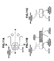
- the cross section of the second discharge-port portion 10 that is parallel to the main surface of the element substrate 2, i.e., the spatial volume, is larger than in the recording head shown in FIGS. 11A - 11C that has only the cylindrical first discharge-port portion 4 as the discharge-port portion without having the second discharge-port portion 10, a pressure loss is very small, and ink is excellently discharged toward the first discharge-port portion 4. Accordingly, even if the fluid resistance in the direction of the discharge port at the discharge-port portion increases by further reducing the discharge port at the distal end of the nozzle, it is possible to suppress reduction in the flow rate in the direction of the discharge port, and prevent a decrease in the discharge speed of the ink droplet.
- a nozzle structure is adopted in which the second discharge-port portion has a tapered shape in order to reduce stagnation of ink at the second discharge-port portion. Portions different from the first embodiment will now be mainly described with reference to FIGS. 3A - 3C.
- FIGS. 3A - 3C illustrate the structure of a nozzle of an ink-jet recording head according to the second embodiment.
- FIG. 3A is a plan perspective diagram in which one of a plurality of nozzles of the ink-jet recording head is seen from a direction perpendicular to the main surface of the element substrate 2;
- FIG. 3B is a cross-sectional view taken along line A-A shown in FIG. 3A;
- FIG. 3C is a cross-sectional view taken along line B - B shown in FIG. 3A.
- the second discharge-port portion 10 has an end surface that includes a border portion with the first discharge-port portion 4 and is parallel to the main surface (a surface where the channel-configuration substrate 3 is connected) of the element substrate 2.
- the area of the end surface of the second discharge-port portion 10 facing the first discharge-port portion 4 is larger than the area of the border portion (an opening surface of the first discharge-port portion 4 facing the second discharge-port portion 10).
- the cross section of the opening surface of the second discharge-port portion 10 facing the bubble generation chamber 11 that is parallel to the main surface of the element substrate 2 has a shape such that the length in a direction perpendicular to a direction of arrangement of the first discharge-port portion 4 is longer than the length in a direction parallel to the direction of arrangement of the discharge-port portion 4.
- the end surface facing the discharge first discharge-port portion 4 is similar to and has a smaller cross section than the opening surface facing the bubble generation chamber 11.
- a cross section obtained by cutting the second discharge-port portion 10 along a plane substantially parallel to the surface where the heater 1 is formed is substantially rectangular.
- the cross section of the second discharge-port portion 10 parallel to the main surface of the element substrate 2, i.e., the spatial volume, is larger than the border portion between the first discharge-port portion 4 and the second discharge-port portion 10 compared with the recording head shown in FIGS. 11A - 11C in which the discharge-port portion 4 within the nozzle is cylindrical, a pressure loss is very small, and ink is excellently discharged toward the first discharge-port portion 4. Accordingly, even if the fluid resistance in the direction of the discharge port at the first discharge-port portion 4 increases by further reducing the discharge port at the distal end of the nozzle, it is possible to suppress reduction in the flow rate in the direction of the discharge port, and prevent a decrease in the discharge speed of the ink droplet.
- An object of a third embodiment of the present invention is to reduce the region of ink stagnation in order to reduce variations in the discharge volume.
- the cross section of the second discharge-port portion is substantially rectangular. In the third embodiment, however, the cross section of the second discharge-port portion is elliptical.
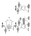
- FIGS. 4A - 4C illustrate the structure of a nozzle of an ink-jet recording head according to the third embodiment.
- FIG. 4A is a plan perspective diagram in which one of a plurality of nozzles of the ink-jet recording head is seen from a direction perpendicular to the main surface of the element substrate 2;
- FIG. 4B is a cross-sectional view taken along line A-A shown in FIG. 4A;
- FIG. 4C is a cross-sectional view taken along line B - B shown in FIG. 4A.
- the opening surface of the second discharge-port portion 10 facing the bubble generation chamber 11 is elliptic or oval in which the diameter in a direction parallel to the direction of arrangement of the first discharge-port portion 4 is larger than the diameter in a direction perpendicular to the direction of arrangement of the first discharge-port portion 4.
- the end surface facing the first discharge-port portion 4 is similar to and has a cross section having a smaller area than the opening surface facing the bubble generation chamber 11.
- the area is reduced by an area of four corners.
- the portion of the four corners is a portion of stagnation where ink does not flow, a fluid resistance equivalent to that in the first or second embodiment can be maintained.
- the third embodiment when continuously discharging ink at a high frequency, since the cross section of the second discharge-port portion 10 parallel to the main surface of the element substrate 2 is smaller by the area of four corners than in the first and second embodiments, the region of stagnation of ink is reduced, and variations in the volume of a discharged droplet are reduced.
- the cross section of the second discharge-port portion 10 parallel to the main surface of the element substrate 2, i.e., the spatial volume, is larger than in the recording head shown in FIGS. 11A - 11C in which the discharge-port portion 4 within the nozzle is cylindrical, a pressure loss is very small, and ink is excellently discharged toward the first discharge-port portion 4. Accordingly, even if the fluid resistance in the direction of the discharge port at the discharge-port portion 4 increases by further reducing the discharge port at the distal end of the nozzle, it is possible to suppress reduction in the flow rate in the direction of the discharge port, and prevent a decrease in the discharge speed of the ink droplet.
- An object of a fourth embodiment of the present invention is also to reduce the region of ink stagnation than in the first embodiment, in order to reduce variations in the discharge volume.
- an object of a fifth embodiment of the present invention is further to remove instable ink discharge due to deviation of a region of stagnation produced at a step portion between the first discharge-port portion 4 and the second discharge-port portion 10, by making the opening surface of the first discharge-port portion 4 facing the second discharge-port portion 10 and the end surface of the second discharge-port portion 10 facing the first discharge-port portion 4 are concentric (in the form of a ring) with respect to the perpendicular drawn from the center of the first discharge-port portion 4 toward the main surface of the element substrate 2.
- FIGS. 5A - 5C illustrate the structure of a nozzle of an ink-jet recording head according to the third embodiment.
- FIG. 5A is a plan perspective diagram in which one of a plurality of nozzles of the ink-jet recording head is seen from a direction perpendicular to the main surface of the element substrate 2;
- FIG. 5B is a cross-sectional view taken along line A-A shown in FIG. 5A;
- FIG. 5C is a cross-sectional view taken along line B - B shown in FIG. 5A.
- the opening surface of the second discharge-port portion 10 facing the bubble generation chamber 11 is elliptic or oval in which the diameter in a direction parallel to the direction of arrangement of the first discharge-port portion 4 is larger than the diameter in a direction perpendicular to the direction of arrangement of the first discharge-port portion 4.
- the end surface of the second discharge-port portion 10 facing the first discharge-port portion 4 is circular, and is inside of the opening surface facing the bubble generation chamber 11.
- the cross section of the second discharge-port portion 10 parallel to the main surface of the element substrate 2 is reduced, there is the possibility that the entire fluid resistance of the second discharge-port portion 10 increases compared with the first embodiment.
- the step portion between the first discharge-port portion 4 and the second discharge-port portion 10 is a portion of stagnation where ink does not flow, a fluid resistance equivalent to that in the first embodiment can be maintained.
- the cross section of the second discharge-port portion 10 parallel to the main surface of the element substrate 2, i.e., the spatial volume, is larger than in the recording head shown in FIGS. 11A - 11C in which the discharge-port portion 4 within the nozzle is cylindrical, a pressure loss is very small, and ink is excellently discharged toward the first discharge-port portion 4. Accordingly, even if the fluid resistance in the direction of the discharge port at the first discharge-port portion 4 increases by further reducing the discharge port at the distal end of the nozzle, it is possible to suppress reduction in the flow rate in the direction of the discharge port, and prevent a decrease in the discharge speed of the ink droplet.
- the cross section of the second discharge-port portion 10 parallel to the main surface of the element substrate 2, i.e., the spatial volume, is larger than in the recording head shown in FIGS. 11A - 11C in which the discharge-port portion 4 within the nozzle is cylindrical, a pressure loss is very small, and ink is excellently discharged toward the first discharge-port portion 4. Accordingly, even if the fluid resistance in the direction of the discharge port at the first discharge-port portion 4 increases by further reducing the discharge port at the distal end of the nozzle, it is possible to suppress reduction in the flow rate in the direction of the discharge port, and prevent a decrease in the discharge speed of the ink droplet.
- the fourth embodiment also, by making the length of the opening surface of the second discharge-port portion 10 facing the bubble generation chamber 11 in a direction perpendicular to the direction of arrangement of the discharge ports longer than the length in a direction parallel to the direction of arrangement of the discharge ports, it is possible to increase the cross section of the second discharge-port portion 10 without being limited by the width of the bubble generation chamber 11 even if the width is reduced in accordance with reduction in the size of the ink droplet. Hence, it is possible to further reduce the entire fluid resistance in the direction of the discharge ports.
- a fifth embodiment of the present invention by providing a sub-supply channel, the total fluid resistance in the two supply channels (the supply channel 9 and a sub-supply channel 12) is reduced to allow refilling processing at a high frequency. Portions in the fifth embodiment that are different from the first embodiment will now be mainly described with reference to FIGS. 6A- 6C.
- FIGS. 6A - 6C illustrate the structure of a nozzle of an ink-jet recording head according to the third embodiment.
- FIG. 6A is a plan perspective diagram in which one of a plurality of nozzles of the ink-jet recording head is seen from a direction perpendicular to the main surface of the element substrate 2;
- FIG. 6B is a cross-sectional view taken along line A-A shown in FIG. 6A;
- FIG. 6C is a cross-sectional view taken along line B - B shown in FIG. 6A.
- the opening surface of the second discharge-port portion 10 facing the bubble generation chamber 11 has a shape such that the length in a direction perpendicular to the direction of arrangement of the first discharge-port portion 4 is larger than the length in a direction parallel to the direction of arrangement of the first discharge-port portion 4.
- the end surface facing the first discharge-port portion 4 is similar to and has a cross section having a smaller area than the opening surface facing the bubble generation chamber 11.
- the cross section obtained by cutting the second discharge-port portion 10 with a plane substantially parallel to the forming surface of the heater 1 is substantially rectangular.
- a sub-ink supply channel 12 is provided in addition to the ink supply channel 9.
- ink supplied into the supply chamber 6 is supplied to the respective nozzles 5 of the first nozzle row 7 and the second nozzle row 8.
- the ink supplied to each of the nozzles 5 is filled into the bubble generation chamber 11 by flowing along the supply channel 9.
- the ink filled within the bubble generation chamber 11 is discharged from the first discharge-port portion 4 as an ink droplet by the pressure of a growing bubble generated by film boiling caused by the heater 1.
- part of the ink within the bubble generation chamber 11 flows toward the supply channel 6 and the sub-supply channel 12 by the pressure of the bubble generated within the bubble generation chamber 11.
- the pressure of the bubble generated within the bubble generation chamber 11 is also transmitted to the second discharge-port portion 10 instantaneously, and ink filled in the bubble generation chamber 11 and the second discharge-port portion 10 moves within the second discharge-port portion 10.
- the cross section of the second discharge-port portion 10 parallel to the main surface of the element substrate 2, i.e., the spatial volume, is larger than in the recording head shown in FIGS. 11A - 11C in which the first discharge-port portion 4 within the nozzle is cylindrical, a pressure loss is very small, and ink is excellently discharged toward the first discharge-port portion 4. Accordingly, even if the fluid resistance in the direction of the discharge port at the first discharge-port portion 4 increases by further reducing the discharge port at the distal end of the nozzle, it is possible to suppress reduction in the flow rate in the direction of the discharge port, and prevent a decrease in the discharge speed of the ink droplet.
- the fifth embodiment in order to deal with reduction in the amount a discharged ink droplet (provision of a small ink droplet), by providing two supply channels, the total fluid resistance at the two supply channels is reduced, thereby allowing refilling at a high frequency.
- the opening surface of the second discharge-port portion 10 facing the bubble generation chamber 11 is increased by making the length in a direction perpendicular to the direction of arrangement of the discharge ports larger than the length in a direction parallel to the direction of arrangement of the discharge ports, and the lengths of the two supply channels (i.e., the supply channel 9 and the sub-supply channel 12) having a fluid resistance larger than in the second discharge-port portion 10 in a direction perpendicular to the direction of arrangement of the nozzles (i.e., the direction of ink supply) are shortened.
- the two supply channels i.e., the supply channel 9 and the sub-supply channel 12
- the discharge efficiency is improved by providing a second discharge-port portion having a small fluid resistance.
- the energy of the heater i.e., the area of the heater, may be increased.
- the nozzle arrangement density must be increased.
- a heater (a longitudinal heater) is provided in which the length in a direction perpendicular to the direction of arrangement of discharge ports is larger than the length in a direction parallel to the direction of arrangement of the discharge ports.
- the heater In order to realize energy saving, it is necessary to output discharge energy equivalent to the current energy value with a small current. For that purpose, the heater must have a high electric resistance.
- the longitudinal heater is suitable for this purpose because this heater is long in the direction of wiring (not shown).
- the bubble pressure has a spread in a direction perpendicular to the direction of arrangement of the discharge ports.
- the opening surface of the second discharge-port portion facing the bubble generation chamber is large in a direction perpendicular to the direction of arrangement of the discharge ports, even the bubble pressure having the spread can be sufficiently utilized as energy in a direction of ink discharge.
- FIGS. 7A - 7C illustrate the structure of a nozzle of an ink-jet recording head according to the sixth embodiment.
- FIG. 7A is a plan perspective diagram in which one of a plurality of nozzles of the ink-jet recording head is seen from a direction perpendicular to the main surface of the element substrate 2;
- FIG. 7B is a cross-sectional view taken along line A - A shown in FIG. 7A; and
- FIG. 7C is a cross-sectional view taken along line B - B shown in FIG. 7A.
- the cross section of the second discharge-port portion 10 that is parallel to the main surface of the element substrate 2 has a shape such that the length in a direction perpendicular to the direction of arrangement of the first discharge-port portion 4 is larger than the length in a direction parallel to the direction of arrangement of the first discharge-port portion 4 at any cross section from the opening surface facing the bubble generation chamber 11 to the end surface facing the first discharge-port portion 4.
- the opening surface facing the first discharge-port portion 4 is similar to and has a cross section having a smaller area than the opening surface facing the bubble generation chamber 11.
- the cross section obtained by cutting the second discharge-port portion 10 with a plane substantially parallel to the forming surface of the heater 1 is substantially rectangular.
- the heater 1 has a rectangular shape such that the length in a direction perpendicular to the direction of arrangement of the discharge ports is longer than the length in a direction parallel to the direction of arrangement of the discharge ports.
- a heater is provided in which the length in a direction perpendicular to the direction of arrangement of discharge ports is larger than the length in a direction parallel to the direction of arrangement of the discharge ports, is provided.
- the bubble pressure due to thermal energy generated by the heater has a spread in a direction perpendicular to the direction of arrangement of the discharge ports.
- the opening surface of the second discharge-port portion facing the bubble generation chamber is large in a direction perpendicular to the direction of arrangement of the discharge ports, even the bubble pressure having the spread can be sufficiently utilized as energy in a direction of ink discharge.
- the opening surface of the second discharge-port portion facing the bubble generation chamber is provided at a position facing the heater, with a rectangular shape that is substantially the same as the shape of the heater.
- the opening surface of the second discharge-port portion facing the first discharge port portion may have a shape identical to the shape of the effective bubble generation region that contributes to bubble generation. Even if the heater is more or less larger than the opening surface of the second discharge-port portion facing the first discharge-port portion by taking into consideration of the effective bubble generation region, the opening surface of the second discharge-port portion facing the bubble generation chamber is assumed to have a shape substantially identical to the shape of the heater.
- the sixth embodiment also, by making the length of the opening surface of the second discharge-port portion 10 facing the bubble generation chamber in a direction perpendicular to the direction of arrangement of the discharge ports longer than the length in a direction parallel to the direction of arrangement of the discharge ports, it is possible to increase the cross section of the second discharge-port portion 10 without being limited by the width of the bubble generation chamber 11 even if the width is reduced in order to provide a small ink droplet. Hence, it is possible to further reduce the entire fluid resistance in the direction of the discharge ports.
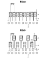
- FIGS. 8 and 9 illustrates the arrangement of a plurality of nozzles of the above-described ink-jet recording head.
- a plurality of discharge ports are arranged along the supply chamber 6 with a pitch of 1,200 dpi.
- each of the nozzles of the above-described embodiments it is preferable to provide a configuration in which the cross section of each of the first discharge-port portion 4 and the second discharge-port portion 10 at the end surface of the second discharge-port portion 10 facing the first discharge-port portion 4 has a shape such that the ratio of the length of the second discharge-port portion 10 to the length of the first discharge-port portion 4 in a direction perpendicular to the direction of arrangement of the discharge ports is larger than the ratio of the length of the second discharge-port portion 10 to the length of the first discharge-port portion 4 in a direction parallel to the direction of arrangement of the discharge ports.
- Each of the above-described embodiments may also be applied to an ink-jet recording head for discharging a plurality of ink droplets having different volumes.
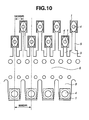
- FIG. 10 it is preferable to adopt the configuration of each of the above-described embodiments to a nozzle for discharging an ink droplet having a relatively small volume.
- the configuration of each of the above-described embodiments may also be applied to a nozzle for discharging an ink droplet having a relatively large volume.
Landscapes
- Physics & Mathematics (AREA)
- Geometry (AREA)
- Particle Formation And Scattering Control In Inkjet Printers (AREA)
Abstract
Description
Claims (13)
- An ink-jet recording head comprising:wherein each of said discharge-port portions comprises a first discharge-port portion continuing from one of said discharge ports, and a second discharge-port portion for causing said first discharge-port portion to communicate with one of said bubble generation chambers,a channel-configuration substrate comprising:a plurality of discharge ports for discharging a liquid;a plurality of bubble generation chambers for generating bubbles utilized for discharging the liquid by thermal energy generated by electrothermal transducers;a plurality of discharge-port portions for causing said discharge ports to communicate with said bubble generation chambers; andat least one supply channel for supplying said discharge-port portions and said bubble generation chambers with ink; andan element substrate on which said electrothermal transducers are provided, and to a main surface of which said channel-configuration substrate is connected,
wherein said second discharge-port portion has an end surface that includes a border portion with said first discharge-port portion and is parallel to the main surface of said element substrate, and an area of a cross section of said second discharge-port portion that is parallel to the main surface of said element substrate is larger than an area of the border portion at any cross section of said second discharge-port portion from an opening surface facing said bubble generation chamber to the end surface facing said first discharge-port portion, and
wherein a cross section of the opening surface of said second discharge-port portion facing said bubble generation chamber that is parallel to the main surface of said element substrate has a shape such that a length in a direction perpendicular to a direction of arrangement of said discharge ports is larger than a length in a direction parallel to the direction of arrangement of said discharge ports. - An ink-jet recording head according to Claim 1, wherein a cross section of said second discharge-port portion at the end portion facing said first discharge-port portion has a shape such that a ratio of a length of said second discharge-port portion to a length of said first discharge-port portion in a direction perpendicular to the direction of arrangement of said discharge ports is larger than a ratio of a length of said second discharge-port portion to a length of said first discharge-port portion in a direction parallel to the direction of arrangement of said discharge ports.
- An ink-jet recording head according to Claim 1, wherein the opening surface of said second discharge-port portion facing said bubble generation chamber is elliptic or oval.
- An ink-jet recording apparatus according to Claim 1, wherein the opening surface of said second discharge-port portion facing said bubble generation chamber and the end portion of said second discharge-port portion facing said first discharge-port portion have similar shapes.
- An ink-jet recording head according to Claim 1, wherein the opening surface of said second discharge-port portion facing said bubble generation chamber and the end portion of said second discharge-port portion facing said first discharge-port portion have an identical shape.
- An ink-jet recording head according to Claim 1, wherein the end surface of said second discharge-port portion facing said first discharge-port portion is smaller than the opening surface of said second discharge-port portion facing said bubble generation chamber.
- An ink-jet recording head according to Claim 1, wherein a length of said electrothermal transducer in a direction perpendicular to the direction of arrangement of said discharge ports is larger than a length of said electrothermal transducer in a direction parallel to the direction of arrangement of said discharge ports.
- An ink-jet recording head according to Claim 1 wherein a length of said second discharge-port portion facing said bubble generation chamber in the direction of arrangement of said discharge ports is substantially equivalent to a length of said electrothermal transducer in the direction of arrangement of said discharge ports.
- An ink-jet recording head according to Claim 1, wherein a channel wall is provided at a portion opposite to said supply channel across said electrothermal transducer.
- An ink-jet recording head according to Claim 1, wherein said supply channel is provided in two directions facing with respect to said electrothermal transducer.
- An ink-jet recording head according to Claim 1, wherein on said channel-configuration substrate, a first discharge-port row in which a longitudinal direction of each of said discharge ports is arranged in parallel, and a second discharge-port row in which a longitudinal direction of each of said discharge ports is arranged in parallel at a position facing said first discharge-port row, each of said first discharge-port row and said second discharge-port row comprising a plurality of said electrothermal transducers and a plurality of said discharge-port portions, are provided, and wherein said discharge ports of said second discharge-port portion are arranged in a state of being shifted by 1/2 of a pitch between adjacent ones of said discharge ports, with respect to said discharge ports of said first discharge-port portion.
- An ink-jet recording head according to Claim 1, wherein a bubble generated by said electrothermal transducer communicates with external air.
- An ink-jet recording head comprising:wherein each of said discharge-port portions comprises a first discharge-port portion continuing from one of said discharge ports, and a second discharge-port portion for causing said first discharge-port portion to communicate with one of said pressure chambers,a channel-configuration substrate comprising:a plurality of discharge ports for discharging a liquid;a plurality of pressure chambers for generating pressures utilized for discharging the liquid by discharge-energy generation elements;a plurality of discharge-port portions for causing said discharge ports to communicate with said pressure chambers; andat least one supply channel for supplying said discharge-port portion and said pressure chamber with ink; andan element substrate on which said discharge-energy generation elements are provided, and to a main surface of which said channel-configuration substrate is connected,
wherein said second discharge-port portion has an end surface that includes a border portion with said first discharge-port portion and is parallel to the main surface of said element substrate, and an area of a cross section of said second discharge-port portion that is parallel to the main surface of said element substrate is larger than an area of the border portion at any cross section of said second discharge-port portion from an opening surface facing said pressure chamber to the end surface facing said first discharge-port portion,
wherein a cross section of the opening surface of said second discharge-port portion facing said pressure chamber that is parallel to the main surface of said element substrate has a shape such that a length in a direction perpendicular to a direction of arrangement of said discharge ports is larger than a length in a direction parallel to the direction of arrangement of said discharge ports, and
wherein a cross section of said second discharge-port portion at the end surface facing said first discharge-port portion has a shape such that a ratio of a length of said second discharge-port portion to a length of said first discharge-port portion in the direction perpendicular to the direction of arrangement of said discharge ports is larger than a ratio of a length of said second discharge-port portion to a length of said first discharge-port portion in the direction parallel to the direction of arrangement of said discharge ports.
Applications Claiming Priority (4)
| Application Number | Priority Date | Filing Date | Title |
|---|---|---|---|
| JP2003004306 | 2003-01-10 | ||
| JP2003004306 | 2003-01-10 | ||
| JP2003427054A JP4323947B2 (en) | 2003-01-10 | 2003-12-24 | Inkjet recording head |
| JP2003427054 | 2003-12-24 |
Publications (3)
| Publication Number | Publication Date |
|---|---|
| EP1437223A2 true EP1437223A2 (en) | 2004-07-14 |
| EP1437223A3 EP1437223A3 (en) | 2005-06-01 |
| EP1437223B1 EP1437223B1 (en) | 2009-10-07 |
Family
ID=32510693
Family Applications (1)
| Application Number | Title | Priority Date | Filing Date |
|---|---|---|---|
| EP03029989A Expired - Lifetime EP1437223B1 (en) | 2003-01-10 | 2003-12-31 | Ink-jet recording head |
Country Status (5)
| Country | Link |
|---|---|
| US (2) | US7628472B2 (en) |
| EP (1) | EP1437223B1 (en) |
| JP (1) | JP4323947B2 (en) |
| KR (1) | KR100554041B1 (en) |
| DE (1) | DE60329571D1 (en) |
Cited By (1)
| Publication number | Priority date | Publication date | Assignee | Title |
|---|---|---|---|---|
| EP2230081A1 (en) * | 2009-03-18 | 2010-09-22 | Toshiba TEC Kabushiki Kaisha | Ink jet head and printing method using the same |
Families Citing this family (24)
| Publication number | Priority date | Publication date | Assignee | Title |
|---|---|---|---|---|
| JP4323947B2 (en) * | 2003-01-10 | 2009-09-02 | キヤノン株式会社 | Inkjet recording head |
| JP4311050B2 (en) * | 2003-03-18 | 2009-08-12 | セイコーエプソン株式会社 | Functional droplet ejection head drive control method and functional droplet ejection apparatus |
| WO2006051762A1 (en) * | 2004-11-10 | 2006-05-18 | Canon Kabushiki Kaisha | Liquid discharge head |
| JP4574515B2 (en) * | 2004-11-10 | 2010-11-04 | キヤノン株式会社 | Liquid discharge head |
| JP4553360B2 (en) * | 2004-12-24 | 2010-09-29 | キヤノン株式会社 | Inkjet recording head |
| JP4614388B2 (en) * | 2005-04-01 | 2011-01-19 | キヤノン株式会社 | Recording apparatus, recording head, and driving method thereof |
| JP2007223146A (en) * | 2006-02-23 | 2007-09-06 | Fujifilm Corp | Liquid discharge head and image forming apparatus provided with the same |
| JP4856982B2 (en) * | 2006-03-02 | 2012-01-18 | キヤノン株式会社 | Inkjet recording head |
| JP4994924B2 (en) * | 2006-05-02 | 2012-08-08 | キヤノン株式会社 | Inkjet recording head |
| US7909434B2 (en) * | 2006-10-27 | 2011-03-22 | Hewlett-Packard Development Company, L.P. | Printhead and method of printing |
| JP5037903B2 (en) | 2006-11-09 | 2012-10-03 | キヤノン株式会社 | Inkjet recording head and inkjet recording apparatus |
| JP5058719B2 (en) * | 2007-08-30 | 2012-10-24 | キヤノン株式会社 | Liquid discharge head and ink jet recording apparatus |
| JP5264123B2 (en) * | 2007-08-31 | 2013-08-14 | キヤノン株式会社 | Liquid discharge head |
| US7735962B2 (en) * | 2007-08-31 | 2010-06-15 | Canon Kabushiki Kaisha | Ink jet print head |
| JP5031534B2 (en) * | 2007-11-30 | 2012-09-19 | キヤノン株式会社 | Inkjet recording head |
| JP5590813B2 (en) * | 2008-04-30 | 2014-09-17 | キヤノン株式会社 | Inkjet recording method, recording unit, and inkjet recording apparatus |
| JP5393082B2 (en) * | 2008-08-29 | 2014-01-22 | キヤノン株式会社 | Liquid discharge head |
| JP2012152970A (en) * | 2011-01-25 | 2012-08-16 | Seiko Epson Corp | Liquid ejecting head and liquid ejecting apparatus |
| US20120274707A1 (en) * | 2011-04-29 | 2012-11-01 | Xiaorong Cai | Ejection devices for inkjet printers and method for fabricating ejection devices |
| US10293607B2 (en) * | 2016-01-08 | 2019-05-21 | Canon Kabushiki Kaisha | Recording element board and liquid discharge head |
| JP6381581B2 (en) * | 2016-05-30 | 2018-08-29 | キヤノン株式会社 | Recording element substrate and liquid discharge head |
| US10300698B2 (en) | 2017-06-05 | 2019-05-28 | Canon Kabushiki Kaisha | Liquid ejection head |
| JP7286403B2 (en) * | 2019-04-26 | 2023-06-05 | キヤノン株式会社 | LIQUID EJECTION HEAD, LIQUID EJECTION DEVICE, AND RECORDING DEVICE |
| JP2024029581A (en) * | 2022-08-22 | 2024-03-06 | キヤノン株式会社 | Liquid ejection head and liquid ejection device |
Family Cites Families (39)
| Publication number | Priority date | Publication date | Assignee | Title |
|---|---|---|---|---|
| JPS54161935A (en) | 1978-06-12 | 1979-12-22 | Seiko Epson Corp | Ink jet printer |
| JPS61185455A (en) | 1985-02-14 | 1986-08-19 | Olympus Optical Co Ltd | Ink jet printer |
| JPS61249768A (en) | 1985-04-30 | 1986-11-06 | Olympus Optical Co Ltd | Ink jet recording apparatus |
| DE3604844A1 (en) | 1986-02-15 | 1987-08-20 | Daimler Benz Ag | VIBRATION DAMPER FOR VEHICLES |
| JPS62194045U (en) * | 1986-06-02 | 1987-12-10 | ||
| JPH0735139B2 (en) | 1987-09-14 | 1995-04-19 | 株式会社ケンウッド | Lighting equipment for in-vehicle equipment |
| JPH0174142U (en) * | 1987-11-07 | 1989-05-19 | ||
| JPH0410941A (en) | 1990-04-27 | 1992-01-16 | Canon Inc | Droplet jetting method and recording device using the method |
| JP2783647B2 (en) | 1990-04-27 | 1998-08-06 | キヤノン株式会社 | Liquid ejection method and recording apparatus using the method |
| JPH0412859A (en) * | 1990-04-28 | 1992-01-17 | Canon Inc | Liquid ejection method, recording head using the method, and recording device using the method |
| JPH04232752A (en) | 1990-06-24 | 1992-08-21 | Lexmark Internatl Inc | Ink jet print head and ink jet printing method |
| US5455613A (en) * | 1990-10-31 | 1995-10-03 | Hewlett-Packard Company | Thin film resistor printhead architecture for thermal ink jet pens |
| JPH05177834A (en) * | 1991-06-04 | 1993-07-20 | Seiko Epson Corp | Inkjet recording head |
| JP3044863B2 (en) * | 1991-09-27 | 2000-05-22 | セイコーエプソン株式会社 | Inkjet head |
| JP3165717B2 (en) * | 1991-10-29 | 2001-05-14 | キヤノン株式会社 | Ink jet recording head and recording method using the same |
| DE69333236T2 (en) * | 1992-06-29 | 2004-08-05 | Hewlett-Packard Co. (N.D.Ges.D.Staates Delaware), Palo Alto | Thin film resistance printhead for thermal inkjet printers |
| JP3189484B2 (en) * | 1993-04-19 | 2001-07-16 | セイコーエプソン株式会社 | Inkjet head |
| US5825385A (en) * | 1995-04-12 | 1998-10-20 | Eastman Kodak Company | Constructions and manufacturing processes for thermally activated print heads |
| WO1996032267A1 (en) * | 1995-04-12 | 1996-10-17 | Eastman Kodak Company | Constructions and manufacturing processes for thermally activated print heads |
| JPH0952358A (en) * | 1995-08-14 | 1997-02-25 | Fujitsu Ltd | Inkjet printer |
| US6527369B1 (en) * | 1995-10-25 | 2003-03-04 | Hewlett-Packard Company | Asymmetric printhead orifice |
| US6557974B1 (en) * | 1995-10-25 | 2003-05-06 | Hewlett-Packard Company | Non-circular printhead orifice |
| US6113221A (en) * | 1996-02-07 | 2000-09-05 | Hewlett-Packard Company | Method and apparatus for ink chamber evacuation |
| JP3183206B2 (en) | 1996-04-08 | 2001-07-09 | 富士ゼロックス株式会社 | Ink jet print head, method of manufacturing the same, and ink jet recording apparatus |
| US6158843A (en) | 1997-03-28 | 2000-12-12 | Lexmark International, Inc. | Ink jet printer nozzle plates with ink filtering projections |
| JP3675272B2 (en) * | 1999-01-29 | 2005-07-27 | キヤノン株式会社 | Liquid discharge head and method for manufacturing the same |
| JP2000334965A (en) * | 1999-05-28 | 2000-12-05 | Ricoh Co Ltd | Nozzle forming member, inkjet head, and method of manufacturing nozzle forming member |
| JP2001277499A (en) * | 2000-03-30 | 2001-10-09 | Kyocera Corp | Inkjet recording head |
| JP2002036569A (en) * | 2000-07-27 | 2002-02-05 | Ricoh Co Ltd | Ink jet head and image forming apparatus |
| US6902252B1 (en) | 2000-08-16 | 2005-06-07 | Hewlett-Packard Development Company, L.P. | Fluid ejection device with staggered ink drop generators |
| KR100406941B1 (en) * | 2000-09-30 | 2003-11-21 | 삼성전자주식회사 | Ink jet printer head |
| JP3871320B2 (en) * | 2001-06-21 | 2007-01-24 | キヤノン株式会社 | Inkjet recording head |
| JP2003025577A (en) * | 2001-07-11 | 2003-01-29 | Canon Inc | Liquid discharge head |
| US6854820B2 (en) * | 2001-09-26 | 2005-02-15 | Canon Kabushiki Kaisha | Method for ejecting liquid, liquid ejection head and image-forming apparatus using the same |
| US6942318B2 (en) * | 2002-05-31 | 2005-09-13 | Hewlett-Packard Development Company, L.P. | Chamber having a protective layer |
| JP4027282B2 (en) | 2002-07-10 | 2007-12-26 | キヤノン株式会社 | Inkjet recording head |
| JP4027281B2 (en) | 2002-07-10 | 2007-12-26 | キヤノン株式会社 | Inkjet recording head |
| JP4323947B2 (en) * | 2003-01-10 | 2009-09-02 | キヤノン株式会社 | Inkjet recording head |
| JP4232752B2 (en) | 2005-03-28 | 2009-03-04 | パナソニック株式会社 | Electronic component mounting apparatus and electronic component mounting method |
-
2003
- 2003-12-24 JP JP2003427054A patent/JP4323947B2/en not_active Expired - Fee Related
- 2003-12-30 US US10/747,204 patent/US7628472B2/en not_active Expired - Fee Related
- 2003-12-31 EP EP03029989A patent/EP1437223B1/en not_active Expired - Lifetime
- 2003-12-31 DE DE60329571T patent/DE60329571D1/en not_active Expired - Lifetime
-
2004
- 2004-01-09 KR KR1020040001431A patent/KR100554041B1/en not_active Expired - Fee Related
-
2009
- 2009-10-27 US US12/606,372 patent/US8083322B2/en not_active Expired - Fee Related
Cited By (2)
| Publication number | Priority date | Publication date | Assignee | Title |
|---|---|---|---|---|
| EP2230081A1 (en) * | 2009-03-18 | 2010-09-22 | Toshiba TEC Kabushiki Kaisha | Ink jet head and printing method using the same |
| US8733898B2 (en) | 2009-03-18 | 2014-05-27 | Toshiba Tec Kabushiki Kaisha | Ink jet head, nozzle plate thereof and printing method using the same |
Also Published As
| Publication number | Publication date |
|---|---|
| US20040218007A1 (en) | 2004-11-04 |
| EP1437223A3 (en) | 2005-06-01 |
| US8083322B2 (en) | 2011-12-27 |
| JP2004230885A (en) | 2004-08-19 |
| JP4323947B2 (en) | 2009-09-02 |
| EP1437223B1 (en) | 2009-10-07 |
| KR20040064637A (en) | 2004-07-19 |
| KR100554041B1 (en) | 2006-02-24 |
| US20100045748A1 (en) | 2010-02-25 |
| US7628472B2 (en) | 2009-12-08 |
| DE60329571D1 (en) | 2009-11-19 |
Similar Documents
| Publication | Publication Date | Title |
|---|---|---|
| US8083322B2 (en) | Ink-jet recording head | |
| KR100977645B1 (en) | Liquid discharge head | |
| RU2394688C1 (en) | Jet printing head | |
| CN101797841B (en) | inkjet print head | |
| EP3970977B1 (en) | Element substrate and liquid ejection head | |
| JP4027282B2 (en) | Inkjet recording head | |
| US20060077233A1 (en) | Ink jet recording head and ink discharge method | |
| US8083325B2 (en) | Liquid ejection recording head having element substrate with plural supply ports | |
| JP4027281B2 (en) | Inkjet recording head | |
| JP5230084B2 (en) | Inkjet recording head | |
| JP5031534B2 (en) | Inkjet recording head | |
| JP4574385B2 (en) | Ink jet recording head and recording apparatus | |
| JP4208399B2 (en) | Inkjet recording apparatus and inkjet recording method | |
| JP4137164B2 (en) | Inkjet recording head | |
| US7441878B2 (en) | Ink jet recording head including temperature adjustment heater | |
| JPH05104720A (en) | Ink jet record head and recording device | |
| JP3586987B2 (en) | Inkjet print head | |
| JP2005125696A (en) | Inkjet recording head | |
| JP6312547B2 (en) | Inkjet head and printer | |
| JP2007301937A (en) | RECORDING HEAD AND RECORDING HEAD SUBSTRATE | |
| JPH1110881A (en) | Recording head and recording device | |
| JPH04211950A (en) | Liquid jet recording head and apparatus | |
| JPH06316075A (en) | Thermal ink jet and print head | |
| JP2008149611A (en) | Inkjet recording method | |
| JP2013240900A (en) | Liquid discharge recording head |
Legal Events
| Date | Code | Title | Description |
|---|---|---|---|
| PUAI | Public reference made under article 153(3) epc to a published international application that has entered the european phase |
Free format text: ORIGINAL CODE: 0009012 |
|
| AK | Designated contracting states |
Kind code of ref document: A2 Designated state(s): AT BE BG CH CY CZ DE DK EE ES FI FR GB GR HU IE IT LI LU MC NL PT RO SE SI SK TR |
|
| AX | Request for extension of the european patent |
Extension state: AL LT LV MK |
|
| PUAL | Search report despatched |
Free format text: ORIGINAL CODE: 0009013 |
|
| AK | Designated contracting states |
Kind code of ref document: A3 Designated state(s): AT BE BG CH CY CZ DE DK EE ES FI FR GB GR HU IE IT LI LU MC NL PT RO SE SI SK TR |
|
| AX | Request for extension of the european patent |
Extension state: AL LT LV MK |
|
| RIC1 | Information provided on ipc code assigned before grant |
Ipc: 7B 41J 2/14 A Ipc: 7B 41J 2/145 B |
|
| 17P | Request for examination filed |
Effective date: 20051201 |
|
| AKX | Designation fees paid |
Designated state(s): DE FR GB IT |
|
| 17Q | First examination report despatched |
Effective date: 20070115 |
|
| GRAP | Despatch of communication of intention to grant a patent |
Free format text: ORIGINAL CODE: EPIDOSNIGR1 |
|
| GRAS | Grant fee paid |
Free format text: ORIGINAL CODE: EPIDOSNIGR3 |
|
| GRAA | (expected) grant |
Free format text: ORIGINAL CODE: 0009210 |
|
| AK | Designated contracting states |
Kind code of ref document: B1 Designated state(s): DE FR GB IT |
|
| REG | Reference to a national code |
Ref country code: GB Ref legal event code: FG4D |
|
| REF | Corresponds to: |
Ref document number: 60329571 Country of ref document: DE Date of ref document: 20091119 Kind code of ref document: P |
|
| PLBE | No opposition filed within time limit |
Free format text: ORIGINAL CODE: 0009261 |
|
| STAA | Information on the status of an ep patent application or granted ep patent |
Free format text: STATUS: NO OPPOSITION FILED WITHIN TIME LIMIT |
|
| 26N | No opposition filed |
Effective date: 20100708 |
|
| REG | Reference to a national code |
Ref country code: FR Ref legal event code: PLFP Year of fee payment: 13 |
|
| REG | Reference to a national code |
Ref country code: FR Ref legal event code: PLFP Year of fee payment: 14 |
|
| PGFP | Annual fee paid to national office [announced via postgrant information from national office to epo] |
Ref country code: GB Payment date: 20161230 Year of fee payment: 14 |
|
| PGFP | Annual fee paid to national office [announced via postgrant information from national office to epo] |
Ref country code: IT Payment date: 20161207 Year of fee payment: 14 Ref country code: FR Payment date: 20161223 Year of fee payment: 14 |
|
| PGFP | Annual fee paid to national office [announced via postgrant information from national office to epo] |
Ref country code: DE Payment date: 20161231 Year of fee payment: 14 |
|
| REG | Reference to a national code |
Ref country code: DE Ref legal event code: R119 Ref document number: 60329571 Country of ref document: DE |
|
| GBPC | Gb: european patent ceased through non-payment of renewal fee |
Effective date: 20171231 |
|
| REG | Reference to a national code |
Ref country code: FR Ref legal event code: ST Effective date: 20180831 |
|
| PG25 | Lapsed in a contracting state [announced via postgrant information from national office to epo] |
Ref country code: FR Free format text: LAPSE BECAUSE OF NON-PAYMENT OF DUE FEES Effective date: 20180102 Ref country code: IT Free format text: LAPSE BECAUSE OF NON-PAYMENT OF DUE FEES Effective date: 20171231 Ref country code: DE Free format text: LAPSE BECAUSE OF NON-PAYMENT OF DUE FEES Effective date: 20180703 |
|
| PG25 | Lapsed in a contracting state [announced via postgrant information from national office to epo] |
Ref country code: GB Free format text: LAPSE BECAUSE OF NON-PAYMENT OF DUE FEES Effective date: 20171231 |