EP1437254A1 - Régulateur de vitesse avec régulation de la distance entre deux véhicules - Google Patents
Régulateur de vitesse avec régulation de la distance entre deux véhicules Download PDFInfo
- Publication number
- EP1437254A1 EP1437254A1 EP20030100024 EP03100024A EP1437254A1 EP 1437254 A1 EP1437254 A1 EP 1437254A1 EP 20030100024 EP20030100024 EP 20030100024 EP 03100024 A EP03100024 A EP 03100024A EP 1437254 A1 EP1437254 A1 EP 1437254A1
- Authority
- EP
- European Patent Office
- Prior art keywords
- target
- host vehicle
- vehicle
- velocity
- controller
- Prior art date
- Legal status (The legal status is an assumption and is not a legal conclusion. Google has not performed a legal analysis and makes no representation as to the accuracy of the status listed.)
- Granted
Links
- 230000003044 adaptive effect Effects 0.000 title claims abstract description 13
- 230000004044 response Effects 0.000 claims abstract description 13
- 238000000034 method Methods 0.000 claims description 17
- 230000003213 activating effect Effects 0.000 claims description 6
- 230000009471 action Effects 0.000 description 8
- 230000001133 acceleration Effects 0.000 description 3
- 238000001514 detection method Methods 0.000 description 3
- 238000010586 diagram Methods 0.000 description 3
- 238000013459 approach Methods 0.000 description 2
- 230000005540 biological transmission Effects 0.000 description 2
- 230000008859 change Effects 0.000 description 2
- 238000003825 pressing Methods 0.000 description 2
- 230000011664 signaling Effects 0.000 description 2
- 230000007704 transition Effects 0.000 description 2
- 238000010276 construction Methods 0.000 description 1
- 230000000881 depressing effect Effects 0.000 description 1
- 230000007613 environmental effect Effects 0.000 description 1
- 239000000446 fuel Substances 0.000 description 1
- 230000006870 function Effects 0.000 description 1
- 230000007257 malfunction Effects 0.000 description 1
- 238000004519 manufacturing process Methods 0.000 description 1
- 230000007246 mechanism Effects 0.000 description 1
- 230000007420 reactivation Effects 0.000 description 1
- 238000012552 review Methods 0.000 description 1
- 230000000007 visual effect Effects 0.000 description 1
Images
Classifications
-
- B—PERFORMING OPERATIONS; TRANSPORTING
- B60—VEHICLES IN GENERAL
- B60W—CONJOINT CONTROL OF VEHICLE SUB-UNITS OF DIFFERENT TYPE OR DIFFERENT FUNCTION; CONTROL SYSTEMS SPECIALLY ADAPTED FOR HYBRID VEHICLES; ROAD VEHICLE DRIVE CONTROL SYSTEMS FOR PURPOSES NOT RELATED TO THE CONTROL OF A PARTICULAR SUB-UNIT
- B60W30/00—Purposes of road vehicle drive control systems not related to the control of a particular sub-unit, e.g. of systems using conjoint control of vehicle sub-units
- B60W30/14—Adaptive cruise control
- B60W30/16—Control of distance between vehicles, e.g. keeping a distance to preceding vehicle
- B60W30/17—Control of distance between vehicles, e.g. keeping a distance to preceding vehicle with provision for special action when the preceding vehicle comes to a halt, e.g. stop and go
-
- B—PERFORMING OPERATIONS; TRANSPORTING
- B60—VEHICLES IN GENERAL
- B60W—CONJOINT CONTROL OF VEHICLE SUB-UNITS OF DIFFERENT TYPE OR DIFFERENT FUNCTION; CONTROL SYSTEMS SPECIALLY ADAPTED FOR HYBRID VEHICLES; ROAD VEHICLE DRIVE CONTROL SYSTEMS FOR PURPOSES NOT RELATED TO THE CONTROL OF A PARTICULAR SUB-UNIT
- B60W30/00—Purposes of road vehicle drive control systems not related to the control of a particular sub-unit, e.g. of systems using conjoint control of vehicle sub-units
- B60W30/14—Adaptive cruise control
- B60W30/16—Control of distance between vehicles, e.g. keeping a distance to preceding vehicle
-
- B—PERFORMING OPERATIONS; TRANSPORTING
- B60—VEHICLES IN GENERAL
- B60K—ARRANGEMENT OR MOUNTING OF PROPULSION UNITS OR OF TRANSMISSIONS IN VEHICLES; ARRANGEMENT OR MOUNTING OF PLURAL DIVERSE PRIME-MOVERS IN VEHICLES; AUXILIARY DRIVES FOR VEHICLES; INSTRUMENTATION OR DASHBOARDS FOR VEHICLES; ARRANGEMENTS IN CONNECTION WITH COOLING, AIR INTAKE, GAS EXHAUST OR FUEL SUPPLY OF PROPULSION UNITS IN VEHICLES
- B60K31/00—Vehicle fittings, acting on a single sub-unit only, for automatically controlling vehicle speed, i.e. preventing speed from exceeding an arbitrarily established velocity or maintaining speed at a particular velocity, as selected by the vehicle operator
- B60K31/0008—Vehicle fittings, acting on a single sub-unit only, for automatically controlling vehicle speed, i.e. preventing speed from exceeding an arbitrarily established velocity or maintaining speed at a particular velocity, as selected by the vehicle operator including means for detecting potential obstacles in vehicle path
-
- B—PERFORMING OPERATIONS; TRANSPORTING
- B60—VEHICLES IN GENERAL
- B60T—VEHICLE BRAKE CONTROL SYSTEMS OR PARTS THEREOF; BRAKE CONTROL SYSTEMS OR PARTS THEREOF, IN GENERAL; ARRANGEMENT OF BRAKING ELEMENTS ON VEHICLES IN GENERAL; PORTABLE DEVICES FOR PREVENTING UNWANTED MOVEMENT OF VEHICLES; VEHICLE MODIFICATIONS TO FACILITATE COOLING OF BRAKES
- B60T7/00—Brake-action initiating means
- B60T7/12—Brake-action initiating means for automatic initiation; for initiation not subject to will of driver or passenger
- B60T7/22—Brake-action initiating means for automatic initiation; for initiation not subject to will of driver or passenger initiated by contact of vehicle, e.g. bumper, with an external object, e.g. another vehicle, or by means of contactless obstacle detectors mounted on the vehicle
-
- B—PERFORMING OPERATIONS; TRANSPORTING
- B60—VEHICLES IN GENERAL
- B60T—VEHICLE BRAKE CONTROL SYSTEMS OR PARTS THEREOF; BRAKE CONTROL SYSTEMS OR PARTS THEREOF, IN GENERAL; ARRANGEMENT OF BRAKING ELEMENTS ON VEHICLES IN GENERAL; PORTABLE DEVICES FOR PREVENTING UNWANTED MOVEMENT OF VEHICLES; VEHICLE MODIFICATIONS TO FACILITATE COOLING OF BRAKES
- B60T2201/00—Particular use of vehicle brake systems; Special systems using also the brakes; Special software modules within the brake system controller
- B60T2201/02—Active or adaptive cruise control system; Distance control
-
- B—PERFORMING OPERATIONS; TRANSPORTING
- B60—VEHICLES IN GENERAL
- B60W—CONJOINT CONTROL OF VEHICLE SUB-UNITS OF DIFFERENT TYPE OR DIFFERENT FUNCTION; CONTROL SYSTEMS SPECIALLY ADAPTED FOR HYBRID VEHICLES; ROAD VEHICLE DRIVE CONTROL SYSTEMS FOR PURPOSES NOT RELATED TO THE CONTROL OF A PARTICULAR SUB-UNIT
- B60W2520/00—Input parameters relating to overall vehicle dynamics
- B60W2520/10—Longitudinal speed
Definitions
- the present invention relates generally to vehicle adaptive cruise control systems and more particularly to a method and apparatus for adjusting vehicle speed and maintaining a headway distance in response to a target.
- Adaptive Cruise Control has reached a level of technical and business readiness such that it is beginning to appear in the consumer market as a comfort and convenience system. Consumer technical enthusiasm for ACC has increased because of their interest in intelligent vehicles and systems such as collision warning and collision avoidance. ACC performs as an enhancement to traditional cruise control by automatically adjusting a set speed, which is set by the vehicle operator, to allow a vehicle to adapt to moving traffic.
- the ACC system Under normal driving conditions the ACC system is engaged with a set speed equal to a maximum autonomous speed that is desired by the operator and the ACC system operates in a conventional cruise control mode. When the vehicle approaches traffic, the ACC system automatically adjusts the set speed to follow the traffic at a desired headway distance. When the traffic clears, the ACC system slowly resumes the speed of the vehicle to the set speed. When the ACC vehicle performs a lane change, and the actual distance to a new target is less than the set headway distance, the ACC vehicle will remain in follow mode.
- the ACC system determines to reduce speed of the vehicle below a minimum speed for ACC operation
- the ACC system is automatically disengaged and the operator manually follows slower vehicles in the slow traffic.
- the slow traffic is no longer in front of the vehicle the operator must manually accelerate the vehicle to a velocity above the minimum speed for ACC operation, approximately 40 KPH, before the ACC system is able to resume acceleration to the set speed by depression of a resume button.
- an adaptive cruise control system for a host vehicle characterised in that the system comprises a forward-looking sensor generating a range signal corresponding to a distance between the host vehicle and a target, the forward-looking sensor generating a range rate signal corresponding to a rate that the distance between the host vehicle and the target is changing and a controller electrically coupled to the forward-looking sensor and acquiring the target wherein the controller includes control logic operative to maintain a preset headway distance between the host vehicle and the target by adjusting the host vehicle velocity in response to the range signal and the range rate signal, stopping the host vehicle when the target stops and the target was acquired below a predetermined velocity, and activating a warning when the target stops and the target was acquired above the predetermined velocity.
- the controller may be operable to provide a control signal to at least one of a braking system and an engine management system to maintain the preset headway distance.
- the controller may be operable to maintain the headway distance from an initial vehicle rest velocity of zero KPH.
- the system may further comprise an electric park brake assist and the controller is operable to apply the electric park brake assist while maintaining a headway distance between the host vehicle and the target.
- the target comprises at least one of a vehicle, an object, and a pedestrian.
- the system may further comprise an indicator electrically coupled to the controller operable to indicate at least one of an indication that the controller is maintaining a vehicle velocity of zero KPH, an indication that the controller is stopping the host vehicle and an indication that the rate of deceleration is insufficient to stop behind the target.
- the controller may maintain the host vehicle at a rest velocity of zero KPH for a predetermined duration of time.
- the controller may maintain the host vehicle at a rest velocity of zero KPH until intervention is provided.
- the system may further comprise the forward-looking sensor generating a target angle signal wherein the controller maintains a headway distance in response to the target angle signal.
- the system may further comprise the forward-looking sensor generating a yaw rate signal wherein the controller maintains a headway distance in response to the yaw rate signal.
- an adaptive cruise control system for a host vehicle comprising a forward-looking sensor generating a range signal corresponding to a distance between the host vehicle and a target vehicle, the forward-looking sensor generating a range rate signal corresponding to a rate that the distance between the host vehicle and the target vehicle is changing and a controller electrically coupled to the forward-looking sensor and acquiring the target vehicle, the controller including control logic operative to maintain a preset headway distance between the host vehicle and the target vehicle from a host vehicle velocity of zero KPH, by adjusting the host vehicle velocity in response to the range signal and the range rate signal, stopping the host vehicle when the target vehicle stops and the target vehicle did not exceed a predetermined velocity, and activating a warning when the target vehicle stops and the target vehicle exceeded the predetermined velocity.
- a method of adjusting the velocity of a host vehicle characterised in that the method comprises sensing a target and generating a range signal corresponding to a distance between the host vehicle and the target, generating a range rate signal corresponding to a rate the distance between the host vehicle and the target is changing, maintaining a preset headway distance between the host vehicle and the target, in response to the range signal and the range rate signal, stopping the host vehicle when the target stops and the target was acquired below a predetermined velocity and activating a warning when the target stops and the target was acquired above the predetermined velocity.
- the target comprises at least one of a vehicle, an object, and a pedestrian.
- the method may further comprise maintaining a headway distance between the host vehicle and the target, from an initial vehicle rest velocity of zero KPH, in response to the range signal and the range rate signal.
- the method may further comprise stopping the host vehicle when the target stops and the target did not exceed a predetermined velocity.
- the method may further comprise activating a warning when the target stops and the target exceeded the predetermined velocity.
- a motor vehicle having an adaptive cruise control system in accordance with said first aspect of the invention.
- the same reference numerals are used to refer to the same components. While the present invention is described with respect to a method and apparatus for adjusting vehicle speed and maintaining a headway distance in response to a target, the present invention may be adapted to be used in various systems including: cruise control systems, forward collision warning systems, collision avoidance systems, vehicle systems, or other systems that may require adaptive speed control. In the following description, various operating parameters and components are described for one constructed embodiment, these specific parameters and components are included as examples and are not meant to be limiting.
- ACC stop and go adaptive cruise control
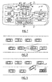
- the system 10 is located within a host vehicle 12 that has a braking system 14 and an engine management system 16.
- System 10 includes a forward-looking sensor 18 for sensing a target in the path of the host vehicle 12.
- the forward-looking sensor 18 generates a range signal corresponding to a distance between the host vehicle 12 and a target and a range rate signal corresponding to a rate said distance between the host vehicle 12 and said target is changing.
- a stop and go controller 20 receives the rate signal and the range rate signal and determines whether to signal the braking system 14 or to signal the engine management system 16 as to maintain a preset distance between the host vehicle 12 and the target.
- the controller 20 maintains the preset distance for host vehicle velocities from zero to 50KPH.
- the system 10 may also include other components such as a driver interface 22, a global positioning system 24, a vehicles dynamics system 26, various indicators 28, and other components as will become more evident from the following description.
- the braking system 14 may include any vehicle system known in the art that is capable of reducing the velocity of the host vehicle 12. Although, the braking system 14 of the present invention comprises two devices 30 for reducing the velocity of the host vehicle 12, other similar systems may be used. For example a transmission controller (not shown) that is capable of downshifting a transmission of the host vehicle 12 may be used to reduce the host vehicle velocity.
- the braking system 14 of the present invention includes a brake booster controller 32 and an electric park brake assist 34.
- the brake booster controller 32 is equivalent to a vehicle operator applying the brakes.
- the electric park brake assist 34 is used when additional braking power is requested by the controller 20.
- the electric park brake assist may be used as a fail-safe mechanism when a failure occurs within the booster (not shown) of the braking system 14.
- the engine management system 16 may include any host vehicle components that adjust the acceleration of the vehicle. These components may include a vehicle accelerator 36 such as in the present invention, a fuel and air intake control system, an engine timing controller, or other vehicle component or system known in the art that may be used to adjust the velocity of the host vehicle 12.
- a vehicle accelerator 36 such as in the present invention
- a fuel and air intake control system such as in the present invention
- an engine timing controller such as in the present invention
- vehicle component or system known in the art may be used to adjust the velocity of the host vehicle 12.
- Forward-looking sensor 18 may be of various type known in the art including a radar sensor, a lidar sensor, a combination of a radar sensor and a camera system or other forward-looking sensor.
- the forward-looking sensor 18 of the present invention is a single frontal mounted sensor, multiple forward-looking sensors mounted at various locations on the host vehicle 12 may be used.
- the forward-looking sensors may be front mounted, side mounted or even rear mounted.
- the purpose of the forward-looking sensor 18 is to sense position and velocity of a target located in a future path of the host vehicle 12 and relative to the host vehicle 12.
- the target may be any of the following: a vehicle, a stopped object, a moving object, a bridge, construction equipment, a sign, an animate or inanimate object, or other object.
- the forward-looking sensor 18 may also gather other information including target angel relative to the host vehicle 12 and yaw rate of the target relative to the host vehicle 12. The additional information allows the controller 20 to more accurately determine the threat of the target as to the host vehicle 12 and the appropriate actions to perform.
- Controller 20 may be a microprocessor based controller such as a computer having a central processing unit, memory (RAM and/or ROM), and associated input and output buses. Controller 20 may be a portion of a main control unit, such as a main vehicle controller, or may be a stand-alone controller.
- the controller 20 of the present invention contains logic for maintaining a preset distance between a target and the host vehicle 12 while operating at a low host vehicle velocity and a midrange host vehicle velocity.
- the low host vehicle velocity includes approximately any velocity below 40KPH, including an at rest velocity of 0KPH.
- the midrange host vehicle velocity includes approximately velocities greater than or equal to 40KPH and less than 50KPH.
- the controller 20 allows an operator to activate the system 10 at any velocity below 50KPH.
- the controller 20 while activated, maintains a preset distance between the host vehicle 12 and the target.
- the preset distance is maintained when the host vehicle velocity is from 0KPH up to 50KPH, from 50KPH down to 0KPH, and any other scenario.
- the controller 20 automatically disengages for host vehicle velocities above 50KPH at which point traditional ACC systems may take over.
- the preset distance may be set by an operator or may be set during production of the system 10.
- the controller 20 may have an initialization hold time, during which the controller 20 holds the host vehicle 12 stationary until an operator reactivates system 10 to resume operation by pressing on the accelerator 36, pressing on a brake pedal (not shown) within the vehicle 12, switching the reengage switch 44, or by another reactivation method known in the art.
- the controller 20 may also hold the host vehicle 12 stationary for a predetermined amount of time after the system 10 reduces the velocity of the host vehicle 12 to a complete stop.
- the controller 20 reactivates the system 10 after the predetermined time has lapsed or waits until the operator re-initializes or deactivates the system 10.
- An embodiment of the present invention includes the driver interface 22 which may have several different switches 39 including a "ON” switch 40, a “Follow” switch 42, a “Reengage” switch 44, or a "Headway” adjustment switch 46.
- the switches 39 allow the operator to activate, deactivate, resume operation, and adjust the distance between the host vehicle 12 and a target.
- the functions that switches 39 perform may be included and automatically implemented through logic within the controller 20.
- the headway adjustment switch 46 may have several settings for example it may have a short, a medium, or a long setting representing different desired set distances that may be maintained between the host vehicle 12 and a target.
- the switches 39 may be of various type and style as known in the art.
- the global positioning system 24 may be incorporated in conjunction with the forward-looking sensor 18 as to detect environment situations, such as an exit ramp, a round-a-bout, or other environmental situations. This is represented by dashed arrow 50.
- the vehicle dynamics system 26 is provided in another embodiment of the present invention, as represented by the dashed arrow 52.
- the vehicle dynamics system 26 uses vehicle sensors (not shown) to measure inertial information of the host vehicle 12. When instability of the host vehicle 12 occurs, the vehicle dynamics system 26 may deactivate the system 10. By deactivating system 10, a false reaction by the controller 10 may be prevented.
- the system 10 may also include various indicators 28 such as an indicator to inform an operator that the system 10 is holding the host vehicle 12 stationary, that acceleration of the host vehicle 12 is being controlled, or that the controller 20 is stopping the host vehicle 12.
- An audible or visual indicator may be provided as to warn the operator that the braking performed by the controller 20 is insufficient to slow down the host vehicle 12 and that the operator should intervene.
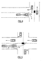
- the host vehicle 12 is using the system 10 in a congested traffic situation.
- the system 10 maintains a preset distance between the host vehicle 12 and a target vehicle 60.
- the host vehicle 12 is using the system 10 while changing lanes to avoid a stopped vehicle 62.
- the system 10 detects a vehicle 64 in the future path of the host vehicle 12 and as in Figure 2 maintains a preset distance between the host vehicle 12 and the detected vehicle 64.
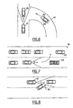
- the host vehicle 12 is using the system 10 while following a target vehicle 66 making a right turn from a complete stop.
- the system 10 may perform several different actions.
- the system 10 may hold the host vehicle 12 stationary until intervention by an operator, the system 10 may detect an oncoming vehicle 68 and also hold the host vehicle 12 stationary until the oncoming vehicle 68 passes, or the system 10 may determine that the oncoming vehicle 68 is at a safe distance and allow the host vehicle 12 to continue following the target vehicle 66.
- Actions are determined in response to detected vehicle positioning and travelling velocities relative to the host vehicle 12.
- the host vehicle 12 is using the system 10 while following a target vehicle 70 making a left turn from a complete stop.
- the system 10 may perform several actions.
- the system 10 will determine vehicle positioning using various detection devices described above as to determine what action to perform. Note when the system 10 encounters a situation that it is not familiar with or is unable to determine what action to perform it may indicate this to the operator and wait for operator intervention.
- the host vehicle 12 is using the system 10 and encountering merging traffic 80 from an entrance ramp 82. Rather than continuing to follow a target vehicle 86 at a preset distance the system 10 may reduce the velocity of the host vehicle 12 as to now follow a new target vehicle 88. Of course, for any of the described situation in this application the controller 20 may be programmed to wait for operator intervention before continuing to act.
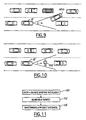
- the host vehicle 12 is using the system 10 while changing lanes in stop and go traffic 90.
- the system 10 may determine to follow a new target vehicle 92 instead of following the original target vehicle 94.
- the host vehicle 12 is using the system 10 and encountering a "cut-in" vehicle 96. Similar to that of Figure 6 the system 1.0 may determine to reduce the velocity of the host vehicle 12 as to let the cut-in vehicle 96 in front of the host vehicle 12 and then resume following the cut-in vehicle 96 at a preset distance.
- the host vehicle 12 is using the system 10 and encountering an oncoming vehicle 100.
- the system 10 may indicate to the operator to intervene and may also reduce the velocity of the host vehicle 12 to zero KPH as to prevent a collision with the oncoming vehicle 100.
- the host vehicle 12 is using the system 10 and encountering a pedestrian 102 or some other object other than another vehicle.
- the system 10 may determine to reduce the velocity of the host vehicle 12 to 0KPH as to prevent colliding with the object 102.
- controller 20 may be programmed to act for other situations.
- FIG. 11 a flow chart illustrating a method of maintaining a preset headway distance between the host vehicle 12 and a target, while travelling at a low or midrange host vehicle velocity of less than 50KPH, in accordance with an embodiment of the present invention is shown.
- step 110 the system 10 is initialized as described above.
- the system 10 is activated and determines the relative positioning and relative velocities of objects surrounding the host vehicle 12. In doing so the system determines the appropriate action to perform.
- step 112 the system 10 senses a target using a detection device such as the forward-looking sensor 18.
- a range signal and a range rate signal are generated corresponding to the distance between the host vehicle 10 and the target and the rate of change of this distance, respectively.
- step 114 the system 10 maintains a preset distance between the host vehicle 12 and the target. This may occur in a couple different situations either the host vehicle 12 is stationary and determines to begin accelerating and following the target or the host vehicle 12 is already travel at a certain velocity and adjusts the host vehicle velocity as to maintain the set distance.
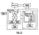
- FIG. 12 a sample state transition diagram illustrating the operation of the system 10 according to an embodiment of the present invention is shown.
- the system 10 is deactivated.
- the system 10 may be sensing objects in a close proximity to the host vehicle 12 as to warn the operator.
- the system 10 In state Stop and Go Standby, the system 10 is in a standby mode. Upon receiving a power on command the system 10 initializes as described above and sits idle until further commanded.
- the system 10 is activated as to follow and maintain a preset distance between the host vehicle 12 and a target.
- the system 10 may act as a traditional cruise control system, illustrated by a Cruise state and corresponding sub states, as known in the art or may perform otherwise depending upon the detection of objects in the close proximity of the host vehicle.
- the system 10 may resort back to the stop and go off state or the stop and go standby state for various reasons as described above.
- a target has been detected and the system maintains the preset distance.
- the preset distance is maintained by four different states, a Stop state, a Go state, a follow Resume state, and an Opening Range state.
- the controller 20 monitors the distance between the host vehicle and the target vehicle as well as the relative range rate to determine an appropriate resolved host vehicle velocity.
- the resolved host vehicle velocity represents a safe host vehicle travelling velocity to maintain the preset distance.
- the host vehicle velocity is greater then the target velocity or the distance between them is less than the preset distance.
- the system 10 reduces the velocity of the host vehicle 12 by signalling the braking system 14.
- the difference between the host vehicle velocity and the resolved host vehicle velocity is less than a predetermined value, or the range rate is less than or equal to a predetermined value and the difference in velocity is greater than or equal to zero.
- the system 10 is signalling the engine management system 16 to not signal the braking system 14. Typically in this state, the host vehicle velocity is approximately equal to the target velocity.
- the system 10 resumes following the target by accelerating or decelerating the vehicle.
- the system 10 returns to the green state.
- the range rate between the host vehicle 12 and the target is greater than a predetermined value and the velocity difference between the host vehicle 12 and the target is less than zero.
- the system 10 reduces the amount that it is accelerating the host vehicle 12 as to prevent a collision.
- the range rate is less than the predetermined value the system 10 returns to the green state.
- the Stop and Go Active state also includes a Follow Override state.
- the Follow Override state is performed when either the operator intervenes, a justified malfunction occurs in a host vehicle system, the braking system is insufficiently reducing the velocity of the host vehicle 12, or for other various reasons that may be envisioned by one skilled in the art.
- a Recover Brake state is also provided when a problem exists in the braking system 14.
- the system 10 indicates to the operator that the system 10 is not able to decelerate the host vehicle 12 because of insufficient braking in the braking system 14.
- the system 10 may apply an emergency brake, such as the electric park brake assist 34, or decelerate the host vehicle 12 using other methods as described above.
- the present invention provides an ACC system that is operable for all host vehicle velocities less than 50KPH.
- the present invention also reduces the amount of tedious actions that an operator has to perform in stop and go traffic.
- the aforementioned reviews how the present invention increases collision-warning capabilities of a host vehicle.
- the above-described apparatus to one skilled in the art, is capable of being adapted for various purposes and is not limited to cruise control systems, forward collision warning systems, collision avoidance systems, vehicle systems but is equally applicable to other systems that may require adaptive speed control.
Landscapes
- Engineering & Computer Science (AREA)
- Transportation (AREA)
- Mechanical Engineering (AREA)
- Automation & Control Theory (AREA)
- Chemical & Material Sciences (AREA)
- Combustion & Propulsion (AREA)
- Traffic Control Systems (AREA)
- Control Of Driving Devices And Active Controlling Of Vehicle (AREA)
Priority Applications (2)
| Application Number | Priority Date | Filing Date | Title |
|---|---|---|---|
| EP03100024A EP1437254B1 (fr) | 2003-01-09 | 2003-01-09 | Régulateur de vitesse avec régulation de la distance entre deux véhicules |
| DE60328255T DE60328255D1 (de) | 2003-01-09 | 2003-01-09 | Abstandsbezogenes Fahrgeschwindigkeitsregelsystem |
Applications Claiming Priority (1)
| Application Number | Priority Date | Filing Date | Title |
|---|---|---|---|
| EP03100024A EP1437254B1 (fr) | 2003-01-09 | 2003-01-09 | Régulateur de vitesse avec régulation de la distance entre deux véhicules |
Publications (2)
| Publication Number | Publication Date |
|---|---|
| EP1437254A1 true EP1437254A1 (fr) | 2004-07-14 |
| EP1437254B1 EP1437254B1 (fr) | 2009-07-08 |
Family
ID=32479939
Family Applications (1)
| Application Number | Title | Priority Date | Filing Date |
|---|---|---|---|
| EP03100024A Expired - Lifetime EP1437254B1 (fr) | 2003-01-09 | 2003-01-09 | Régulateur de vitesse avec régulation de la distance entre deux véhicules |
Country Status (2)
| Country | Link |
|---|---|
| EP (1) | EP1437254B1 (fr) |
| DE (1) | DE60328255D1 (fr) |
Cited By (10)
| Publication number | Priority date | Publication date | Assignee | Title |
|---|---|---|---|---|
| EP1702786A1 (fr) * | 2005-03-16 | 2006-09-20 | Nissan Motor Company Limited | Système de commande de vitesse avec fonctionalité d'arrêt du véhicule |
| EP2130737A3 (fr) * | 2008-06-05 | 2012-02-22 | Volkswagen Ag | Dispositif de freinage pour un véhicule automobile |
| WO2016112946A1 (fr) * | 2015-01-17 | 2016-07-21 | Audi Ag | Procédé permettant de faire fonctionner un véhicule automobile avec un système d'assistance au conducteur longitudinal |
| EP3048024A1 (fr) * | 2015-01-26 | 2016-07-27 | Volvo Car Corporation | Procédé et appareil de régulation adaptative de la vitesse dans un véhicule routier |
| US9789857B2 (en) | 2015-10-22 | 2017-10-17 | Hyundai Motor Company | Apparatus and method of controlling electronic parking brake |
| CN114103942A (zh) * | 2020-08-11 | 2022-03-01 | 通用汽车环球科技运作有限责任公司 | 用于车辆的全速段自适应巡航控制 |
| WO2023274657A1 (fr) | 2021-06-30 | 2023-01-05 | Zf Cv Systems Global Gmbh | Procédé et dispositif de commande de la distance entre un égo-véhicule et un véhicule précédent, véhicule et unité de traitement électronique |
| DE102022102491A1 (de) | 2022-02-02 | 2023-08-03 | Zf Cv Systems Global Gmbh | Verfahren und Vorrichtung zur vorausschauenden Fahrzeugsteuerung für ein Egofahrzeug, sowie Fahrzeug und elektronische Verarbeitungseinheit |
| DE102022112104A1 (de) | 2022-05-13 | 2023-11-16 | Zf Cv Systems Global Gmbh | Verfahren und Vorrichtung zum Verhindern des Auffahrens von einem Egofahrzeug auf ein vorausfahrendes Fahrzeug, sowie Fahrzeug und elektronische Verarbeitungseinheit |
| DE102023210142A1 (de) * | 2023-10-17 | 2025-04-17 | Volkswagen Aktiengesellschaft | Verfahren zum Betreiben einer automatischen Distanzregelung für ein Kraftfahrzeug |
Citations (8)
| Publication number | Priority date | Publication date | Assignee | Title |
|---|---|---|---|---|
| JPS61247526A (ja) * | 1985-04-25 | 1986-11-04 | Mitsubishi Electric Corp | 緩速走行停止装置 |
| US5805103A (en) * | 1995-09-27 | 1998-09-08 | Mazda Motor Corporation | Method of and system for monitoring preceding vehicles |
| EP1065090A2 (fr) * | 1999-06-30 | 2001-01-03 | Nissan Motor Company, Limited | Régulateur de vitesse avec régulation de la distance entre deux véhicules et du couple d'entrainement |
| EP1070624A1 (fr) * | 1999-07-19 | 2001-01-24 | Nissan Motor Company, Limited | Dispositif de suivi d'un véhicule qui le précède |
| DE19952892A1 (de) * | 1999-11-03 | 2001-05-10 | Volkswagen Ag | Fahrzeug mit elektrisch betätigbarer Bremse |
| DE19958520A1 (de) * | 1999-12-04 | 2001-06-07 | Bosch Gmbh Robert | Geschwindigkeitsregler für ein Kraftfahrzeug |
| EP1193106A1 (fr) * | 1999-05-12 | 2002-04-03 | Hitachi, Ltd. | Dispositif de commande de fonctionnement d'un vehicule et vehicule correspondant |
| US20020179355A1 (en) * | 2000-08-03 | 2002-12-05 | Gerhard Kurz | Method and device for automatic speed adjustment in a vehicle |
-
2003
- 2003-01-09 EP EP03100024A patent/EP1437254B1/fr not_active Expired - Lifetime
- 2003-01-09 DE DE60328255T patent/DE60328255D1/de not_active Expired - Lifetime
Patent Citations (8)
| Publication number | Priority date | Publication date | Assignee | Title |
|---|---|---|---|---|
| JPS61247526A (ja) * | 1985-04-25 | 1986-11-04 | Mitsubishi Electric Corp | 緩速走行停止装置 |
| US5805103A (en) * | 1995-09-27 | 1998-09-08 | Mazda Motor Corporation | Method of and system for monitoring preceding vehicles |
| EP1193106A1 (fr) * | 1999-05-12 | 2002-04-03 | Hitachi, Ltd. | Dispositif de commande de fonctionnement d'un vehicule et vehicule correspondant |
| EP1065090A2 (fr) * | 1999-06-30 | 2001-01-03 | Nissan Motor Company, Limited | Régulateur de vitesse avec régulation de la distance entre deux véhicules et du couple d'entrainement |
| EP1070624A1 (fr) * | 1999-07-19 | 2001-01-24 | Nissan Motor Company, Limited | Dispositif de suivi d'un véhicule qui le précède |
| DE19952892A1 (de) * | 1999-11-03 | 2001-05-10 | Volkswagen Ag | Fahrzeug mit elektrisch betätigbarer Bremse |
| DE19958520A1 (de) * | 1999-12-04 | 2001-06-07 | Bosch Gmbh Robert | Geschwindigkeitsregler für ein Kraftfahrzeug |
| US20020179355A1 (en) * | 2000-08-03 | 2002-12-05 | Gerhard Kurz | Method and device for automatic speed adjustment in a vehicle |
Non-Patent Citations (1)
| Title |
|---|
| PATENT ABSTRACTS OF JAPAN vol. 011, no. 098 (M - 575) 27 March 1987 (1987-03-27) * |
Cited By (15)
| Publication number | Priority date | Publication date | Assignee | Title |
|---|---|---|---|---|
| US8078382B2 (en) * | 2005-03-16 | 2011-12-13 | Nissan Motor Co., Ltd. | Cruise and vehicle-following control system including double brakes |
| EP1702786A1 (fr) * | 2005-03-16 | 2006-09-20 | Nissan Motor Company Limited | Système de commande de vitesse avec fonctionalité d'arrêt du véhicule |
| EP2130737A3 (fr) * | 2008-06-05 | 2012-02-22 | Volkswagen Ag | Dispositif de freinage pour un véhicule automobile |
| US10328937B2 (en) | 2015-01-17 | 2019-06-25 | Audi Ag | Method for operating a motor vehicle using a longitudinal driver assistance system |
| WO2016112946A1 (fr) * | 2015-01-17 | 2016-07-21 | Audi Ag | Procédé permettant de faire fonctionner un véhicule automobile avec un système d'assistance au conducteur longitudinal |
| EP3048024A1 (fr) * | 2015-01-26 | 2016-07-27 | Volvo Car Corporation | Procédé et appareil de régulation adaptative de la vitesse dans un véhicule routier |
| US9776509B2 (en) | 2015-01-26 | 2017-10-03 | Volvo Car Corporation | Method and apparatus for adaptive cruise control in a road vehicle |
| US9789857B2 (en) | 2015-10-22 | 2017-10-17 | Hyundai Motor Company | Apparatus and method of controlling electronic parking brake |
| CN114103942A (zh) * | 2020-08-11 | 2022-03-01 | 通用汽车环球科技运作有限责任公司 | 用于车辆的全速段自适应巡航控制 |
| WO2023274657A1 (fr) | 2021-06-30 | 2023-01-05 | Zf Cv Systems Global Gmbh | Procédé et dispositif de commande de la distance entre un égo-véhicule et un véhicule précédent, véhicule et unité de traitement électronique |
| DE102021116853A1 (de) | 2021-06-30 | 2023-01-05 | Zf Cv Systems Global Gmbh | Verfahren und Vorrichtung zum Regeln des Abstandes zwischen einem Egofahrzeug und einem vorausfahrenden Fahrzeug, sowie Fahrzeug und elektronische Verarbeitungseinheit |
| DE102022102491A1 (de) | 2022-02-02 | 2023-08-03 | Zf Cv Systems Global Gmbh | Verfahren und Vorrichtung zur vorausschauenden Fahrzeugsteuerung für ein Egofahrzeug, sowie Fahrzeug und elektronische Verarbeitungseinheit |
| DE102022112104A1 (de) | 2022-05-13 | 2023-11-16 | Zf Cv Systems Global Gmbh | Verfahren und Vorrichtung zum Verhindern des Auffahrens von einem Egofahrzeug auf ein vorausfahrendes Fahrzeug, sowie Fahrzeug und elektronische Verarbeitungseinheit |
| US12447950B2 (en) | 2022-05-13 | 2025-10-21 | Zf Cv Systems Global Gmbh | Method and device for preventing a subject vehicle from driving into a vehicle ahead, as well as vehicle and electronic processing unit |
| DE102023210142A1 (de) * | 2023-10-17 | 2025-04-17 | Volkswagen Aktiengesellschaft | Verfahren zum Betreiben einer automatischen Distanzregelung für ein Kraftfahrzeug |
Also Published As
| Publication number | Publication date |
|---|---|
| EP1437254B1 (fr) | 2009-07-08 |
| DE60328255D1 (de) | 2009-08-20 |
Similar Documents
| Publication | Publication Date | Title |
|---|---|---|
| US6708099B2 (en) | Stop and go adaptive cruise control system | |
| US6560525B1 (en) | Integrated queue assist and adaptive cruise control | |
| US10996672B2 (en) | Driving control apparatus for vehicle | |
| JP7132713B2 (ja) | 車両走行制御装置、車両走行制御システムおよび車両走行制御方法 | |
| JP5715454B2 (ja) | 車両の運転支援装置 | |
| EP3470285B1 (fr) | Dispositif de support d'entraînement | |
| CN111433700B (zh) | 用于基于配属于车队的可预给定的整体运行策略的车队的运动的方法 | |
| US20210163000A1 (en) | Method and system for distance control of a subject vehicle | |
| CN102405162B (zh) | 驾驶辅助装置 | |
| US8396642B2 (en) | Adaptive cruise control system | |
| US7904246B2 (en) | Vehicle driving assist system | |
| US20120283927A1 (en) | Emergency Brake Assistant for Automatically Decelerating a Vehicle to Prevent a Collision or Reduce the Consequences of a Collision | |
| EP3254919A1 (fr) | Système de commande adaptative de la vitesse et véhicule comprenant un système de régulateur de vitesse adaptatif | |
| US20250333051A1 (en) | Driving assistance apparatus | |
| JP5552955B2 (ja) | 車両制御装置 | |
| EP3254918A1 (fr) | Système de commande adaptative de la vitesse et véhicule comprenant un système de régulateur de vitesse adaptatif | |
| KR101552017B1 (ko) | 성능이 개선된 운전보조시스템 및 그 제어방법 | |
| KR102673387B1 (ko) | 운전자 보조 시스템 및 그 제어 방법 | |
| KR20150051548A (ko) | 운전자의 성향을 반영하는 운전보조시스템 및 그 제어방법 | |
| CN103889795B (zh) | 用于运行车辆的行驶动态调节的方法和控制器和调节系统 | |
| US10351132B2 (en) | Control system and control method for driving a motor vehicle | |
| US7715275B2 (en) | Start assist system for motor vehicles | |
| US12263845B2 (en) | Vehicle control apparatus, vehicle, acceleration-and-deceleration control method, and vehicle control program | |
| EP3974277A1 (fr) | Appareil de contrôle de conduite pour véhicule | |
| EP1437254B1 (fr) | Régulateur de vitesse avec régulation de la distance entre deux véhicules |
Legal Events
| Date | Code | Title | Description |
|---|---|---|---|
| PUAI | Public reference made under article 153(3) epc to a published international application that has entered the european phase |
Free format text: ORIGINAL CODE: 0009012 |
|
| AK | Designated contracting states |
Kind code of ref document: A1 Designated state(s): AT BE BG CH CY CZ DE DK EE ES FI FR GB GR HU IE IT LI LU MC NL PT SE SI SK TR |
|
| AX | Request for extension of the european patent |
Extension state: AL LT LV MK RO |
|
| 17P | Request for examination filed |
Effective date: 20050103 |
|
| AKX | Designation fees paid |
Designated state(s): DE FR GB |
|
| 17Q | First examination report despatched |
Effective date: 20071129 |
|
| RIC1 | Information provided on ipc code assigned before grant |
Ipc: B60T 7/22 20060101ALI20081229BHEP Ipc: B60W 30/16 20060101AFI20081229BHEP |
|
| GRAP | Despatch of communication of intention to grant a patent |
Free format text: ORIGINAL CODE: EPIDOSNIGR1 |
|
| GRAS | Grant fee paid |
Free format text: ORIGINAL CODE: EPIDOSNIGR3 |
|
| GRAA | (expected) grant |
Free format text: ORIGINAL CODE: 0009210 |
|
| AK | Designated contracting states |
Kind code of ref document: B1 Designated state(s): DE FR GB |
|
| REG | Reference to a national code |
Ref country code: GB Ref legal event code: FG4D |
|
| REF | Corresponds to: |
Ref document number: 60328255 Country of ref document: DE Date of ref document: 20090820 Kind code of ref document: P |
|
| PLBE | No opposition filed within time limit |
Free format text: ORIGINAL CODE: 0009261 |
|
| STAA | Information on the status of an ep patent application or granted ep patent |
Free format text: STATUS: NO OPPOSITION FILED WITHIN TIME LIMIT |
|
| PGFP | Annual fee paid to national office [announced via postgrant information from national office to epo] |
Ref country code: FR Payment date: 20100125 Year of fee payment: 8 |
|
| 26N | No opposition filed |
Effective date: 20100409 |
|
| REG | Reference to a national code |
Ref country code: FR Ref legal event code: ST Effective date: 20110930 |
|
| PG25 | Lapsed in a contracting state [announced via postgrant information from national office to epo] |
Ref country code: FR Free format text: LAPSE BECAUSE OF NON-PAYMENT OF DUE FEES Effective date: 20110131 |
|
| REG | Reference to a national code |
Ref country code: DE Ref legal event code: R082 Ref document number: 60328255 Country of ref document: DE Representative=s name: DOERFLER, THOMAS, DR.-ING., DE |
|
| PGFP | Annual fee paid to national office [announced via postgrant information from national office to epo] |
Ref country code: GB Payment date: 20191231 Year of fee payment: 18 |
|
| GBPC | Gb: european patent ceased through non-payment of renewal fee |
Effective date: 20210109 |
|
| PG25 | Lapsed in a contracting state [announced via postgrant information from national office to epo] |
Ref country code: GB Free format text: LAPSE BECAUSE OF NON-PAYMENT OF DUE FEES Effective date: 20210109 |
|
| PGFP | Annual fee paid to national office [announced via postgrant information from national office to epo] |
Ref country code: DE Payment date: 20211216 Year of fee payment: 20 |
|
| REG | Reference to a national code |
Ref country code: DE Ref legal event code: R071 Ref document number: 60328255 Country of ref document: DE |