EP1437478A2 - Wärmegedämmtes Verbundprofil - Google Patents
Wärmegedämmtes Verbundprofil Download PDFInfo
- Publication number
- EP1437478A2 EP1437478A2 EP03028334A EP03028334A EP1437478A2 EP 1437478 A2 EP1437478 A2 EP 1437478A2 EP 03028334 A EP03028334 A EP 03028334A EP 03028334 A EP03028334 A EP 03028334A EP 1437478 A2 EP1437478 A2 EP 1437478A2
- Authority
- EP
- European Patent Office
- Prior art keywords
- wall
- groove
- profile
- composite profile
- metallic
- Prior art date
- Legal status (The legal status is an assumption and is not a legal conclusion. Google has not performed a legal analysis and makes no representation as to the accuracy of the status listed.)
- Granted
Links
- 239000002131 composite material Substances 0.000 title claims description 44
- 229910052751 metal Inorganic materials 0.000 claims abstract description 11
- 239000002184 metal Substances 0.000 claims abstract description 11
- 238000009413 insulation Methods 0.000 claims description 12
- 239000000463 material Substances 0.000 claims description 7
- 230000002787 reinforcement Effects 0.000 claims description 4
- 239000000835 fiber Substances 0.000 claims description 2
- 238000003780 insertion Methods 0.000 claims description 2
- 230000037431 insertion Effects 0.000 claims description 2
- 239000011810 insulating material Substances 0.000 claims description 2
- 239000003365 glass fiber Substances 0.000 description 3
- 238000000034 method Methods 0.000 description 2
- 230000000717 retained effect Effects 0.000 description 2
- 229910052782 aluminium Inorganic materials 0.000 description 1
- XAGFODPZIPBFFR-UHFFFAOYSA-N aluminium Chemical compound [Al] XAGFODPZIPBFFR-UHFFFAOYSA-N 0.000 description 1
- 230000015572 biosynthetic process Effects 0.000 description 1
- 239000011521 glass Substances 0.000 description 1
- 238000004519 manufacturing process Methods 0.000 description 1
- 230000003014 reinforcing effect Effects 0.000 description 1
- 239000012779 reinforcing material Substances 0.000 description 1
- 230000008719 thickening Effects 0.000 description 1
Images


Classifications
-
- E—FIXED CONSTRUCTIONS
- E06—DOORS, WINDOWS, SHUTTERS, OR ROLLER BLINDS IN GENERAL; LADDERS
- E06B—FIXED OR MOVABLE CLOSURES FOR OPENINGS IN BUILDINGS, VEHICLES, FENCES OR LIKE ENCLOSURES IN GENERAL, e.g. DOORS, WINDOWS, BLINDS, GATES
- E06B3/00—Window sashes, door leaves, or like elements for closing wall or like openings; Layout of fixed or moving closures, e.g. windows in wall or like openings; Features of rigidly-mounted outer frames relating to the mounting of wing frames
- E06B3/04—Wing frames not characterised by the manner of movement
- E06B3/263—Frames with special provision for insulation
- E06B3/26301—Frames with special provision for insulation with prefabricated insulating strips between two metal section members
-
- E—FIXED CONSTRUCTIONS
- E06—DOORS, WINDOWS, SHUTTERS, OR ROLLER BLINDS IN GENERAL; LADDERS
- E06B—FIXED OR MOVABLE CLOSURES FOR OPENINGS IN BUILDINGS, VEHICLES, FENCES OR LIKE ENCLOSURES IN GENERAL, e.g. DOORS, WINDOWS, BLINDS, GATES
- E06B3/00—Window sashes, door leaves, or like elements for closing wall or like openings; Layout of fixed or moving closures, e.g. windows in wall or like openings; Features of rigidly-mounted outer frames relating to the mounting of wing frames
- E06B3/04—Wing frames not characterised by the manner of movement
- E06B3/263—Frames with special provision for insulation
- E06B2003/26349—Details of insulating strips
- E06B2003/26369—Specific material characteristics
- E06B2003/2637—Specific material characteristics reinforced
-
- E—FIXED CONSTRUCTIONS
- E06—DOORS, WINDOWS, SHUTTERS, OR ROLLER BLINDS IN GENERAL; LADDERS
- E06B—FIXED OR MOVABLE CLOSURES FOR OPENINGS IN BUILDINGS, VEHICLES, FENCES OR LIKE ENCLOSURES IN GENERAL, e.g. DOORS, WINDOWS, BLINDS, GATES
- E06B3/00—Window sashes, door leaves, or like elements for closing wall or like openings; Layout of fixed or moving closures, e.g. windows in wall or like openings; Features of rigidly-mounted outer frames relating to the mounting of wing frames
- E06B3/04—Wing frames not characterised by the manner of movement
- E06B3/263—Frames with special provision for insulation
- E06B2003/26349—Details of insulating strips
- E06B2003/26369—Specific material characteristics
- E06B2003/26374—Specific material characteristics with parts of differing nature
-
- E—FIXED CONSTRUCTIONS
- E06—DOORS, WINDOWS, SHUTTERS, OR ROLLER BLINDS IN GENERAL; LADDERS
- E06B—FIXED OR MOVABLE CLOSURES FOR OPENINGS IN BUILDINGS, VEHICLES, FENCES OR LIKE ENCLOSURES IN GENERAL, e.g. DOORS, WINDOWS, BLINDS, GATES
- E06B3/00—Window sashes, door leaves, or like elements for closing wall or like openings; Layout of fixed or moving closures, e.g. windows in wall or like openings; Features of rigidly-mounted outer frames relating to the mounting of wing frames
- E06B3/04—Wing frames not characterised by the manner of movement
- E06B3/263—Frames with special provision for insulation
- E06B2003/26349—Details of insulating strips
- E06B2003/26387—Performing extra functions
- E06B2003/26389—Holding sealing strips or forming sealing abutments
-
- E—FIXED CONSTRUCTIONS
- E06—DOORS, WINDOWS, SHUTTERS, OR ROLLER BLINDS IN GENERAL; LADDERS
- E06B—FIXED OR MOVABLE CLOSURES FOR OPENINGS IN BUILDINGS, VEHICLES, FENCES OR LIKE ENCLOSURES IN GENERAL, e.g. DOORS, WINDOWS, BLINDS, GATES
- E06B3/00—Window sashes, door leaves, or like elements for closing wall or like openings; Layout of fixed or moving closures, e.g. windows in wall or like openings; Features of rigidly-mounted outer frames relating to the mounting of wing frames
- E06B3/04—Wing frames not characterised by the manner of movement
- E06B3/263—Frames with special provision for insulation
- E06B2003/26349—Details of insulating strips
- E06B2003/26387—Performing extra functions
- E06B2003/2639—Provisions for fittings, e.g. locks or hinges
Definitions
- the present invention relates to a thermally insulated composite profile, in particular to form frames for windows, doors, facade elements or the like, with a metallic profile on a first side and a metallic one Profile on an opposite second side, and at least one plastic containing insulating web, which the two metallic profiles under training a thermal insulation zone connects, with at least one groove for Inclusion of a fitting part or fastener is provided.
- thermally insulated composite profile is known, the two Has profiles made of metal, which are connected to one another via insulating rods.
- the Profiles made of metal have grooves in which fittings can be inserted, so that the profiles form a frame for windows or doors to let.
- the use of insulating webs ensures for a certain thermal insulation, but the insulating bars are relative trained short and therefore create only a limited heat insulation.
- a Widening of the insulating webs leads to an improvement in thermal insulation, but also leads to a greater depth of the frame profiles themselves. This greater Profile depth leads to functional restrictions of the windows formed from it, in particular, the smallest dimensions of the windows are restricted.
- the composite profile has a groove for receiving a fitting part or fastener, the first wall through an outer wall or a wall adjacent to the outer wall of a metallic profile and the second wall opposite the first wall is integrally formed on the insulating web is.
- the groove is thus made of a metallic part and a part on the insulating web formed so that the length of the insulating web is comparatively longer can be what increases the thermal insulation.
- the functionality of the Composite profile is maintained by the formation of such a groove, since the known fittings can be used in the groove, so that none mechanical disadvantages have to be accepted or other stability problems occur.
- the depth of the composite profile can also be maintained become.
- the groove is undercut trained and both on the metal outer wall or an adjacent Wall as well as on the second wall is one to the median plane the groove directed protruding bar provided. This allows hardware components, how locking bars are inserted into the composite profile and are against secured from falling out.
- the fittings can be particularly well in the groove be performed. Small changes in height on the ground can usually still be compensated are, however, the fittings are often symmetrical in cross section, so that the groove is also preferably symmetrical on the guide surfaces is trained.
- the second wall is the groove for a particularly stable guidance of fittings increasingly trained.
- the reinforcement can be by embedded fibers and / or inlays made of a reinforcing material, for example glass fibers, metal or others Materials. Additionally or alternatively, the second wall can be on the side facing away from the first wall can also be supported by a strut to be able to absorb high mechanical loads. If the strut is slanted runs and is connected to the insulating web, the insulating web can also be used as Manufacture part of a hollow profile.
- the second wall it is also possible to use the second wall to train in several parts. There can also be reinforcement pads on the groove wall be provided, which ensure an even distribution of forces.
- the composite profile is a frame profile formed and each metallic profile has at least one hollow chamber Insertion of a corner connector. This allows particularly stable frames for doors or windows. In the groove, the dimensions of which are retained can then insert a locking bar and / or another fitting part so that the frame also provides good thermal insulation with high stability has.
- a composite profile 1 for a casement comprises a metallic profile 2 and a metallic profile 3, which are extruded from aluminum, for example. Between the profiles 2 and 3, two insulating webs 4 and 5 are arranged, the on known fastening techniques with profiles 2 and 3 permanently connected are.
- a groove 6 is provided on the metal profile 3 and the insulating web 4, wherein a first wall 7 of the groove 6 is formed by the outer wall of the profile 3.
- the Groove 6 can also be parallel by a dashed metallic wall 16 and be limited laterally close to the wall 7.
- a second wall 9 of the groove 6 is formed on the insulating web 4.
- the groove 6 is undercut, with a bar from the outer wall 7 8 and from the wall 9 a strip 10 each protrude inwards towards the center of the groove. Due to the strips 8 and 10, a fitting part 11 is captive in the groove 6 added, the strip 8 being stepped and the fitting part 11 does not run directly on the outer wall 7.
- the bottom of the groove 6 is partially through a metallic section 12 of the profile 3 and partially through a section 13 of the insulating web 4 is formed, by enclosing a thickened section 17 of the insulating web 4 by means of a rolled web 18 a small depression is provided in the bottom, which, however, the functionality of the groove 6th not affected.
- Section 13 can also be extended as required and, if necessary, the section 12 of the metallic profile 3 can be shortened.
- the length of the section 12 depends on the composite profile 1 shown Size of the hollow chamber 14 from, for example, for receiving a corner connector is used.
- FIG. 1B shows a comparable composite profile 1 according to the prior art with a metallic profile 2 'and a metallic profile 3', the insulating webs 4 'and 5' are interconnected.
- a groove 6 ' is provided, the groove walls 7' and 9 'of which are made of metal and which is also undercut, inwardly projecting strips 8 ' and 10 'are provided.
- the length of the insulating webs 4 'and 5' is only A ', so that only a limited one Thermal insulation is given.
- the length of the insulating webs 4 and 5 is in each case A. and is significantly longer than in the prior art. This creates thermal insulation the composite profile 1 improved without increasing its width. Furthermore, the functionality of the composite profile 1 is retained, since all Cavities 14, 15 and corresponding grooves 6 for the use of existing ones Fasteners and fittings can be used.
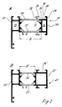
- FIG. 2A A further composite profile 21 for a window frame is shown in FIG. 2A.
- the Composite profile 21 comprises a metallic profile 22, which has insulating webs 24 and 25 is connected to a further metallic profile 23.
- the groove 26 is again undercut and includes inwardly protruding Last 28 and 30.
- the bottom of the groove 26 is through a metallic section 32 of the profile 23 and a section 33 of the insulating web 24 are formed.
- In the metallic Profile 23 is a hollow chamber 34 and one in the metallic profile 22 additional hollow chamber 35 is provided, into which fasteners can be inserted.
- the width of the thermal insulation zone formed by the insulating webs 24 and 25 is B.
- FIG 2 B is a comparable composite profile 21 'after State of the art shown.
- the composite profile 21 ' comprises a metallic profile 22 ', with insulating webs 24' and 25 'with the further metallic profile 23' connected is.
- a groove 26 ' is formed on the metallic profile 23'.
- the for Area of insulating strips 24 'and 25' available for thermal insulation has only the length B 'and is significantly smaller than in the invention Embodiment, even if the functionality of the composite profile 21 compared the composite profile 21 'of the prior art is maintained.
- FIG. 3 shows an insulating profile 40 made of plastic or a composite material, that can be used in a composite profile according to the invention.
- the insulating profile 40 comprises an insulating web 41 on the respective thickened ends 42 and 43 are formed on webs of a metal profile for a Permanent connection can be edged.
- the thickening 42 and 43 each have knurled wires 44 which provide the shear strength between Isoliersteg 41 and the respective metallic outer profile by positive locking improve.
- the groove wall 46 and the bar 47 are supported by a strut 48 extending on the side facing away from the groove, so that increased mechanical loads are also absorbed by the groove wall 46 can be.
- On the strut 48 is also a bar 49 as an attachment for molded a seal.
- FIG. 4 shows a composite profile according to the invention in the assembled state.
- a metallic profile 2 is an insulating profile with an insulating web 41 'and one Insulating web 5 connected to another metallic profile 3.
- the composite profile is part of a frame of a wing in which an insulating glass pane 55 is bordered.
- a groove 6 is provided, which as in the previous ones Embodiments has a wall through the outer wall of the metallic profile 3 is formed and on the opposite side Has wall, which is integrally formed on the insulating profile.
- the wall is on the side of the insulating profile is formed in several parts and comprises a holding section 46 ' the material of the insulating profile and an insert 51 which is edged on the insulating profile is.
- An inwardly projecting strip 52 is formed on the insert 51, so that a fitting part can be inserted captively into the groove 6.
- the wall 46 ' is supported by a strut 48' which is connected to the insulating web 41 '.
- a stop 49 'for a seal 50 is formed on the strut 48'.
- the frame is according to the state of the Technique with a metallic profile 22 'and a metallic profile 23', the are connected via insulating webs 24 'and 25'. It is also possible, an inventive composite profile according to FIG. 2A also for the window frame use.
- the size of the cavities in the metal profiles mostly from the stability requirements and the intended fasteners, like corner connector, depending. This is the area of the groove bottom, which is formed by the insulating web, relatively small. It is also possible that Extend insulating bars in other mechanical conditions. The groove dimensions and the depth of the profile can be maintained.
- the insulating webs are made of a plastic material, which is made of glass fibers or other materials can be reinforced. It is also possible to replace the deposit 51 form or insert an insert in the form of glass fiber inlays into the insulating profile or to provide other additional reinforcing means.
Landscapes
- Engineering & Computer Science (AREA)
- Civil Engineering (AREA)
- Structural Engineering (AREA)
- Wing Frames And Configurations (AREA)
- Door And Window Frames Mounted To Openings (AREA)
- Thermal Insulation (AREA)
- Building Environments (AREA)
- Moulding By Coating Moulds (AREA)
- Laminated Bodies (AREA)
- Superconductors And Manufacturing Methods Therefor (AREA)
- Insulated Conductors (AREA)
- Insulating Bodies (AREA)
Abstract
Description
- Figur 1 A
- eine geschnittene Querschnittsansicht durch ein erfindungsgemäßes Verbundprofil gemäß einem ersten Ausführungsbeispiel;
- Figur 1 B
- eine geschnittene Querschnittsansicht eines Verbundprofils ähnlich zu Figur 1 A gemäß dem Stand der Technik;
- Figur 2 A
- eine geschnittene Querschnittsansicht eines zweiten Ausführungsbeispiels eines erfindungsgemäßen Verbundprofils;
- Figur 2 B
- eine geschnittene Querschnittsansicht eines Verbundprofils ähnlich zu Figur 2 A gemäß dem Stand der Technik;
- Figur 3
- eine Querschnittsansicht eines modifizierten Isoliersteges für ein erfindungsgemäßes Verbundprofil, und
- Figur 4
- eine Querschnittsansicht eines erfindungsgemäßen Verbundprofils mit modifizierter Isolierleiste im montierten Zustand.
Claims (10)
- Wärmegedämmtes Verbundprofil (1, 21), insbesondere zur Bildung von Rahmen für Fenster, Türen, Fassadenelementen oder dergleichen, mit einem metallischen Profil (3, 23) auf einer ersten Seite und einem metallischen Profil (2, 22) auf einer gegenüberliegenden zweiten Seite, und mindestens einem Kunststoff enthaltenden Isoliersteg (4, 24, 41) der die beiden metallischen Profile (2, 3, 22, 23) unter Ausbildung einer Wärmedämmzone miteinander verbindet, wobei mindestens eine Nut (6, 26) zur Aufnahme eines Beschlagteiles (11) oder Befestigungselementes vorgesehen ist, dadurch gekennzeichnet, dass die Nut (6, 26) eine erste Wand (7, 27) aufweist, die durch eine Außenwand oder eine Wand (16) benachbart zur Außenwand eines metallischen Profils (3, 23) gebildet ist, und eine zweite der ersten Wand (7, 27) gegenüberliegenden Wand (9, 29, 46) aufweist, die an dem Isoliersteg (4, 24, 41) angeformt ist.
- Verbundprofil nach Anspruch 1, dadurch gekennzeichnet, dass die Nut (6, 26) hinterschnitten ausgebildet ist und sowohl an der metallischen Außenwand (7, 27) als auch an der zweiten Wand (9, 29, 46) eine zur Mittelebene der Nut (6, 26) gerichtete hervorstehende Leiste (8, 10, 28, 30, 47, 52) vorgesehen ist.
- Verbundprofil nach Anspruch 1 oder 2, dadurch gekennzeichnet, dass der Boden der Nut (6, 26) teilweise aus Isoliermaterial und teilweise aus Metall gebildet ist und die Bereiche mit unterschiedlichen Materialien im wesentlichen auf einer Ebene angeordnet sind.
- Verbundprofil nach einem der Ansprüche 1 bis 3, dadurch gekennzeichnet, dass die zweite Wand (9, 29, 46) der Nut (6, 26) verstärkt ausgebildet ist.
- Verbundprofil nach Anspruch 4, dadurch gekennzeichnet, dass die Verstärkung der zweiten Wand (9, 29, 46) durch ein- oder angelagerte Fasern und/oder Inlays aus einem Verstärkungsmaterial erfolgt.
- Verbundprofil nach Anspruch 4 oder 5, dadurch gekennzeichnet, dass die zweite Wand (46) auf der zur ersten Wand abgewandten Seite durch eine Strebe (48) abgestützt ist.
- Verbundprofil nach einem der Ansprüche 1 bis 6, dadurch gekennzeichnet, dass der Isoliersteg (41) Teil eines Hohlprofils aus Kunststoff ist.
- Verbundprofil nach einem der Ansprüche 1 bis 7, dadurch gekennzeichnet, dass die zweite Wand (46', 51) mehrteilig ausgebildet ist.
- Verbundprofil nach einem der Ansprüche 1 bis 8, dadurch gekennzeichnet, dass das Verbundprofil (1, 21) als Rahmenprofil ausgebildet ist und jedes metallische Profil (2, 3, 22, 23) mindestens eine Hohlkammer (14, 15, 34, 35) zur Einfügung eines Eckverbinders aufweist.
- Verbundprofil nach einem der Ansprüche 1 bis 9, dadurch gekennzeichnet, dass in die Nut (6, 26) eine Riegelstange (11) und/oder ein anderes Beschlagteil eingefügt ist.
Applications Claiming Priority (2)
| Application Number | Priority Date | Filing Date | Title |
|---|---|---|---|
| DE10300860A DE10300860A1 (de) | 2003-01-10 | 2003-01-10 | Wärmegedämmtes Verbundprofil |
| DE10300860 | 2003-01-10 |
Publications (3)
| Publication Number | Publication Date |
|---|---|
| EP1437478A2 true EP1437478A2 (de) | 2004-07-14 |
| EP1437478A3 EP1437478A3 (de) | 2005-04-20 |
| EP1437478B1 EP1437478B1 (de) | 2009-07-22 |
Family
ID=32478215
Family Applications (1)
| Application Number | Title | Priority Date | Filing Date |
|---|---|---|---|
| EP03028334A Expired - Lifetime EP1437478B1 (de) | 2003-01-10 | 2003-12-10 | Wärmegedämmtes Verbundprofil |
Country Status (5)
| Country | Link |
|---|---|
| EP (1) | EP1437478B1 (de) |
| AT (1) | ATE437286T1 (de) |
| DE (2) | DE10300860A1 (de) |
| DK (1) | DK1437478T3 (de) |
| ES (1) | ES2329455T3 (de) |
Cited By (4)
| Publication number | Priority date | Publication date | Assignee | Title |
|---|---|---|---|---|
| DE102005032176A1 (de) * | 2005-07-09 | 2007-01-11 | Hydro Building Systems Gmbh | Wärmegedämmtes Verbundprofil |
| ES2302570A1 (es) * | 2005-03-18 | 2008-07-16 | Aluminios Cortizo, S.A. | Canal determinado entre el marco fijo y el marco movil de una hoja de ventana y/o puerta en carpinteria metalica. |
| ES2303779A1 (es) * | 2007-02-01 | 2008-08-16 | Fernando Fraguas Esteban | Sistema para la realizacion de marcos metalicos de ventanas y puertas de apertura corredera con aislamiento termico mejorado. |
| EP2532819A1 (de) * | 2011-06-06 | 2012-12-12 | Dorma GmbH + Co. KG | Türrahmen |
Families Citing this family (3)
| Publication number | Priority date | Publication date | Assignee | Title |
|---|---|---|---|---|
| DE102007025138A1 (de) * | 2007-05-30 | 2008-12-11 | Norsk Hydro Asa | Wärmegedämmtes Verbundprofil für Fenster, Türen, Fassaden und dergleichen |
| DE202013105457U1 (de) | 2012-11-30 | 2013-12-05 | Akotherm Gmbh | Profilanordnung, insbesondere für eine Tür oder ein Fenster |
| DE102014115422A1 (de) * | 2014-10-23 | 2016-04-28 | SCHÜCO International KG | Fenster oder Tür, insbesondere Blockfenster |
Citations (1)
| Publication number | Priority date | Publication date | Assignee | Title |
|---|---|---|---|---|
| DE3316624A1 (de) | 1983-05-06 | 1984-11-08 | SCHÜCO Heinz Schürmann GmbH & Co, 4800 Bielefeld | Isolierstab fuer ein waermegedaemmtes verbundprofil fuer fenster, tueren oder fassaden |
Family Cites Families (7)
| Publication number | Priority date | Publication date | Assignee | Title |
|---|---|---|---|---|
| DE3624849A1 (de) * | 1986-07-23 | 1988-01-28 | Schuermann & Co Heinz | Fenster, tuer oder festverglasung in beschusshemmender ausfuehrung |
| IT1244415B (it) * | 1990-06-07 | 1994-07-14 | Valcasa Srl | Serie omogenea di profili per serramenti in alluminio |
| DE29616617U1 (de) * | 1995-09-27 | 1996-12-05 | W. Hartmann & Co (Gmbh & Co), 20459 Hamburg | Wärmegedämmtes Verbundprofil |
| DE29701026U1 (de) * | 1996-01-25 | 1997-05-07 | W. Hartmann & Co (Gmbh & Co), 20459 Hamburg | Falzdämmprofil |
| FR2760036B1 (fr) * | 1997-02-21 | 1999-05-14 | Ouest Alu | Fenetre ou porte-fenetre a frappe, a ouvrant(s) cache(s) |
| DE20100619U1 (de) * | 2001-01-12 | 2001-03-08 | Schüco International KG, 33609 Bielefeld | Glasflügel |
| DE10116049B4 (de) * | 2001-03-30 | 2016-10-06 | Ensinger Gmbh | Verwendung eines Kunststoffprofils und Verfahren zur Herstellung desselben |
-
2003
- 2003-01-10 DE DE10300860A patent/DE10300860A1/de not_active Withdrawn
- 2003-12-10 AT AT03028334T patent/ATE437286T1/de active
- 2003-12-10 EP EP03028334A patent/EP1437478B1/de not_active Expired - Lifetime
- 2003-12-10 DE DE50311726T patent/DE50311726D1/de not_active Expired - Lifetime
- 2003-12-10 DK DK03028334T patent/DK1437478T3/da active
- 2003-12-10 ES ES03028334T patent/ES2329455T3/es not_active Expired - Lifetime
Patent Citations (1)
| Publication number | Priority date | Publication date | Assignee | Title |
|---|---|---|---|---|
| DE3316624A1 (de) | 1983-05-06 | 1984-11-08 | SCHÜCO Heinz Schürmann GmbH & Co, 4800 Bielefeld | Isolierstab fuer ein waermegedaemmtes verbundprofil fuer fenster, tueren oder fassaden |
Cited By (6)
| Publication number | Priority date | Publication date | Assignee | Title |
|---|---|---|---|---|
| ES2302570A1 (es) * | 2005-03-18 | 2008-07-16 | Aluminios Cortizo, S.A. | Canal determinado entre el marco fijo y el marco movil de una hoja de ventana y/o puerta en carpinteria metalica. |
| ES2302570B1 (es) * | 2005-03-18 | 2009-05-19 | Aluminios Cortizo, S.A. | Canal determinado entre el marco fijo y el marco movil de una hoja de ventana y/o puerta en carpinteria metalica. |
| DE102005032176A1 (de) * | 2005-07-09 | 2007-01-11 | Hydro Building Systems Gmbh | Wärmegedämmtes Verbundprofil |
| ES2303779A1 (es) * | 2007-02-01 | 2008-08-16 | Fernando Fraguas Esteban | Sistema para la realizacion de marcos metalicos de ventanas y puertas de apertura corredera con aislamiento termico mejorado. |
| ES2303779B1 (es) * | 2007-02-01 | 2009-05-01 | Fernando Fraguas Esteban | Sistema para la realizacion de marcos metalicos de ventanas y puertas de apertura corredera con aislamiento termico mejorado. |
| EP2532819A1 (de) * | 2011-06-06 | 2012-12-12 | Dorma GmbH + Co. KG | Türrahmen |
Also Published As
| Publication number | Publication date |
|---|---|
| DE50311726D1 (de) | 2009-09-03 |
| DE10300860A1 (de) | 2004-07-22 |
| EP1437478A3 (de) | 2005-04-20 |
| DK1437478T3 (da) | 2009-11-09 |
| EP1437478B1 (de) | 2009-07-22 |
| ATE437286T1 (de) | 2009-08-15 |
| ES2329455T3 (es) | 2009-11-26 |
Similar Documents
| Publication | Publication Date | Title |
|---|---|---|
| EP0009652B1 (de) | Bausatz für vertikale oder horizontale Schiebefenster | |
| EP1352134B1 (de) | Riegel-pfosten-konstruktion | |
| EP2240662A1 (de) | Verwendung eines faserverstärkten kunststoffs als armierung eines profils für fenster- oder türrahmen | |
| EP0153758A2 (de) | Verbundstab, insbesondere für Fensterrahmen, Türrahmen und Rolläden | |
| CH649809A5 (de) | Aluminium-verbundprofil und mit diesem hergestellte fenster- oder tuerkonstruktion. | |
| AT396384B (de) | Metallprofile zur herstellung von tueren und fenstern und aehnlichem | |
| EP0202510A2 (de) | Blend- oder Flügelrahmen für Fenster oder Türen | |
| EP1437478B1 (de) | Wärmegedämmtes Verbundprofil | |
| DE3200844A1 (de) | Waermedaemmendes verbundprofil | |
| AT398328B (de) | Verbund-profilstab mit zwei metallischen stäben und einem diese verbindenden isolierstab sowie rahmen mit schenkeln, die je einen verbund-profilstab aufweisen | |
| AT390473B (de) | Profilrahmen fuer schiebetueren oder -fenster | |
| DE102008020988A1 (de) | Wärmeisolierendes Rahmenprofil für die Herstellung von Tür- und Fensterrahmen | |
| EP3591158B1 (de) | Bauelement | |
| DE10028802A1 (de) | Bauelement und Verwendung eines Trägers sowie Verfahren zur Herstellung eines Fassadenelementes | |
| DE19804222C2 (de) | Isoliersteg für Verbundprofile von Fenster- oder Türrahmen | |
| CH624449A5 (en) | Device for connecting a covering frame to a base frame for windows, facades or room partitions | |
| DE20100618U1 (de) | Rahmenprofil | |
| EP3140484B1 (de) | Verbundprofil für türen, fenster oder fassadenelemente | |
| DE202013100101U1 (de) | Wärmedämmleiste und Rahmenprofil für ein Fenster, eine Tür, eine Fassade oder ein Lichtdach | |
| EP0906999A2 (de) | Isoliersteg für Verbundprofile von Fenster- oder Türrahmen | |
| EP3626927B1 (de) | Verbundprofil für fenster und/oder türen | |
| EP3336296B1 (de) | Glasklotzbrücke sowie diese umfassender fenster- oder türflügel | |
| EP3150792B1 (de) | Thermisch getrenntes profilrahmensystem | |
| EP4424968B1 (de) | Verbundprofil, rahmen und verfahren zur herstellung des verbundprofils | |
| DE102014112145A1 (de) | Verbundprofil für Türen, Fenster oder Fassadenelemente |
Legal Events
| Date | Code | Title | Description |
|---|---|---|---|
| PUAI | Public reference made under article 153(3) epc to a published international application that has entered the european phase |
Free format text: ORIGINAL CODE: 0009012 |
|
| AK | Designated contracting states |
Kind code of ref document: A2 Designated state(s): AT BE BG CH CY CZ DE DK EE ES FI FR GB GR HU IE IT LI LU MC NL PT RO SE SI SK TR |
|
| AX | Request for extension of the european patent |
Extension state: AL LT LV MK |
|
| PUAL | Search report despatched |
Free format text: ORIGINAL CODE: 0009013 |
|
| AK | Designated contracting states |
Kind code of ref document: A3 Designated state(s): AT BE BG CH CY CZ DE DK EE ES FI FR GB GR HU IE IT LI LU MC NL PT RO SE SI SK TR |
|
| AX | Request for extension of the european patent |
Extension state: AL LT LV MK |
|
| 17P | Request for examination filed |
Effective date: 20050708 |
|
| AKX | Designation fees paid |
Designated state(s): AT BE BG CH CY CZ DE DK EE ES FI FR GB GR HU IE IT LI LU MC NL PT RO SE SI SK TR |
|
| AXX | Extension fees paid |
Extension state: LV Payment date: 20050708 Extension state: LT Payment date: 20050708 |
|
| 17Q | First examination report despatched |
Effective date: 20080310 |
|
| GRAP | Despatch of communication of intention to grant a patent |
Free format text: ORIGINAL CODE: EPIDOSNIGR1 |
|
| GRAS | Grant fee paid |
Free format text: ORIGINAL CODE: EPIDOSNIGR3 |
|
| GRAA | (expected) grant |
Free format text: ORIGINAL CODE: 0009210 |
|
| AK | Designated contracting states |
Kind code of ref document: B1 Designated state(s): AT BE BG CH CY CZ DE DK EE ES FI FR GB GR HU IE IT LI LU MC NL PT RO SE SI SK TR |
|
| AX | Request for extension of the european patent |
Extension state: LT LV |
|
| REG | Reference to a national code |
Ref country code: GB Ref legal event code: FG4D Free format text: NOT ENGLISH |
|
| REG | Reference to a national code |
Ref country code: CH Ref legal event code: EP |
|
| REG | Reference to a national code |
Ref country code: IE Ref legal event code: FG4D |
|
| REF | Corresponds to: |
Ref document number: 50311726 Country of ref document: DE Date of ref document: 20090903 Kind code of ref document: P |
|
| REG | Reference to a national code |
Ref country code: CH Ref legal event code: NV Representative=s name: KATZAROV S.A. |
|
| REG | Reference to a national code |
Ref country code: SE Ref legal event code: TRGR |
|
| REG | Reference to a national code |
Ref country code: DK Ref legal event code: T3 |
|
| REG | Reference to a national code |
Ref country code: ES Ref legal event code: FG2A Ref document number: 2329455 Country of ref document: ES Kind code of ref document: T3 |
|
| LTIE | Lt: invalidation of european patent or patent extension |
Effective date: 20090722 |
|
| PG25 | Lapsed in a contracting state [announced via postgrant information from national office to epo] |
Ref country code: FI Free format text: LAPSE BECAUSE OF FAILURE TO SUBMIT A TRANSLATION OF THE DESCRIPTION OR TO PAY THE FEE WITHIN THE PRESCRIBED TIME-LIMIT Effective date: 20090722 |
|
| PG25 | Lapsed in a contracting state [announced via postgrant information from national office to epo] |
Ref country code: SI Free format text: LAPSE BECAUSE OF FAILURE TO SUBMIT A TRANSLATION OF THE DESCRIPTION OR TO PAY THE FEE WITHIN THE PRESCRIBED TIME-LIMIT Effective date: 20090722 |
|
| REG | Reference to a national code |
Ref country code: IE Ref legal event code: FD4D |
|
| PG25 | Lapsed in a contracting state [announced via postgrant information from national office to epo] |
Ref country code: PT Free format text: LAPSE BECAUSE OF FAILURE TO SUBMIT A TRANSLATION OF THE DESCRIPTION OR TO PAY THE FEE WITHIN THE PRESCRIBED TIME-LIMIT Effective date: 20091122 Ref country code: BG Free format text: LAPSE BECAUSE OF FAILURE TO SUBMIT A TRANSLATION OF THE DESCRIPTION OR TO PAY THE FEE WITHIN THE PRESCRIBED TIME-LIMIT Effective date: 20091022 |
|
| PG25 | Lapsed in a contracting state [announced via postgrant information from national office to epo] |
Ref country code: EE Free format text: LAPSE BECAUSE OF FAILURE TO SUBMIT A TRANSLATION OF THE DESCRIPTION OR TO PAY THE FEE WITHIN THE PRESCRIBED TIME-LIMIT Effective date: 20090722 Ref country code: RO Free format text: LAPSE BECAUSE OF FAILURE TO SUBMIT A TRANSLATION OF THE DESCRIPTION OR TO PAY THE FEE WITHIN THE PRESCRIBED TIME-LIMIT Effective date: 20090722 Ref country code: IE Free format text: LAPSE BECAUSE OF FAILURE TO SUBMIT A TRANSLATION OF THE DESCRIPTION OR TO PAY THE FEE WITHIN THE PRESCRIBED TIME-LIMIT Effective date: 20090722 Ref country code: CZ Free format text: LAPSE BECAUSE OF FAILURE TO SUBMIT A TRANSLATION OF THE DESCRIPTION OR TO PAY THE FEE WITHIN THE PRESCRIBED TIME-LIMIT Effective date: 20090722 |
|
| PLBE | No opposition filed within time limit |
Free format text: ORIGINAL CODE: 0009261 |
|
| STAA | Information on the status of an ep patent application or granted ep patent |
Free format text: STATUS: NO OPPOSITION FILED WITHIN TIME LIMIT |
|
| PG25 | Lapsed in a contracting state [announced via postgrant information from national office to epo] |
Ref country code: SK Free format text: LAPSE BECAUSE OF FAILURE TO SUBMIT A TRANSLATION OF THE DESCRIPTION OR TO PAY THE FEE WITHIN THE PRESCRIBED TIME-LIMIT Effective date: 20090722 |
|
| 26N | No opposition filed |
Effective date: 20100423 |
|
| PG25 | Lapsed in a contracting state [announced via postgrant information from national office to epo] |
Ref country code: MC Free format text: LAPSE BECAUSE OF NON-PAYMENT OF DUE FEES Effective date: 20100701 |
|
| PG25 | Lapsed in a contracting state [announced via postgrant information from national office to epo] |
Ref country code: GR Free format text: LAPSE BECAUSE OF FAILURE TO SUBMIT A TRANSLATION OF THE DESCRIPTION OR TO PAY THE FEE WITHIN THE PRESCRIBED TIME-LIMIT Effective date: 20091023 |
|
| PGFP | Annual fee paid to national office [announced via postgrant information from national office to epo] |
Ref country code: DK Payment date: 20101223 Year of fee payment: 8 |
|
| PGFP | Annual fee paid to national office [announced via postgrant information from national office to epo] |
Ref country code: SE Payment date: 20101221 Year of fee payment: 8 |
|
| PG25 | Lapsed in a contracting state [announced via postgrant information from national office to epo] |
Ref country code: LU Free format text: LAPSE BECAUSE OF NON-PAYMENT OF DUE FEES Effective date: 20091210 |
|
| PG25 | Lapsed in a contracting state [announced via postgrant information from national office to epo] |
Ref country code: HU Free format text: LAPSE BECAUSE OF FAILURE TO SUBMIT A TRANSLATION OF THE DESCRIPTION OR TO PAY THE FEE WITHIN THE PRESCRIBED TIME-LIMIT Effective date: 20100123 |
|
| PG25 | Lapsed in a contracting state [announced via postgrant information from national office to epo] |
Ref country code: TR Free format text: LAPSE BECAUSE OF FAILURE TO SUBMIT A TRANSLATION OF THE DESCRIPTION OR TO PAY THE FEE WITHIN THE PRESCRIBED TIME-LIMIT Effective date: 20090722 |
|
| PG25 | Lapsed in a contracting state [announced via postgrant information from national office to epo] |
Ref country code: CY Free format text: LAPSE BECAUSE OF FAILURE TO SUBMIT A TRANSLATION OF THE DESCRIPTION OR TO PAY THE FEE WITHIN THE PRESCRIBED TIME-LIMIT Effective date: 20090722 |
|
| REG | Reference to a national code |
Ref country code: DK Ref legal event code: EBP |
|
| REG | Reference to a national code |
Ref country code: SE Ref legal event code: EUG |
|
| PG25 | Lapsed in a contracting state [announced via postgrant information from national office to epo] |
Ref country code: SE Free format text: LAPSE BECAUSE OF NON-PAYMENT OF DUE FEES Effective date: 20111211 |
|
| PG25 | Lapsed in a contracting state [announced via postgrant information from national office to epo] |
Ref country code: DK Free format text: LAPSE BECAUSE OF NON-PAYMENT OF DUE FEES Effective date: 20120102 |
|
| REG | Reference to a national code |
Ref country code: FR Ref legal event code: PLFP Year of fee payment: 13 |
|
| REG | Reference to a national code |
Ref country code: FR Ref legal event code: PLFP Year of fee payment: 14 |
|
| PGFP | Annual fee paid to national office [announced via postgrant information from national office to epo] |
Ref country code: CH Payment date: 20161222 Year of fee payment: 14 |
|
| PGFP | Annual fee paid to national office [announced via postgrant information from national office to epo] |
Ref country code: AT Payment date: 20161219 Year of fee payment: 14 |
|
| REG | Reference to a national code |
Ref country code: FR Ref legal event code: PLFP Year of fee payment: 15 |
|
| PGFP | Annual fee paid to national office [announced via postgrant information from national office to epo] |
Ref country code: NL Payment date: 20171219 Year of fee payment: 15 |
|
| REG | Reference to a national code |
Ref country code: CH Ref legal event code: PCAR Free format text: NEW ADDRESS: AVENUE DES MORGINES 12, 1213 PETIT-LANCY (CH) |
|
| PGFP | Annual fee paid to national office [announced via postgrant information from national office to epo] |
Ref country code: ES Payment date: 20180105 Year of fee payment: 15 |
|
| REG | Reference to a national code |
Ref country code: CH Ref legal event code: PL |
|
| REG | Reference to a national code |
Ref country code: AT Ref legal event code: MM01 Ref document number: 437286 Country of ref document: AT Kind code of ref document: T Effective date: 20171210 |
|
| PG25 | Lapsed in a contracting state [announced via postgrant information from national office to epo] |
Ref country code: CH Free format text: LAPSE BECAUSE OF NON-PAYMENT OF DUE FEES Effective date: 20171231 Ref country code: AT Free format text: LAPSE BECAUSE OF NON-PAYMENT OF DUE FEES Effective date: 20171210 Ref country code: LI Free format text: LAPSE BECAUSE OF NON-PAYMENT OF DUE FEES Effective date: 20171231 |
|
| PGFP | Annual fee paid to national office [announced via postgrant information from national office to epo] |
Ref country code: IT Payment date: 20181218 Year of fee payment: 16 Ref country code: BE Payment date: 20181217 Year of fee payment: 16 Ref country code: FR Payment date: 20181218 Year of fee payment: 16 Ref country code: GB Payment date: 20181219 Year of fee payment: 16 |
|
| REG | Reference to a national code |
Ref country code: NL Ref legal event code: MM Effective date: 20190101 |
|
| PG25 | Lapsed in a contracting state [announced via postgrant information from national office to epo] |
Ref country code: NL Free format text: LAPSE BECAUSE OF NON-PAYMENT OF DUE FEES Effective date: 20190101 |
|
| PGFP | Annual fee paid to national office [announced via postgrant information from national office to epo] |
Ref country code: DE Payment date: 20191212 Year of fee payment: 17 |
|
| REG | Reference to a national code |
Ref country code: ES Ref legal event code: FD2A Effective date: 20200131 |
|
| PG25 | Lapsed in a contracting state [announced via postgrant information from national office to epo] |
Ref country code: ES Free format text: LAPSE BECAUSE OF NON-PAYMENT OF DUE FEES Effective date: 20181211 |
|
| REG | Reference to a national code |
Ref country code: BE Ref legal event code: MM Effective date: 20191231 |
|
| GBPC | Gb: european patent ceased through non-payment of renewal fee |
Effective date: 20191210 |
|
| PG25 | Lapsed in a contracting state [announced via postgrant information from national office to epo] |
Ref country code: FR Free format text: LAPSE BECAUSE OF NON-PAYMENT OF DUE FEES Effective date: 20191231 Ref country code: GB Free format text: LAPSE BECAUSE OF NON-PAYMENT OF DUE FEES Effective date: 20191210 Ref country code: IT Free format text: LAPSE BECAUSE OF NON-PAYMENT OF DUE FEES Effective date: 20191210 |
|
| PG25 | Lapsed in a contracting state [announced via postgrant information from national office to epo] |
Ref country code: BE Free format text: LAPSE BECAUSE OF NON-PAYMENT OF DUE FEES Effective date: 20191231 |
|
| REG | Reference to a national code |
Ref country code: DE Ref legal event code: R119 Ref document number: 50311726 Country of ref document: DE |
|
| PG25 | Lapsed in a contracting state [announced via postgrant information from national office to epo] |
Ref country code: DE Free format text: LAPSE BECAUSE OF NON-PAYMENT OF DUE FEES Effective date: 20210701 |