EP1437536B1 - Spielfreier Stützring für Elastomerdichtung und Flansch - Google Patents
Spielfreier Stützring für Elastomerdichtung und Flansch Download PDFInfo
- Publication number
- EP1437536B1 EP1437536B1 EP03078889A EP03078889A EP1437536B1 EP 1437536 B1 EP1437536 B1 EP 1437536B1 EP 03078889 A EP03078889 A EP 03078889A EP 03078889 A EP03078889 A EP 03078889A EP 1437536 B1 EP1437536 B1 EP 1437536B1
- Authority
- EP
- European Patent Office
- Prior art keywords
- shaft
- ring
- backup ring
- flange
- bore hole
- Prior art date
- Legal status (The legal status is an assumption and is not a legal conclusion. Google has not performed a legal analysis and makes no representation as to the accuracy of the status listed.)
- Expired - Lifetime
Links
- 238000001125 extrusion Methods 0.000 title description 18
- 229920001971 elastomer Polymers 0.000 claims description 5
- 239000000806 elastomer Substances 0.000 claims description 5
- 239000004677 Nylon Substances 0.000 claims description 3
- 229920001778 nylon Polymers 0.000 claims description 3
- 230000035515 penetration Effects 0.000 claims 2
- 238000007789 sealing Methods 0.000 claims 2
- 210000004907 gland Anatomy 0.000 description 6
- 238000009434 installation Methods 0.000 description 2
- 239000000463 material Substances 0.000 description 2
- 229920001343 polytetrafluoroethylene Polymers 0.000 description 2
- 229920006362 Teflon® Polymers 0.000 description 1
- 230000000712 assembly Effects 0.000 description 1
- 238000000429 assembly Methods 0.000 description 1
- 150000001875 compounds Chemical class 0.000 description 1
- 230000001419 dependent effect Effects 0.000 description 1
- 238000006073 displacement reaction Methods 0.000 description 1
- 239000012530 fluid Substances 0.000 description 1
- 238000003780 insertion Methods 0.000 description 1
- 230000037431 insertion Effects 0.000 description 1
- 239000010985 leather Substances 0.000 description 1
- 230000013011 mating Effects 0.000 description 1
- 239000002184 metal Substances 0.000 description 1
- 238000012986 modification Methods 0.000 description 1
- 230000004048 modification Effects 0.000 description 1
- 239000004810 polytetrafluoroethylene Substances 0.000 description 1
- 230000002265 prevention Effects 0.000 description 1
- 238000006467 substitution reaction Methods 0.000 description 1
Images

Classifications
-
- B—PERFORMING OPERATIONS; TRANSPORTING
- B60—VEHICLES IN GENERAL
- B60T—VEHICLE BRAKE CONTROL SYSTEMS OR PARTS THEREOF; BRAKE CONTROL SYSTEMS OR PARTS THEREOF, IN GENERAL; ARRANGEMENT OF BRAKING ELEMENTS ON VEHICLES IN GENERAL; PORTABLE DEVICES FOR PREVENTING UNWANTED MOVEMENT OF VEHICLES; VEHICLE MODIFICATIONS TO FACILITATE COOLING OF BRAKES
- B60T8/00—Arrangements for adjusting wheel-braking force to meet varying vehicular or ground-surface conditions, e.g. limiting or varying distribution of braking force
- B60T8/32—Arrangements for adjusting wheel-braking force to meet varying vehicular or ground-surface conditions, e.g. limiting or varying distribution of braking force responsive to a speed condition, e.g. acceleration or deceleration
- B60T8/34—Arrangements for adjusting wheel-braking force to meet varying vehicular or ground-surface conditions, e.g. limiting or varying distribution of braking force responsive to a speed condition, e.g. acceleration or deceleration having a fluid pressure regulator responsive to a speed condition
- B60T8/36—Arrangements for adjusting wheel-braking force to meet varying vehicular or ground-surface conditions, e.g. limiting or varying distribution of braking force responsive to a speed condition, e.g. acceleration or deceleration having a fluid pressure regulator responsive to a speed condition including a pilot valve responding to an electromagnetic force
- B60T8/3615—Electromagnetic valves specially adapted for anti-lock brake and traction control systems
- B60T8/3675—Electromagnetic valves specially adapted for anti-lock brake and traction control systems integrated in modulator units
-
- F—MECHANICAL ENGINEERING; LIGHTING; HEATING; WEAPONS; BLASTING
- F16—ENGINEERING ELEMENTS AND UNITS; GENERAL MEASURES FOR PRODUCING AND MAINTAINING EFFECTIVE FUNCTIONING OF MACHINES OR INSTALLATIONS; THERMAL INSULATION IN GENERAL
- F16J—PISTONS; CYLINDERS; SEALINGS
- F16J15/00—Sealings
- F16J15/16—Sealings between relatively-moving surfaces
- F16J15/166—Sealings between relatively-moving surfaces with means to prevent the extrusion of the packing
-
- F—MECHANICAL ENGINEERING; LIGHTING; HEATING; WEAPONS; BLASTING
- F16—ENGINEERING ELEMENTS AND UNITS; GENERAL MEASURES FOR PRODUCING AND MAINTAINING EFFECTIVE FUNCTIONING OF MACHINES OR INSTALLATIONS; THERMAL INSULATION IN GENERAL
- F16L—PIPES; JOINTS OR FITTINGS FOR PIPES; SUPPORTS FOR PIPES, CABLES OR PROTECTIVE TUBING; MEANS FOR THERMAL INSULATION IN GENERAL
- F16L41/00—Branching pipes; Joining pipes to walls
- F16L41/08—Joining pipes to walls or pipes, the joined pipe axis being perpendicular to the plane of a wall or to the axis of another pipe
- F16L41/082—Non-disconnectable joints, e.g. soldered, adhesive or caulked joints
Definitions
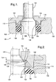
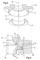
- the back up ring supports the o-ring axially to prevent extrusion of the o-ring through the seal assembly gland.
- the o-ring accommodates any radial clearances which can lead to extrusion of the o-ring.
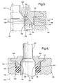
- the back up ring will collapse or crush during assembly to absorb that part of the component radial dimensional stack that would otherwise not meet radial clearances required to prevent extrusion of the o-ring.
- radial clearances can be met with higher component radial stack limits.
- the wedge design can be specified to the OD or ID of the o-ring depending upon where the larger radial clearance exists.
Landscapes
- Engineering & Computer Science (AREA)
- General Engineering & Computer Science (AREA)
- Physics & Mathematics (AREA)
- Mechanical Engineering (AREA)
- Electromagnetism (AREA)
- Fluid Mechanics (AREA)
- Transportation (AREA)
- Sealing Devices (AREA)
- Mechanical Sealing (AREA)
Claims (12)
- Anordnung, die in einem Bohrungsloch (108) eines Werkstücks (106) fixierbar ist und einen Durchbruch in der Oberfläche des Werkstücks durch eine einsetzbare Welle abdichtet, wobei die Anordnung aufweist:einen Flansch (104), der am Werkstück (106) mit einem Bohrungsloch (108) darin fixiert werden soll, wobei das Bohrungsloch (108) die Welle (102) entlang einer gemeinsamen Achse (138) aufnehmen kann, und wobei der Flansch (104) die Welle (102) umgibt;einen Stützring (122), der die Welle (102) umgibt; undeinen O-Ring (136), der die Welle (102) umgibt, so dass er mit der Welle (102), dem Stützring (122) und dem Bohrungsloch (108) in physischem Kontakt steht;dadurch gekennzeichnet,dass der Flansch (104), der die Welle (102) umgibt, aufweist:ein vorstehendes Element (110) mit einer ersten Oberfläche (112), die sich vom Flansch (104) parallel zur Achse (138) in das Bohrungsloch (108) erstreckt, und einer zweiten Oberfläche (116), die sich vom Flansch (104) in das Bohrungsloch (108) erstreckt, wodurch sie einen Winkel Alpha mit der ersten Oberfläche (112) bildet; undeine zur Achse senkrechte Aufsitzfläche (118) ;wobei das vorstehende Element (110) einen ringförmigen Raum (120) zwischen der Welle (102), der Aufsitzfläche (118) und der zweiten Oberfläche (116) des vorstehenden Elements (110) definiert;der die Welle (102) umgebende Stützring (122) innerhalb des ringförmigen Raums (120) angeordnet ist und eine zur Aufsitzfläche (118) parallele dritte Oberfläche (124), eine gegenüberliegende konkave vierte Oberfläche (126) mit einer von der dritten Oberfläche (124) weg gerichteten Krümmung, eine zur ersten Oberfläche (112) parallele fünfte Oberfläche (130) und eine gewinkelte sechste Oberfläche (140) aufweist, die zur zweiten Oberfläche (116) parallel ist und mit ihr verschiebbar in Kontakt steht;wobei in einem zusammengebauten Zustand ein erster variabler Zwischenraum (128) zwischen der fünften Oberfläche (130) des Stützrings (112) und einer Außenfläche der Welle definiert wird und ein zweiter variabler Zwischenraum (134) zwischen der dritten Oberfläche (124) des Stützrings (122) und der Aufsitzfläche (118) des Flansches (104) definiert wird;undder die Welle (102) umgebende O-Ring (136) innerhalb der Krümmung der konkaven Oberfläche (126) angeordnet ist;wobei der Stützring (122), wenn er axialen Kräften (148) ausgesetzt ist, sich entlang der Achse (138) bewegt und entlang der zweiten Oberfläche (116) des vorstehenden Elements (110) gleitet, um im ringförmigen Raum (120) einen Keil zu bilden, wodurch der erste und zweite variable Zwischenraum (128, 134) minimiert werden.
- Anordnung nach Anspruch 1,
wobei der Stützring (122) Nylon aufweist. - Anordnung nach Anspruch 1,
wobei der O-Ring (136) ein Elastomer aufweist. - Anordnung nach Anspruch 1,
wobei das vorstehende Element (110) ein geformtes Element mit dreieckigem Querschnitt ist. - Anordnung nach Anspruch 1,
wobei in einem zusammengebauten Zustand die erste Oberfläche (112) des vorstehenden Elements (110) mit einer Oberfläche (114) des Bohrungslochs (108) in Kontakt steht. - Anordnung nach Anspruch 1,
wobei in einem zusammengebauten Zustand die erste Oberfläche (112) des vorstehenden Elements (110) mit einer Außenfläche der Welle (102) in Kontakt steht. - Anordnung, die in einem Bohrungsloch (108) eines Werkstücks (106) fixierbar ist und einen Durchbruch in der Oberfläche des Werkstücks durch eine einsetzbare Welle abdichtet, wobei die Anordnung aufweist:einen Flansch (104), der am Werkstück (106) mit einem Bohrungsloch (108) darin fixiert werden soll, wobei das Bohrungsloch (108) die Welle (102) entlang einer gemeinsamen Achse (138) aufnehmen kann, wobei der Flansch (104) die Welle (102) umgibt;einen Stützring (122), der die Welle (102) umgibt; undeinen O-Ring (136), der die Welle (102) umgibt, so dass er mit der Welle (102), dem Stützring (122) und dem Bohrungsloch (108) in physischem Kontakt steht;dadurch gekennzeichnet,dass der Flansch (104), der die Welle (102) umgibt, aufweist:ein vorstehendes Element (110) mit einer ersten Oberfläche (112), die sich vom Flansch (104) parallel zur Achse (138) in das Bohrungsloch (108) erstreckt, und einer zweiten Oberfläche (116), die sich vom Flansch (104) in das Bohrungsloch (108) erstreckt, wodurch sie einen Winkel Alpha mit der ersten Oberfläche (112) bildet; undeine zur Achse senkrechte Aufsitzfläche (118) ;wobei das vorstehende Element (110) einen ringförmigen Raum (120) zwischen dem Bohrungsloch (108), der Aufsitzfläche (118) und der zweiten Oberfläche (116) des vorstehenden Elements (110) definiert;der die Welle (102) umgebende Stützring (122) innerhalb des ringförmigen Raums (120) angeordnet ist und eine zur Aufsitzfläche (118) parallele dritte Oberfläche (124), eine gegenüberliegende konkave vierte Oberfläche (126) mit einer von der dritten Oberfläche (124) weg gerichteten Krümmung, eine zur ersten Oberfläche (112) parallele fünfte Oberfläche (130) und eine gewinkelte sechste Oberfläche (140) aufweist, die zur zweiten Oberfläche (116) parallel ist und mit ihr verschiebbar in Kontakt steht;wobei in einem zusammengebauten Zustand ein erster variabler Zwischenraum (128) zwischen der fünften Oberfläche (130) des Stützrings (112) und einer Außenfläche des Stützrings (122) und der Oberfläche des Bohrungslochs (108) definiert wird und ein zweiter variabler Zwischenraum (134) zwischen der dritten Oberfläche (124) des Stützrings (122) und der Aufsitzfläche (118) des Flansches (104) definiert wird;undder die Welle (102) umgebende O-Ring (136) innerhalb der Krümmung der konkaven Oberfläche (126) angeordnet ist;wobei der Stützring (122), wenn er axialen Kräften (148) ausgesetzt ist, sich entlang der Achse (138) bewegt und entlang der zweiten Oberfläche (116) des vorstehenden Elements (110) gleitet, um im ringförmigen Raum (120) einen Keil zu bilden, wodurch der erste und zweite variable Zwischenraum (128, 134) minimiert werden.
- Anordnung nach Anspruch 7,
wobei der Stützring (122) Nylon aufweist. - Anordnung nach Anspruch 7,
wobei der O-Ring (136) ein Elastomer aufweist. - Anordnung nach Anspruch 7,
wobei das vorstehende Element (110) ein geformtes Element mit dreieckigem Querschnitt ist. - Anordnung nach Anspruch 7,
wobei in einem zusammengebauten Zustand die erste Oberfläche (112) des vorstehenden Elements (110) mit einer Oberfläche (114) des Bohrungslochs (108) in Kontakt steht. - Anordnung nach Anspruch 7,
wobei in einem zusammengebauten Zustand die erste Oberfläche (112) des vorstehenden Elements (110) mit einer Außenfläche der Welle (102) in Kontakt steht.
Applications Claiming Priority (2)
| Application Number | Priority Date | Filing Date | Title |
|---|---|---|---|
| US339951 | 2003-01-10 | ||
| US10/339,951 US6758478B1 (en) | 2003-01-10 | 2003-01-10 | Elastomeric seal anti-extrusion wedge backup ring and flange |
Publications (3)
| Publication Number | Publication Date |
|---|---|
| EP1437536A2 EP1437536A2 (de) | 2004-07-14 |
| EP1437536A3 EP1437536A3 (de) | 2004-08-04 |
| EP1437536B1 true EP1437536B1 (de) | 2006-07-19 |
Family
ID=32507473
Family Applications (1)
| Application Number | Title | Priority Date | Filing Date |
|---|---|---|---|
| EP03078889A Expired - Lifetime EP1437536B1 (de) | 2003-01-10 | 2003-12-08 | Spielfreier Stützring für Elastomerdichtung und Flansch |
Country Status (3)
| Country | Link |
|---|---|
| US (1) | US6758478B1 (de) |
| EP (1) | EP1437536B1 (de) |
| DE (1) | DE60306883T2 (de) |
Families Citing this family (24)
| Publication number | Priority date | Publication date | Assignee | Title |
|---|---|---|---|---|
| EP1718890B1 (de) * | 2004-02-25 | 2015-09-16 | BUCKNELL, John Wentworth | Dichtungen für hydraulische anordnungen |
| US7341258B2 (en) * | 2004-09-24 | 2008-03-11 | Greene, Tweed Of Delaware, Inc. | Cammed seal assembly with sealing ring having an angled leg portion and foot portion with elastomeric energizer element |
| DE102004050584B4 (de) | 2004-10-15 | 2006-09-14 | Gapi Technische Produkte Gmbh | Dichtungsanordnung mit Dichtring und Stützring |
| US20060232019A1 (en) * | 2005-04-19 | 2006-10-19 | Garrison Hubert F | Encapsulated back-up system for use with seal system |
| US7677531B1 (en) * | 2006-02-02 | 2010-03-16 | Anthony Scott Hollars | Non-axial actuable valve capable of retaining both high and low pressures |
| US20070222162A1 (en) * | 2006-03-24 | 2007-09-27 | Stoner Jack C | Back-up ring and sealing assembly |
| US7828301B2 (en) | 2008-01-25 | 2010-11-09 | Intelliserv, Llc | Self-energized backup ring for annular seals |
| US20090315266A1 (en) * | 2008-06-19 | 2009-12-24 | Baker Hughes Incorporated | Extrusion-Resistant Nose Seal |
| US20120038115A1 (en) * | 2009-02-12 | 2012-02-16 | Halliburton Energy Services, Inc. | Anti-Extrusion Seal for High Temperature Applications |
| CN103370543A (zh) | 2010-12-16 | 2013-10-23 | S.P.M.流量控制股份有限公司 | 具有包括挤压凹部的楔状密封的活塞填密件 |
| DE202011104825U1 (de) | 2011-08-20 | 2011-11-23 | Gapi Technische Produkte Gmbh | Dichtungsanordnung |
| JP5458076B2 (ja) * | 2011-09-20 | 2014-04-02 | 本田技研工業株式会社 | 封止構造体 |
| US9995394B2 (en) | 2012-01-18 | 2018-06-12 | Halliburton Energy Services, Inc. | Seal ring backup devices and methods for preventing extrusion |
| DE102012001004A1 (de) * | 2012-01-20 | 2013-07-25 | Uhde High Pressure Technologies Gmbh | Stützringanordnung für eine Hochdruckdichtung |
| US9022121B1 (en) | 2012-06-22 | 2015-05-05 | Wellbore Specialties, Llc | Back-up ring for a liner top test tool |
| US20170211703A1 (en) * | 2014-05-29 | 2017-07-27 | Nok Corporation | Sealing structure and sealing device |
| RU2659935C1 (ru) | 2014-12-30 | 2018-07-04 | Халлибертон Энерджи Сервисез, Инк. | Предварительно напряженное опорное кольцо многократного использования |
| US11448210B2 (en) | 2015-07-02 | 2022-09-20 | Spm Oil & Gas Inc. | Valve for reciprocating pump assembly |
| US10221848B2 (en) | 2015-07-02 | 2019-03-05 | S.P.M. Flow Control, Inc. | Valve for reciprocating pump assembly |
| US10634255B2 (en) * | 2016-12-21 | 2020-04-28 | Baker Hughes, A Ge Company, Llc | Pressure activated anti-extrusion ring for annular seal, seal configuration, and method |
| US20200096111A1 (en) * | 2018-09-25 | 2020-03-26 | Baker Hughes, A Ge Company, Llc | Anti-Extrusion Device for Pressure Unloading Applications |
| JP7243978B2 (ja) * | 2019-01-23 | 2023-03-22 | 株式会社荒井製作所 | 密封装置 |
| US11519537B2 (en) | 2020-11-16 | 2022-12-06 | Saudi Arabian Oil Company | Self-sealing a flange |
| US12540617B1 (en) * | 2024-03-19 | 2026-02-03 | Hydrablast Technologies, Inc. | Multi-component plunger seal system for a pump and method |
Family Cites Families (41)
| Publication number | Priority date | Publication date | Assignee | Title |
|---|---|---|---|---|
| US1331216A (en) * | 1919-03-31 | 1920-02-17 | Schneider & Cie | Hydraulic-joint packing |
| US1710203A (en) * | 1928-02-27 | 1929-04-23 | William H Burstall | Packer |
| US2513533A (en) * | 1945-12-03 | 1950-07-04 | Levitation Ltd | Packing device for fluid pressure apparatus |
| US2494598A (en) * | 1947-06-16 | 1950-01-17 | Alfred C Waring | Hydraulic packing and seal |
| US2456356A (en) * | 1947-12-09 | 1948-12-14 | Joseph S Aber | Packing gasket and static seal |
| US2616731A (en) * | 1948-06-24 | 1952-11-04 | Dean W Osmun | Packing unit |
| US2705177A (en) * | 1950-12-19 | 1955-03-29 | Alfred C Waring | Hydraulic packing and seal especially adapted to reciprocating parts |
| US2739855A (en) * | 1951-12-21 | 1956-03-27 | Earl F Bruning | Composite packing |
| US3097855A (en) * | 1959-06-26 | 1963-07-16 | George H Allen | Sealing arrangement |
| US3132869A (en) * | 1961-03-13 | 1964-05-12 | Malcolm R Maben | Fluid pressure responsive seal assembly |
| US3323806A (en) * | 1962-12-14 | 1967-06-06 | H W Loud Machine Works Inc | Fluid seal |
| US3269737A (en) * | 1963-11-12 | 1966-08-30 | Cessna Aircraft Co | Unbalanced pressure shaft seal |
| US3584884A (en) * | 1968-09-10 | 1971-06-15 | Western Electric Co | Pressure elongatable support apparatus |
| US3606356A (en) * | 1968-11-19 | 1971-09-20 | Western Electric Co | High-pressure seal assembly |
| GB1297161A (de) * | 1969-01-10 | 1972-11-22 | ||
| US3765690A (en) * | 1971-01-21 | 1973-10-16 | Ato Inc | Composite seal |
| US3774978A (en) | 1972-04-24 | 1973-11-27 | Minnesota Automotive Inc | Auxiliary hydraulic brake lock |
| SE419891B (sv) * | 1973-06-06 | 1981-08-31 | Asea Ab | Hogtryckstetning |
| FR2286990A1 (fr) * | 1974-10-04 | 1976-04-30 | Anvar | Dispositif d'etancheite |
| GB1564906A (en) * | 1976-11-02 | 1980-04-16 | Redland Pipes Ltd | Reactive pipe joint |
| USRE31171E (en) * | 1978-05-26 | 1983-03-08 | Textron, Inc. | Hydraulic piston rod seal |
| US4192519A (en) * | 1978-07-24 | 1980-03-11 | Buggele Alvin E | High pressure multi-purpose seal |
| US4352498A (en) | 1979-07-02 | 1982-10-05 | Greene, Tweed & Co., Inc. | Spring seal |
| FR2580764B1 (fr) * | 1985-04-22 | 1987-07-10 | Bertin & Cie | Dispositif d'etancheite haute pression entre deux elements en mouvement relatif |
| JPH0686167B2 (ja) | 1986-03-12 | 1994-11-02 | 日本電装株式会社 | 車輪支持構造 |
| US4802696A (en) | 1986-10-23 | 1989-02-07 | The Gates Rubber Company | Quick connect coupling |
| JPH0721316B2 (ja) | 1986-12-09 | 1995-03-08 | 本田技研工業株式会社 | 油圧式伝動装置 |
| US5086867A (en) | 1988-07-08 | 1992-02-11 | Tochigifujisangyo Kabushiki Kaisha | Power transmission apparatus |
| US4893878A (en) | 1988-09-27 | 1990-01-16 | Hilite Industries, Inc. | Inline proportioning valve for brake systems |
| JPH05296140A (ja) | 1992-04-15 | 1993-11-09 | Giichi Kuze | ゴム・シール直状管とゴム・シール・バッグ 構成のサーモ・アクチュエータ |
| JP2569208Y2 (ja) | 1992-10-13 | 1998-04-22 | 株式会社ユニシアジェックス | 電磁弁構造 |
| US5354103A (en) | 1994-01-28 | 1994-10-11 | Eaton Corporation | Quick connect conduit coupling |
| US6206432B1 (en) | 1998-01-26 | 2001-03-27 | Nok Corporation | Ball-lock-type quick-acting connector |
| US6173965B1 (en) * | 1998-12-28 | 2001-01-16 | Leopold J. Niessen | Actuator seal bearing assembly and method |
| US6173968B1 (en) * | 1999-04-27 | 2001-01-16 | Trw Inc. | Sealing ring assembly |
| US6312020B1 (en) | 1999-08-10 | 2001-11-06 | Ti Group Automotive Systems Corp | Connector for connecting a hose to a fluid path within a bore |
| US6189716B1 (en) | 1999-12-15 | 2001-02-20 | Delphi Technologies, Inc. | Secondary sealing of a fuel tank |
| US6490964B2 (en) | 2000-01-24 | 2002-12-10 | Delphi Technologies, Inc. | Master brake cylinders having overmolded seals |
| US6454240B1 (en) * | 2001-01-31 | 2002-09-24 | Delphi Technologies, Inc. | Anti-extrusion ring for use in conjunction with a vehicle solenoid valve |
| US6543746B2 (en) | 2001-02-21 | 2003-04-08 | Delphi Technologies, Inc. | Shaft leakage containment system for a gas control valve |
| US6588317B2 (en) | 2001-11-09 | 2003-07-08 | Delphi Technologies, Inc. | Power booster sealing mechanism |
-
2003
- 2003-01-10 US US10/339,951 patent/US6758478B1/en not_active Expired - Fee Related
- 2003-12-08 EP EP03078889A patent/EP1437536B1/de not_active Expired - Lifetime
- 2003-12-08 DE DE60306883T patent/DE60306883T2/de not_active Expired - Fee Related
Also Published As
| Publication number | Publication date |
|---|---|
| US6758478B1 (en) | 2004-07-06 |
| US20040135319A1 (en) | 2004-07-15 |
| EP1437536A3 (de) | 2004-08-04 |
| DE60306883D1 (de) | 2006-08-31 |
| EP1437536A2 (de) | 2004-07-14 |
| DE60306883T2 (de) | 2007-08-30 |
Similar Documents
| Publication | Publication Date | Title |
|---|---|---|
| EP1437536B1 (de) | Spielfreier Stützring für Elastomerdichtung und Flansch | |
| US5139274A (en) | Seal for a hydraulic ram | |
| US4787642A (en) | X-shaped high pressure sealing structure | |
| US11333248B2 (en) | Positive/negative pressure gasket | |
| EP0385635A2 (de) | Dichtungen | |
| WO2013138144A1 (en) | One-way pressure activated piston seal | |
| EP2166257A1 (de) | Fallkerb-Stützringe | |
| US20190093771A1 (en) | Pressure-activatable rotary seal and rotary seal assembly | |
| US3810639A (en) | Frangible backup ring for sealing rings | |
| US6648337B1 (en) | Backup ring with controlled spacing | |
| US5725221A (en) | Two piece seal | |
| EP2594829A1 (de) | Druckentlastete radiale Drehwellendichtung | |
| EP0410074B1 (de) | Anlage zum Verringern von Radialbelastung und diese umfassende Gleitlager und Schraubenverdichter | |
| EP1950472B1 (de) | Dichtungsvorrichtung | |
| CA2948211C (en) | Rotary joint for a high pressure fluid | |
| WO2009114527A1 (en) | Pressure regulating seal | |
| EP1433971B1 (de) | Hydraulisches System | |
| US5330201A (en) | Sealing assembly | |
| KR100594821B1 (ko) | 볼 밸브용 환상형 씰 | |
| WO2001040685A1 (en) | Snap-in retainer for a fluid seal | |
| EP1950473B1 (de) | Eingeschlossene vorrichtung zur kohlendioxidgasversiegelung | |
| EP0998643B1 (de) | Schraubenloser rohrverbinder | |
| CA2401202A1 (en) | Sealing system | |
| EP3726098B1 (de) | Schmiersystem für einen kugelrollspindelaktuator | |
| RU2129681C1 (ru) | Уплотнительное соединение |
Legal Events
| Date | Code | Title | Description |
|---|---|---|---|
| PUAI | Public reference made under article 153(3) epc to a published international application that has entered the european phase |
Free format text: ORIGINAL CODE: 0009012 |
|
| PUAL | Search report despatched |
Free format text: ORIGINAL CODE: 0009013 |
|
| AK | Designated contracting states |
Kind code of ref document: A2 Designated state(s): AT BE BG CH CY CZ DE DK EE ES FI FR GB GR HU IE IT LI LU MC NL PT RO SE SI SK TR |
|
| AX | Request for extension of the european patent |
Extension state: AL LT LV MK |
|
| AK | Designated contracting states |
Kind code of ref document: A3 Designated state(s): AT BE BG CH CY CZ DE DK EE ES FI FR GB GR HU IE IT LI LU MC NL PT RO SE SI SK TR |
|
| AX | Request for extension of the european patent |
Extension state: AL LT LV MK |
|
| 17P | Request for examination filed |
Effective date: 20050204 |
|
| AKX | Designation fees paid |
Designated state(s): DE FR GB |
|
| 17Q | First examination report despatched |
Effective date: 20050506 |
|
| RBV | Designated contracting states (corrected) |
Designated state(s): DE FR GB |
|
| GRAP | Despatch of communication of intention to grant a patent |
Free format text: ORIGINAL CODE: EPIDOSNIGR1 |
|
| GRAS | Grant fee paid |
Free format text: ORIGINAL CODE: EPIDOSNIGR3 |
|
| GRAA | (expected) grant |
Free format text: ORIGINAL CODE: 0009210 |
|
| AK | Designated contracting states |
Kind code of ref document: B1 Designated state(s): DE FR GB |
|
| REG | Reference to a national code |
Ref country code: GB Ref legal event code: FG4D |
|
| REF | Corresponds to: |
Ref document number: 60306883 Country of ref document: DE Date of ref document: 20060831 Kind code of ref document: P |
|
| ET | Fr: translation filed | ||
| PLBE | No opposition filed within time limit |
Free format text: ORIGINAL CODE: 0009261 |
|
| STAA | Information on the status of an ep patent application or granted ep patent |
Free format text: STATUS: NO OPPOSITION FILED WITHIN TIME LIMIT |
|
| 26N | No opposition filed |
Effective date: 20070420 |
|
| PGFP | Annual fee paid to national office [announced via postgrant information from national office to epo] |
Ref country code: FR Payment date: 20071210 Year of fee payment: 5 |
|
| PGFP | Annual fee paid to national office [announced via postgrant information from national office to epo] |
Ref country code: DE Payment date: 20071206 Year of fee payment: 5 |
|
| GBPC | Gb: european patent ceased through non-payment of renewal fee |
Effective date: 20071208 |
|
| PG25 | Lapsed in a contracting state [announced via postgrant information from national office to epo] |
Ref country code: GB Free format text: LAPSE BECAUSE OF NON-PAYMENT OF DUE FEES Effective date: 20071208 |
|
| REG | Reference to a national code |
Ref country code: FR Ref legal event code: ST Effective date: 20090831 |
|
| PG25 | Lapsed in a contracting state [announced via postgrant information from national office to epo] |
Ref country code: DE Free format text: LAPSE BECAUSE OF NON-PAYMENT OF DUE FEES Effective date: 20090701 |
|
| PG25 | Lapsed in a contracting state [announced via postgrant information from national office to epo] |
Ref country code: FR Free format text: LAPSE BECAUSE OF NON-PAYMENT OF DUE FEES Effective date: 20081231 |