EP1437580A2 - Liquid level measurement using a float attached to a rotating arm - Google Patents
Liquid level measurement using a float attached to a rotating arm Download PDFInfo
- Publication number
- EP1437580A2 EP1437580A2 EP20030030022 EP03030022A EP1437580A2 EP 1437580 A2 EP1437580 A2 EP 1437580A2 EP 20030030022 EP20030030022 EP 20030030022 EP 03030022 A EP03030022 A EP 03030022A EP 1437580 A2 EP1437580 A2 EP 1437580A2
- Authority
- EP
- European Patent Office
- Prior art keywords
- fuel
- sensor
- float
- rotation
- tank
- Prior art date
- Legal status (The legal status is an assumption and is not a legal conclusion. Google has not performed a legal analysis and makes no representation as to the accuracy of the status listed.)
- Withdrawn
Links
- 239000007788 liquid Substances 0.000 title claims abstract description 28
- 238000005259 measurement Methods 0.000 title 1
- 238000006073 displacement reaction Methods 0.000 claims abstract description 19
- 230000008878 coupling Effects 0.000 claims description 12
- 238000010168 coupling process Methods 0.000 claims description 12
- 238000005859 coupling reaction Methods 0.000 claims description 12
- 238000001514 detection method Methods 0.000 claims description 11
- 239000000446 fuel Substances 0.000 description 63
- 239000002828 fuel tank Substances 0.000 description 36
- 230000002093 peripheral effect Effects 0.000 description 4
- 230000003321 amplification Effects 0.000 description 3
- 238000012937 correction Methods 0.000 description 3
- 239000000463 material Substances 0.000 description 3
- 238000003199 nucleic acid amplification method Methods 0.000 description 3
- 238000005192 partition Methods 0.000 description 3
- 238000012545 processing Methods 0.000 description 3
- 239000000470 constituent Substances 0.000 description 2
- 230000007797 corrosion Effects 0.000 description 2
- 238000005260 corrosion Methods 0.000 description 2
- 238000013461 design Methods 0.000 description 2
- 230000000694 effects Effects 0.000 description 2
- 230000007774 longterm Effects 0.000 description 2
- 239000007769 metal material Substances 0.000 description 2
- 229920005989 resin Polymers 0.000 description 2
- 239000011347 resin Substances 0.000 description 2
- 101100314150 Caenorhabditis elegans tank-1 gene Proteins 0.000 description 1
- 230000001133 acceleration Effects 0.000 description 1
- 238000013459 approach Methods 0.000 description 1
- 230000007423 decrease Effects 0.000 description 1
- 230000003247 decreasing effect Effects 0.000 description 1
- 238000010586 diagram Methods 0.000 description 1
- 238000002955 isolation Methods 0.000 description 1
- 238000004519 manufacturing process Methods 0.000 description 1
- 238000012986 modification Methods 0.000 description 1
- 230000004048 modification Effects 0.000 description 1
- 230000002265 prevention Effects 0.000 description 1
- 239000000758 substrate Substances 0.000 description 1
- 229920003002 synthetic resin Polymers 0.000 description 1
- 239000000057 synthetic resin Substances 0.000 description 1
Images


Classifications
-
- G—PHYSICS
- G01—MEASURING; TESTING
- G01F—MEASURING VOLUME, VOLUME FLOW, MASS FLOW OR LIQUID LEVEL; METERING BY VOLUME
- G01F23/00—Indicating or measuring liquid level or level of fluent solid material, e.g. indicating in terms of volume or indicating by means of an alarm
- G01F23/30—Indicating or measuring liquid level or level of fluent solid material, e.g. indicating in terms of volume or indicating by means of an alarm by floats
- G01F23/32—Indicating or measuring liquid level or level of fluent solid material, e.g. indicating in terms of volume or indicating by means of an alarm by floats using rotatable arms or other pivotable transmission elements
- G01F23/36—Indicating or measuring liquid level or level of fluent solid material, e.g. indicating in terms of volume or indicating by means of an alarm by floats using rotatable arms or other pivotable transmission elements using electrically actuated indicating means
Definitions
- the present invention relates to a system for detecting the level of liquid in a tank, which is suitably used, for example, in detecting the level of fuel accumulated or accommodated in an automotive fuel tank.
- the fuel tank mounted on the vehicle such as automobile is provided with a float-type level detecting system, for example, to detect the remaining amount of fuel accumulated in the tank.
- the float-type level detecting system comprises a float arranged vertically movably with the level of fuel accumulated in the fuel tank and a sensor part provided to the tank and for sensing a fuel level position in accordance with displacement of the float.
- the float is coupled to an arm which is rotatable with respect to the sensor part.
- the float is vertically displaced with the liquid level in the tank, rotating the arm by an angle corresponding to that displacement.
- the sensor part which is in the form of a potentiometer or the like, comprises a resistor exposedly fixedly arranged in the fuel tank and a conductive slide brush which moves on the resistor in a sliding way when the arm rotates.
- the sensor part senses a position of the float, i.e. a fuel level position, which is announced as fuel remaining amount to a driver and the like.
- the sensor part includes a potentiometer or the like to sense displacement of the float as displacement of a fuel level position.
- the resistor of the sensor part is exposedly disposed in the fuel tank for slide contact with the slide brush of the arm. And the resistor and the slide brush are often immersed in fuel in the fuel tank.
- the resistor and the slide brush can be subject to corrosion by various constituents and the like contained in fuel or cause contact failure, raising a problem of lowering the durability and reliability of the system.
- an object of the present invention to provide a system for detecting the level of liquid in a tank, which allows stable detection of a liquid level position in the tank over the long term without causing anomaly, and thus contributes to enhancement in the durability and reliability of the system.
- the present invention provides generally a system for detecting a level of liquid in a tank, which comprises: a float which produces a displacement with the liquid level; a sensor part provided to the tank, the sensor part sensing a position of the liquid level in accordance with the displacement of the float; and a casing arranged in the tank, the casing being isolated from the liquid, the casing accommodating the sensor part.
- FIG. 1 is a sectional view showing a first embodiment of a system for detecting the level of liquid in a tank according to the present invention
- FIG. 2 is a sectional view taken along the line II-II in FIG. 1;
- FIG. 3 is a fragmentary sectional view showing a sensor casing in FIG. 1;
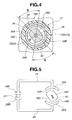
- FIG. 4 is an enlarged sectional view taken along the line IV-IV in FIG. 3;
- FIG. 5 is a diagram showing a magnetic circuit of a rotation-angle sensor
- FIG. 6 is a view similar to FIG. 2, showing a second embodiment of the present invention.
- FIG. 7 is a view similar to FIG. 3, showing a sensor casing in FIG. 6;
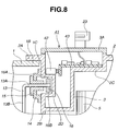
- FIG. 8 is a view similar to FIG. 3, showing a third embodiment of the present invention.
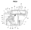
- FIG. 9 is a view similar to FIG. 8, showing a first variation of the present invention.
- FIG. 10 is a view similar to FIG. 9, showing a second variation of the present invention.
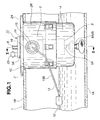
- a roughly box-shaped fuel tank 1 to be mounted on the vehicle such as automobile is formed as a container having a bottom face 1A, a top face 1B, and a peripheral wall, not shown, and for accumulating or accommodating fuel or liquid therein.
- Top face 1B of fuel tank 1 is formed with a mounting opening 1C to which a lid 2 as will be described later is attached.
- lid 2 is attached to mounting opening 1C of fuel tank 1, and comprises a closing plate 2A for concealing mounting opening 1C of tank 1, a cylindrical chamber mounting portion 2B protruding from closing plate 2A into tank 1 through mounting opening 1C, and an inner partition wall 2C arranged between closing plate 2A and chamber mounting portion 2B to form a sensor casing 3 as will be described later on the inner-periphery side of chamber mounting portion 2B.
- a bottomed cylindrical sensor mounting portion 2D is formed at chamber mounting portion 2B to protrude radially inward into sensor casing 3.
- the inner periphery of sensor mounting portion 2D opens as a bottomed concave to the outer periphery of chamber mounting portion 2B.
- Lid 2 is formed of a synthetic resin or the like so that the magnetic field of a magnet 16 as will be described later acts into sensor casing 3 through sensor mounting portion 2D.
- Sensor casing 3 is arranged in fuel tank 1 through the use of lid 2 to accommodate rotation-angle sensor 17 as will be described later hermetically isolatedly from fuel in tank 1.
- sensor casing 3 is formed as a closed container isolated from a space of fuel tank 1.
- Sensor casing 3 has a top side concealed with a lid plate 3A.
- a bottomed cylindrical chamber 4 is arranged in fuel tank 1, and has a top side mounted to chamber mounting portion 2B of lid 2. Chamber 4 serves to always accumulate part of fuel in tank 1 so as to ensure a predetermined amount of fuel on the intake side of a fuel pump 5 as will be described later even if an inconvenience occurs such as small remaining amount of fuel in tank1, level of fuel inclined, or the like.
- Fuel pump 5 is disposed in chamber 4, and has an inlet port 5A for introducing fuel in chamber 4 and an outlet port 5B for feeding introduced fuel to a supply pipe 6 as will be described later. Fuel pump 5 serves to supply fuel to an automotive engine and the like. A filter, not shown, and the like may be arranged in chamber 4 together with fuel pump 5.
- Roughly L-shaped supply pipe 6 is arranged to supply fuel in fuel tank 1 to the engine.
- Supply pipe 6 has a base end connected to outlet port 5B of fuel pump 5 and a front end protruding outward of fuel tank 1 through lid 2 and connected to the engine.
- a suction-pump pipe 7 is connected at the middle position of supply pipe 6 to supply a predetermined amount of fuel discharged from fuel pump 5 to a suction pump 8 as will be described later.
- Suction pump 8 is arranged in chamber 4, and includes a jet pump or the like. Suction pump 8 has an inlet port 8A which opens to the outside of chamber 4 and an outlet port 8B which opens to the inside of chamber 4. Suction pump 8 serves to suck fuel outside chamber 4 with the aid of part of fuel discharged from fuel pump 5 and discharge it into chamber 4 through outlet port 8B.
- a fuel remaining-amount detecting system 11 is arranged in fuel tank 1 to serve as a level detecting system.
- Fuel remaining-amount detecting system 11 comprises sensor casing 3, a float 12, an arm 13 as will be described later, magnet 16, and rotation-angle sensor 17.
- Float 12 is floatably supported by arm 13, and moves vertically with the level of fuel accumulated in fuel tank 1 to rotate arm 13 accordingly.
- Arm 13 is formed of an elongated rod or the like, and comprises a rotation shank 13A located at the base end, a lever 13B protruding from the front end of rotation shank 13A radially outward, and a float mounting portion 13C bent to the front end of lever 13B and mounted to float 12.
- an annular arm bracket 14 is mounted to chamber mounting portion 2B of lid 2 so as to close a space in sensor mounting portion 2D from the radial outside of chamber mounting portion 2B.
- a support cylinder 15 is engaged at the inner periphery of arm bracket 14.
- Rotation shank 13A of arm 13 has a base end disposed in sensor mounting portion 2D and rotatably supported by arm bracket 14 through support cylinder 15. With this, when float 12 moves vertically, arm 13 rotates about an axis O-O.
- Magnet 16 is mounted to rotation shank 13A of arm 13 in a rotation locked way. Referring to FIGS. 3 and 4, magnet 16 is located outside sensor casing 3 and accommodated in sensor mounting portion 2D of lid 2. Magnet 16 rotates together with arm 13 in accordance with displacement of float 1, the angle of rotation of which is sensed by rotation-angle sensor 17 as a level position of fuel in fuel tank 1.
- Magnet 16 is formed of a roughly disc-shaped magnet material or the like, and comprises at the outer periphery convex circular surfaces 16A, 16B located at both diametral ends and forming N and S poles, for example, and flat surfaces 16C located between convex circular surfaces 16A, 16B.
- Convex circular surfaces 16A, 16B spreads circularly, and has a predetermined angle or central angle with respect to axis O-O or center O of arm 13.
- Magnetic-detection type rotation-angle sensor or sensor part 17 is accommodated in sensor casing 3 of lid 2.
- rotation-angle sensor 17 comprises a housing 18, yokes 19, 20, a Hall element 21, a circuit board 22 as will be described later, and the like, which are hermetically accommodated in sensor casing 3 and isolated from fuel in fuel tank 1.
- Housing 18 is formed like a bottomed cylinder out of an insulating resin material or the like, and comprises a cylindrical portion 18A located in sensor casing 3 and mounted to the outer periphery of sensor mounting portion 2D of lid 2 and a bottom portion 18B arranged at an end of cylindrical portion 18A.
- Yoke 19 is arranged in housing 18 to form a magnetic path.
- Yoke 19 is formed of a magnetic metallic material or the like, and comprises a magnet facing portion 19A spreading circularly along cylindrical portion 18A of housing 18 and an extension 19B extending radially inward from magnet facing portion 19A to the center of bottom portion 18B of housing 18.
- Yoke 20 is also arranged in housing 18 to form a magnetic path.
- yoke 20 is formed of a magnetic metallic material or the like, and comprises a magnet facing portion 20A and an extension 20B.
- magnet facing portions 19A, 20A of yokes 19, 20 are disposed to face each other across magnet 16, each spreading circularly and having a predetermined central angle.
- Magnet facing portion 19A faces convex circular surface 16A of magnet 16 across sensor mounting portion 2D of lid 2, whereas magnet facing portion 20A faces convex circular surface 16B across sensor mounting portion 2D.
- Facing areas S of magnet facing portions 19A, 20A and convex circular surfaces 16A, 16B vary with the angle of rotation of magnet 16 (arm 13, to be more specific).
- yokes 19, 20 are disposed to have extensions 19B, 20B overlapping one another with a given clearance to form a closed magnetic path through which the magnetic field of magnet passes.
- Hall element 21 is arranged in housing 18 and disposed between extensions 19B, 20B of yokes 19, 20.
- the magnetic field passing through yokes 19, 20 varies with the angle of rotation of arm 13, i.e. facing areas S of magnet 16 and yokes 19, 20.
- Hall element 21 detects a variation in the magnetic field as that in the angle of rotation of arm 13, which is output as a signal to circuit board 22.
- Circuit board 22 is mounted to the inside of sensor caring 3 and connected to Hall element 21.
- Circuit board 22 provides signal processing such as amplification and correction to an output signal of Hall element 21, for example, to generate a detection signal corresponding to a level position of fuel in fuel tank 1, which is output to the outside from a connector 23 provided to lid plate 3A of sensor casing 3, for example.
- the fuel level When the fuel level is inclined due to acceleration/deceleration, cornering, or the like of the vehicle, and that fuel tank 1 is roughly full of fuel and the like, the fuel level can increase up to a level position corresponding to rotation-angle sensor 17 around chamber 4.
- components such as rotation-angle sensor 17 and circuit board 22 are hermetically accommodated in sensor casing 3 of lid 2, and are thus isolated from fuel, resulting in their sure prevention from contacting fuel.
- sensor casing 3 is provided to lid 2 so as to accommodate rotation-angle sensor 17 hermetically isolatedly from fuel in fuel tank 1.
- components constituting rotation-angle sensor 17, such as housing 18, yokes 19, 20, Hall element 21, and circuit board 22, can hermetically be accommodated in sensor casing 3, resulting in their sure isolation and protection from fuel in fuel tank 1.
- rotation-angle sensor 17, circuit board 22, and the like can be prevented from being subject to corrosion by various constituents and the like contained in fuel or causing operation failure, leading to stable detection of the remaining amount of fuel accumulated in fuel tank 1 over the long term.
- This allows extension of the life of fuel remaining-amount detecting system 11, leading to enhancement in durability and reliability thereof.
- magnet 16 is provided to float 12 through arm 13 so as to sense the angle of rotation of magnet 16 by magnetic-detection type rotation-angle sensor 17.
- magnet 16 is provided to float 12 through arm 13 so as to sense the angle of rotation of magnet 16 by magnetic-detection type rotation-angle sensor 17.
- rotation-angle sensor 17 can sense the angle of rotation of magnet 16 as a level position in fuel tank 1 based on a variation in the magnetic field and the like.
- displacement of float 12 can stably be sensed by rotation-angle sensor 17 in a non-contact way without need of arranging a seal or the like between rotation-angle sensor 17 and magnet 16, resulting in easy achievement of closed-type fuel remaining-amount detecting system 11.
- FIGS. 6 and 7 there is shown second embodiment of the present invention which is substantially the same as the first embodiment except that the sensor part includes a potentiometer, and a non-contact coupling is arranged between the sensor part and the float.
- lid 31 is mounted to mounting opening 1C of fuel tank 1.
- lid 31 is formed of a resin material or the like which allows passage of the magnetic field, and comprises a closing plate 31A, a chamber mounting portion 31B, an inner partition wall 31C, and the like.
- a sensor casing 32 is formed as a closed container.
- Sensor casing 32 is concealed with a lid plate 32A.
- Chamber mounting portion 31 B has no sensor mounting portion 2D in the first embodiment.
- a fuel remaining-amount detecting system 33 is arranged in fuel tank 1 to serve as a level detecting system.
- Fuel remaining-amount detecting system 33 comprises sensor casing 32, float 12, arm 13, a rotation-angle sensor 34, and a magnet coupling 37 as will be described later.
- Rotation-angle sensor or sensor part 34 is accommodated in sensor casing 32 of lid 31.
- rotation-angle sensor 34 is in the form of a potentiometer or the like, and comprises a housing 34A mounted to the inside of sensor casing 34, a rotation shaft 34B rotatably supported by housing 34A, a resistor 34C mounted to housing 34A through a substrate and the like, a conductive slide brush 34D mounted to the outer periphery of rotation shaft 34B through a holder and the like in a rotation locked way, and the like.
- Rotation shaft 34B is disposed coaxial with rotation shank 13A of arm 13.
- Resistor 34C is formed circularly about rotation shaft 34B, and has a circumferential part which slide brush 34D makes slide contact.
- rotation-angle sensor 34 senses the angle of rotation of rotation shaft 34B coupled to arm 13 through magnet coupling 37 as a variation in value of resistance of resistor 34, which is output as a signal to a circuit board 35 arranged in sensor casing 32.
- Circuit board 35 provides signal processing such as amplification and correction to an output signal of rotation-angle sensor 34, for example, to generate a detection signal corresponding to a level position or remaining amount of fuel in fuel tank 1, which is output to the outside from a connector 36 provided to lid plate 32A of sensor casing 32, for example.
- Magnet coupling or non-contact coupling 37 is arranged between float 12 (arm 13, to be more specific) and rotation-angle sensor 34 for coupling therebetween through sensor casing 32.
- Magnet coupling 37 is disposed outside sensor casing 32, and comprises an annular outer magnet 37A mounted at the outer periphery of the base end of rotation shank 13A of arm 13 in a rotation locked way and an annular inner magnet 37B mounted to the outer periphery of rotation shaft 34B of rotation-angle sensor 34 in a rotation locked way.
- Magnets 37A, 37B have N and S poles formed circumferentially alternately, for example, and facing each other across chamber mounting portion 31B of lid 31.
- magnets 37A, 37B rotate together with N and S poles coupled magnetically, transmitting rotational displacement of arm 13 to rotation shaft 34B of rotation-angle sensor 34.
- the second embodiment can produce substantially the same effect as that of the first embodiment.
- magnet coupling 37 is arranged between arm 13 of float 12 and rotation-angle sensor 34, so that even with arm 13 and rotation-angle sensor 34 intercepted by sensor casing 32, magnet coupling 37 allows sure coupling therebetween in a non-contact way, achieving in this state stable detection of the remaining amount of fuel in fuel tank 1.
- Rotation-angle sensor 34, circuit board 35, and the like can surely be protected from fuel in fuel tank 1 through the use of sensor casing 32, leading to easy achievement of closed-type fuel remaining-amount detecting system 33.
- rotation-angle sensor 34 may include a general-purpose potentiometer or the like, obtaining enhanced design flexibility of the device.
- FIG. 8 there is shown third embodiment of the present invention which substantially the same as the first embodiment except that the Hall element is directly mounted on the circuit board.
- Fuel remaining-amount detecting system 41 is arranged in fuel tank 1 to serve as a level detecting system.
- Fuel remaining-amount detecting system 41 comprises sensor casing 3, float 12, arm 13, magnet 16, and a Hall IC 42 as will be described later.
- Hall IC or sensor part 42 is arranged in sensor casing 3, and comprises an integrated circuit having a Hall element and its peripheral devices packaged, for example.
- Hall IC 42 is mounted on a circuit board 43 as will be described later.
- Hall IC 42 is disposed at the outer periphery of sensor mounting portion 2D of lid 2, and faces the N or S pole (convex circular surface 16A, for example) of magnet 16 across sensor mounting portion 2D.
- convex circular surface 16A of magnet 16 approaches or separates from Hall IC 42, so that the magnetic field passing through Hall IC 42 varies with the angle of rotation of arm 13.
- Hall IC 42 detects a variation in the magnetic field as angle of rotation of arm 13, which is output as a signal to circuit board 43.
- Circuit board 43 is mounted to the inside of sensor casing 3, and is bent like a letter L, for example. Circuit board 43 has a surface connected to Hall IC 42. Circuit board 43 provides signal processing such as amplification and correction to an output signal of Hall IC 42, for example, to generate a detection signal corresponding to a level position or remaining amount of fuel in fuel tank 1, which is output to the outside from connector 23.
- the third embodiment can produce substantially the same effect as that of the first embodiment.
- Hall IC 42 is mounted on circuit board 43, allowing simplified structure of the sensor part, resulting not only in a reduction in number of parts and thus manufacturing cost, but also in an enhancement in design flexibility of the device.
- Hall IC 42 is disposed at the outer periphery of sensor mounting portion 2D of lid 2, and is mounted on the surface of circuit board 43 bent like a letter L.
- an alternative structure can be adopted as shown in first variation in FIG. 9, wherein a Hall IC 42' is mounted on the underside of a flat circuit board 43'.
- a lid 2' comprises a closing plate 2A', a chamber mounting portion 2B', and an inner partition wall 2C' with sensor mounting portion 2D cancelled.
- Hall IC 42 is mounted on the underside of circuit board 43', and is disposed at the inner periphery of chamber mounting portion 2B' at the position corresponding to convex circular surface 16A of magnet 16, for example.
- the present invention is applied to an automotive fuel tank.
- the present invention can be applied to various tanks for accumulating liquid other than fuel.
Landscapes
- Physics & Mathematics (AREA)
- Fluid Mechanics (AREA)
- General Physics & Mathematics (AREA)
- Level Indicators Using A Float (AREA)
- Cooling, Air Intake And Gas Exhaust, And Fuel Tank Arrangements In Propulsion Units (AREA)
Abstract
Description
- The present invention relates to a system for detecting the level of liquid in a tank, which is suitably used, for example, in detecting the level of fuel accumulated or accommodated in an automotive fuel tank.
- Typically, as disclosed in JP-U 64-38534, the fuel tank mounted on the vehicle such as automobile is provided with a float-type level detecting system, for example, to detect the remaining amount of fuel accumulated in the tank. The float-type level detecting system comprises a float arranged vertically movably with the level of fuel accumulated in the fuel tank and a sensor part provided to the tank and for sensing a fuel level position in accordance with displacement of the float.
- The float is coupled to an arm which is rotatable with respect to the sensor part. When fuel accumulated in the fuel tank increases or decreases, the float is vertically displaced with the liquid level in the tank, rotating the arm by an angle corresponding to that displacement.
- The sensor part, which is in the form of a potentiometer or the like, comprises a resistor exposedly fixedly arranged in the fuel tank and a conductive slide brush which moves on the resistor in a sliding way when the arm rotates.
- When a slide-contact position between the resistor and the slide brush varies with the angle of rotation of the arm, a value of resistance of the resistor varies accordingly. In accordance with this variation, the sensor part senses a position of the float, i.e. a fuel level position, which is announced as fuel remaining amount to a driver and the like.
- With the typical level detecting system, the sensor part includes a potentiometer or the like to sense displacement of the float as displacement of a fuel level position.
- However, the resistor of the sensor part is exposedly disposed in the fuel tank for slide contact with the slide brush of the arm. And the resistor and the slide brush are often immersed in fuel in the fuel tank.
- As a result, with years of use of the level detecting system, the resistor and the slide brush can be subject to corrosion by various constituents and the like contained in fuel or cause contact failure, raising a problem of lowering the durability and reliability of the system.
- It is, therefore, an object of the present invention to provide a system for detecting the level of liquid in a tank, which allows stable detection of a liquid level position in the tank over the long term without causing anomaly, and thus contributes to enhancement in the durability and reliability of the system.
- The present invention provides generally a system for detecting a level of liquid in a tank, which comprises: a float which produces a displacement with the liquid level; a sensor part provided to the tank, the sensor part sensing a position of the liquid level in accordance with the displacement of the float; and a casing arranged in the tank, the casing being isolated from the liquid, the casing accommodating the sensor part.
- The other objects and features of the present invention will become apparent from the following description with reference to the accompanying drawings, wherein:
- FIG. 1 is a sectional view showing a first embodiment of a system for detecting the level of liquid in a tank according to the present invention;
- FIG. 2 is a sectional view taken along the line II-II in FIG. 1;
- FIG. 3 is a fragmentary sectional view showing a sensor casing in FIG. 1;
- FIG. 4 is an enlarged sectional view taken along the line IV-IV in FIG. 3;
- FIG. 5 is a diagram showing a magnetic circuit of a rotation-angle sensor;
- FIG. 6 is a view similar to FIG. 2, showing a second embodiment of the present invention;
- FIG. 7 is a view similar to FIG. 3, showing a sensor casing in FIG. 6;
- FIG. 8 is a view similar to FIG. 3, showing a third embodiment of the present invention;
- FIG. 9 is a view similar to FIG. 8, showing a first variation of the present invention; and
- FIG. 10 is a view similar to FIG. 9, showing a second variation of the present invention.
- Referring to the drawings wherein like reference numerals designate like parts throughout the views, a description is made about a system for detecting the level of liquid in a tank embodying the present invention. In the illustrative embodiments, the present invention is applied to a fuel remaining-amount detecting system for motor vehicles.
- Referring to FIGS. 1-5, there is shown first embodiment of the present invention. A roughly box-
shaped fuel tank 1 to be mounted on the vehicle such as automobile is formed as a container having abottom face 1A, atop face 1B, and a peripheral wall, not shown, and for accumulating or accommodating fuel or liquid therein.Top face 1B offuel tank 1 is formed with a mounting opening 1C to which alid 2 as will be described later is attached. - Referring to FIGS. 2 and 3,
lid 2 is attached to mounting opening 1C offuel tank 1, and comprises aclosing plate 2A for concealing mounting opening 1C oftank 1, a cylindricalchamber mounting portion 2B protruding fromclosing plate 2A intotank 1 through mounting opening 1C, and aninner partition wall 2C arranged betweenclosing plate 2A andchamber mounting portion 2B to form asensor casing 3 as will be described later on the inner-periphery side ofchamber mounting portion 2B. - A bottomed cylindrical
sensor mounting portion 2D is formed atchamber mounting portion 2B to protrude radially inward intosensor casing 3. The inner periphery ofsensor mounting portion 2D opens as a bottomed concave to the outer periphery ofchamber mounting portion 2B.Lid 2 is formed of a synthetic resin or the like so that the magnetic field of amagnet 16 as will be described later acts intosensor casing 3 throughsensor mounting portion 2D. -
Sensor casing 3 is arranged infuel tank 1 through the use oflid 2 to accommodate rotation-angle sensor 17 as will be described later hermetically isolatedly from fuel intank 1. Byclosing plate 2A,chamber mounting portion 2B, innerperipheral wall 2C, and the like oflid 2,sensor casing 3 is formed as a closed container isolated from a space offuel tank 1.Sensor casing 3 has a top side concealed with alid plate 3A. - A bottomed
cylindrical chamber 4 is arranged infuel tank 1, and has a top side mounted tochamber mounting portion 2B oflid 2.Chamber 4 serves to always accumulate part of fuel intank 1 so as to ensure a predetermined amount of fuel on the intake side of afuel pump 5 as will be described later even if an inconvenience occurs such as small remaining amount of fuel in tank1, level of fuel inclined, or the like. -
Fuel pump 5 is disposed inchamber 4, and has aninlet port 5A for introducing fuel inchamber 4 and anoutlet port 5B for feeding introduced fuel to asupply pipe 6 as will be described later.Fuel pump 5 serves to supply fuel to an automotive engine and the like. A filter, not shown, and the like may be arranged inchamber 4 together withfuel pump 5. - Roughly L-
shaped supply pipe 6 is arranged to supply fuel infuel tank 1 to the engine.Supply pipe 6 has a base end connected tooutlet port 5B offuel pump 5 and a front end protruding outward offuel tank 1 throughlid 2 and connected to the engine. A suction-pump pipe 7 is connected at the middle position ofsupply pipe 6 to supply a predetermined amount of fuel discharged fromfuel pump 5 to asuction pump 8 as will be described later. -
Suction pump 8 is arranged inchamber 4, and includes a jet pump or the like.Suction pump 8 has aninlet port 8A which opens to the outside ofchamber 4 and anoutlet port 8B which opens to the inside ofchamber 4.Suction pump 8 serves to suck fuel outsidechamber 4 with the aid of part of fuel discharged fromfuel pump 5 and discharge it intochamber 4 throughoutlet port 8B. - A fuel remaining-
amount detecting system 11 is arranged infuel tank 1 to serve as a level detecting system. Fuel remaining-amount detecting system 11 comprisessensor casing 3, afloat 12, anarm 13 as will be described later,magnet 16, and rotation-angle sensor 17. - Float 12 is floatably supported by
arm 13, and moves vertically with the level of fuel accumulated infuel tank 1 to rotatearm 13 accordingly. -
Arm 13 is formed of an elongated rod or the like, and comprises arotation shank 13A located at the base end, alever 13B protruding from the front end ofrotation shank 13A radially outward, and afloat mounting portion 13C bent to the front end oflever 13B and mounted tofloat 12. - Referring to FIG. 3, an
annular arm bracket 14 is mounted tochamber mounting portion 2B oflid 2 so as to close a space insensor mounting portion 2D from the radial outside ofchamber mounting portion 2B. Asupport cylinder 15 is engaged at the inner periphery ofarm bracket 14.Rotation shank 13A ofarm 13 has a base end disposed insensor mounting portion 2D and rotatably supported byarm bracket 14 throughsupport cylinder 15. With this, whenfloat 12 moves vertically,arm 13 rotates about an axis O-O. -
Magnet 16 is mounted torotation shank 13A ofarm 13 in a rotation locked way. Referring to FIGS. 3 and 4,magnet 16 is located outsidesensor casing 3 and accommodated insensor mounting portion 2D oflid 2.Magnet 16 rotates together witharm 13 in accordance with displacement offloat 1, the angle of rotation of which is sensed by rotation-angle sensor 17 as a level position of fuel infuel tank 1. -
Magnet 16 is formed of a roughly disc-shaped magnet material or the like, and comprises at the outer periphery convexcircular surfaces flat surfaces 16C located between convexcircular surfaces circular surfaces arm 13. - Magnetic-detection type rotation-angle sensor or
sensor part 17 is accommodated insensor casing 3 oflid 2. Referring to FIGS. 3 and 4, rotation-angle sensor 17 comprises ahousing 18, yokes 19, 20, aHall element 21, acircuit board 22 as will be described later, and the like, which are hermetically accommodated insensor casing 3 and isolated from fuel infuel tank 1. -
Housing 18 is formed like a bottomed cylinder out of an insulating resin material or the like, and comprises acylindrical portion 18A located insensor casing 3 and mounted to the outer periphery ofsensor mounting portion 2D oflid 2 and abottom portion 18B arranged at an end ofcylindrical portion 18A. -
Yoke 19 is arranged inhousing 18 to form a magnetic path.Yoke 19 is formed of a magnetic metallic material or the like, and comprises amagnet facing portion 19A spreading circularly alongcylindrical portion 18A ofhousing 18 and anextension 19B extending radially inward frommagnet facing portion 19A to the center ofbottom portion 18B ofhousing 18.Yoke 20 is also arranged inhousing 18 to form a magnetic path. In a way substantially similar toyoke 19,yoke 20 is formed of a magnetic metallic material or the like, and comprises amagnet facing portion 20A and anextension 20B. - Referring to FIGS. 4 and 5,
magnet facing portions yokes magnet 16, each spreading circularly and having a predetermined central angle.Magnet facing portion 19A faces convexcircular surface 16A ofmagnet 16 acrosssensor mounting portion 2D oflid 2, whereasmagnet facing portion 20A faces convexcircular surface 16B acrosssensor mounting portion 2D. - Facing areas S of
magnet facing portions circular surfaces arm 13, to be more specific). As shown in FIG. 3, yokes 19, 20 are disposed to haveextensions - Referring to FIG. 5,
Hall element 21 is arranged inhousing 18 and disposed betweenextensions yokes arm 13 rotates, the magnetic field passing throughyokes arm 13, i.e. facing areas S ofmagnet 16 andyokes Hall element 21 detects a variation in the magnetic field as that in the angle of rotation ofarm 13, which is output as a signal tocircuit board 22. -
Circuit board 22 is mounted to the inside of sensor caring 3 and connected toHall element 21.Circuit board 22 provides signal processing such as amplification and correction to an output signal ofHall element 21, for example, to generate a detection signal corresponding to a level position of fuel infuel tank 1, which is output to the outside from aconnector 23 provided tolid plate 3A ofsensor casing 3, for example. - Next, operation of fuel remaining-
amount detecting system 11 is described. When a level position of fuel accumulated infuel tank 1 varies by refilling, consumption, and the like, float 12 is displaced with the level position, andarm 13 rotates in conjunction therewith. Then, the angle of rotation is detected by rotation-angle sensor 17,circuit board 22, and the like, which is output fromconnector 23 as a detection signal corresponding to the remaining amount of fuel infuel tank 1. Thus, the fuel remaining amount can be announced to a driver and the like. - When the fuel level is inclined due to acceleration/deceleration, cornering, or the like of the vehicle, and that
fuel tank 1 is roughly full of fuel and the like, the fuel level can increase up to a level position corresponding to rotation-angle sensor 17 aroundchamber 4. - However, components such as rotation-
angle sensor 17 andcircuit board 22 are hermetically accommodated insensor casing 3 oflid 2, and are thus isolated from fuel, resulting in their sure prevention from contacting fuel. - Then, in the first embodiment,
sensor casing 3 is provided tolid 2 so as to accommodate rotation-angle sensor 17 hermetically isolatedly from fuel infuel tank 1. Thus, components constituting rotation-angle sensor 17, such ashousing 18, yokes 19, 20,Hall element 21, andcircuit board 22, can hermetically be accommodated insensor casing 3, resulting in their sure isolation and protection from fuel infuel tank 1. - With this, rotation-
angle sensor 17,circuit board 22, and the like can be prevented from being subject to corrosion by various constituents and the like contained in fuel or causing operation failure, leading to stable detection of the remaining amount of fuel accumulated infuel tank 1 over the long term. This allows extension of the life of fuel remaining-amount detecting system 11, leading to enhancement in durability and reliability thereof. - In the first embodiment,
magnet 16 is provided to float 12 througharm 13 so as to sense the angle of rotation ofmagnet 16 by magnetic-detection type rotation-angle sensor 17. Thus, whenfloat 12 is displaced with the level of fuel infuel tank 1, smooth rotation ofmagnet 16 can be obtained in accordance with this displacement by virtue ofarm 13. - And even with
arm 13 and rotation-angle sensor 17 intercepted bysensor casing 3, rotation-angle sensor 17 can sense the angle of rotation ofmagnet 16 as a level position infuel tank 1 based on a variation in the magnetic field and the like. - Therefore, displacement of
float 12 can stably be sensed by rotation-angle sensor 17 in a non-contact way without need of arranging a seal or the like between rotation-angle sensor 17 andmagnet 16, resulting in easy achievement of closed-type fuel remaining-amount detecting system 11. - Referring to FIGS. 6 and 7, there is shown second embodiment of the present invention which is substantially the same as the first embodiment except that the sensor part includes a potentiometer, and a non-contact coupling is arranged between the sensor part and the float.
- Specifically, a
lid 31 is mounted to mountingopening 1C offuel tank 1. In the substantially same way aslid 2 in the first embodiment,lid 31 is formed of a resin material or the like which allows passage of the magnetic field, and comprises aclosing plate 31A, achamber mounting portion 31B, aninner partition wall 31C, and the like. - By closing
plate 31A,chamber mounting portion 31B, innerperipheral wall 31C, and the like oflid 31, asensor casing 32 is formed as a closed container.Sensor casing 32 is concealed with alid plate 32A.Chamber mounting portion 31 B has nosensor mounting portion 2D in the first embodiment. - A fuel remaining-
amount detecting system 33 is arranged infuel tank 1 to serve as a level detecting system. Fuel remaining-amount detecting system 33 comprisessensor casing 32,float 12,arm 13, a rotation-angle sensor 34, and amagnet coupling 37 as will be described later. - Rotation-angle sensor or
sensor part 34 is accommodated insensor casing 32 oflid 31. Referring to FIG. 7, rotation-angle sensor 34 is in the form of a potentiometer or the like, and comprises ahousing 34A mounted to the inside ofsensor casing 34, arotation shaft 34B rotatably supported byhousing 34A, aresistor 34C mounted tohousing 34A through a substrate and the like, aconductive slide brush 34D mounted to the outer periphery ofrotation shaft 34B through a holder and the like in a rotation locked way, and the like. -
Rotation shaft 34B is disposed coaxial withrotation shank 13A ofarm 13.Resistor 34C is formed circularly aboutrotation shaft 34B, and has a circumferential part which slidebrush 34D makes slide contact. - When
rotation shaft 34B rotates, slidebrush 34D moves onresistor 34C in a sliding way in accordance with the angle of rotation ofrotation shaft 34B, increasing or decreasing a value of resistance ofresistor 34. With this, rotation-angle sensor 34 senses the angle of rotation ofrotation shaft 34B coupled toarm 13 throughmagnet coupling 37 as a variation in value of resistance ofresistor 34, which is output as a signal to acircuit board 35 arranged insensor casing 32. -
Circuit board 35 provides signal processing such as amplification and correction to an output signal of rotation-angle sensor 34, for example, to generate a detection signal corresponding to a level position or remaining amount of fuel infuel tank 1, which is output to the outside from aconnector 36 provided tolid plate 32A ofsensor casing 32, for example. - Magnet coupling or
non-contact coupling 37 is arranged between float 12 (arm 13, to be more specific) and rotation-angle sensor 34 for coupling therebetween throughsensor casing 32. -
Magnet coupling 37 is disposed outsidesensor casing 32, and comprises an annularouter magnet 37A mounted at the outer periphery of the base end ofrotation shank 13A ofarm 13 in a rotation locked way and an annularinner magnet 37B mounted to the outer periphery ofrotation shaft 34B of rotation-angle sensor 34 in a rotation locked way. -
Magnets chamber mounting portion 31B oflid 31. Whenarm 13 rotates,magnets arm 13 torotation shaft 34B of rotation-angle sensor 34. - Then, the second embodiment can produce substantially the same effect as that of the first embodiment. In the second embodiment, particularly,
magnet coupling 37 is arranged betweenarm 13 offloat 12 and rotation-angle sensor 34, so that even witharm 13 and rotation-angle sensor 34 intercepted bysensor casing 32,magnet coupling 37 allows sure coupling therebetween in a non-contact way, achieving in this state stable detection of the remaining amount of fuel infuel tank 1. - Rotation-
angle sensor 34,circuit board 35, and the like can surely be protected from fuel infuel tank 1 through the use ofsensor casing 32, leading to easy achievement of closed-type fuel remaining-amount detecting system 33. In place of the magnetic-detection type, rotation-angle sensor 34 may include a general-purpose potentiometer or the like, obtaining enhanced design flexibility of the device. - Referring to FIG. 8, there is shown third embodiment of the present invention which substantially the same as the first embodiment except that the Hall element is directly mounted on the circuit board.
- Specifically, a fuel remaining-
amount detecting system 41 is arranged infuel tank 1 to serve as a level detecting system. Fuel remaining-amount detecting system 41 comprisessensor casing 3, float 12,arm 13,magnet 16, and aHall IC 42 as will be described later. - Hall IC or
sensor part 42 is arranged insensor casing 3, and comprises an integrated circuit having a Hall element and its peripheral devices packaged, for example.Hall IC 42 is mounted on acircuit board 43 as will be described later.Hall IC 42 is disposed at the outer periphery ofsensor mounting portion 2D oflid 2, and faces the N or S pole (convexcircular surface 16A, for example) ofmagnet 16 acrosssensor mounting portion 2D. - When
arm 13 rotates, convexcircular surface 16A ofmagnet 16, for example, approaches or separates fromHall IC 42, so that the magnetic field passing throughHall IC 42 varies with the angle of rotation ofarm 13. With this,Hall IC 42 detects a variation in the magnetic field as angle of rotation ofarm 13, which is output as a signal tocircuit board 43. -
Circuit board 43 is mounted to the inside ofsensor casing 3, and is bent like a letter L, for example.Circuit board 43 has a surface connected toHall IC 42.Circuit board 43 provides signal processing such as amplification and correction to an output signal ofHall IC 42, for example, to generate a detection signal corresponding to a level position or remaining amount of fuel infuel tank 1, which is output to the outside fromconnector 23. - Then, the third embodiment can produce substantially the same effect as that of the first embodiment. In the third embodiment, particularly,
Hall IC 42 is mounted oncircuit board 43, allowing simplified structure of the sensor part, resulting not only in a reduction in number of parts and thus manufacturing cost, but also in an enhancement in design flexibility of the device. - In the third embodiment,
Hall IC 42 is disposed at the outer periphery ofsensor mounting portion 2D oflid 2, and is mounted on the surface ofcircuit board 43 bent like a letter L. Optionally, an alternative structure can be adopted as shown in first variation in FIG. 9, wherein a Hall IC 42' is mounted on the underside of a flat circuit board 43'. - Further, for
Hall IC 42, another alternative structure can be adopted as shown in second variation in FIG. 10. In the second variation, in the substantially same way as the third embodiment, a lid 2' comprises aclosing plate 2A', achamber mounting portion 2B', and aninner partition wall 2C' withsensor mounting portion 2D cancelled.Hall IC 42 is mounted on the underside of circuit board 43', and is disposed at the inner periphery ofchamber mounting portion 2B' at the position corresponding to convexcircular surface 16A ofmagnet 16, for example. - Furthermore, in the illustrative embodiments, the present invention is applied to an automotive fuel tank. Optionally, the present invention can be applied to various tanks for accumulating liquid other than fuel.
- Having described the present invention in connection with the illustrative embodiments, it is noted that various changes and modifications can be made without departing from the scope of the present invention.
- The entire contents of Japanese Patent Application P2003-003410 filed January 9, 2003 are incorporated hereby by reference.
Claims (10)
- A system for detecting a level of liquid in a tank, comprising:a float which produces a displacement with the liquid level;a sensor part provided to the tank, the sensor part sensing a position of the liquid level in accordance with the displacement of the float; anda casing arranged in the tank, the casing being isolated from the liquid, the casing accommodating the sensor part.
- The system as claimed in claim 1, further comprising a magnet which rotates in accordance with the displacement of the float, wherein the sensor part senses an angle of rotation of the magnet magnetically.
- The system as claimed in claim 1, further comprising a non-contact coupling which couples the float and the sensor part through the casing in a non-contact way.
- The system as claimed in claim 1, wherein the sensor part comprises a magnetic-detection type rotation-angle sensor.
- The system as claimed in claim 4, wherein the rotation-angle sensor comprises a housing, yokes, a Hall element, and a circuit board.
- The system as claimed in claim 5, wherein the Hall element is disposed between extensions of the yokes.
- The system as claimed in claim 5, wherein the Hall element is mounted on the circuit board.
- The system as claimed in claim 1, wherein the sensor part comprises a potentiometer.
- A system for detecting a level of liquid in a tank, comprising:a float which produces a displacement with the liquid level;a sensor part provided to the tank, the sensor part sensing a position of the liquid level in accordance with the displacement of the float;a casing arranged in the tank, the casing being isolated from the liquid, the casing accommodating the sensor part; anda magnet which rotates in accordance with the displacement of the float, wherein the sensor part senses an angle of rotation of the magnet magnetically.
- A system for detecting a level of liquid in a tank, comprising:a float which produces a displacement with the liquid level;a sensor part provided to the tank, the sensor part sensing a position of the liquid level in accordance with the displacement of the float;a casing arranged in the tank, the casing being isolated from the liquid, the casing accommodating the sensor part; anda non-contact coupling which couples the float and the sensor part through the casing in a non-contact way.
Applications Claiming Priority (2)
| Application Number | Priority Date | Filing Date | Title |
|---|---|---|---|
| JP2003003410 | 2003-01-09 | ||
| JP2003003410A JP2004219099A (en) | 2003-01-09 | 2003-01-09 | Liquid level detector in tank |
Publications (2)
| Publication Number | Publication Date |
|---|---|
| EP1437580A2 true EP1437580A2 (en) | 2004-07-14 |
| EP1437580A3 EP1437580A3 (en) | 2005-11-16 |
Family
ID=32501231
Family Applications (1)
| Application Number | Title | Priority Date | Filing Date |
|---|---|---|---|
| EP03030022A Withdrawn EP1437580A3 (en) | 2003-01-09 | 2003-12-30 | Liquid level measurement using a float attached to a rotating arm |
Country Status (4)
| Country | Link |
|---|---|
| US (1) | US7013728B2 (en) |
| EP (1) | EP1437580A3 (en) |
| JP (1) | JP2004219099A (en) |
| CN (1) | CN1238697C (en) |
Cited By (4)
| Publication number | Priority date | Publication date | Assignee | Title |
|---|---|---|---|---|
| FR2975487A1 (en) * | 2011-05-16 | 2012-11-23 | Delphi Automotive Systems Lux | Level sensor for measuring level of fuel in fuel tank of e.g. car, has control unit determining level of liquid based on signals output by clinometers as functions of inclination angle of container and pivoting angle of lever |
| CN103424161A (en) * | 2013-08-07 | 2013-12-04 | 江苏奥力威传感高科股份有限公司 | Filtering type semi-sealed sensor |
| CN105910678A (en) * | 2016-04-07 | 2016-08-31 | 黄山永舟仪器有限公司 | Liquid level sensing device for electronic injection fuel pump assembly |
| EP2665918B1 (en) * | 2011-01-20 | 2017-09-06 | Carter Fuel Systems, LLC | Fuel level sensor for marine fuel vapor separator external to unit |
Families Citing this family (25)
| Publication number | Priority date | Publication date | Assignee | Title |
|---|---|---|---|---|
| JP4165422B2 (en) * | 2004-03-16 | 2008-10-15 | 株式会社デンソー | Liquid level detector |
| EP1628115A1 (en) * | 2004-08-16 | 2006-02-22 | Key Safety Systems, Inc. | Magnetic sensor system |
| KR100639780B1 (en) | 2004-09-07 | 2006-10-30 | 현대모비스 주식회사 | Fuel level measuring device |
| KR100712605B1 (en) * | 2005-06-08 | 2007-04-30 | 주식회사 캐프스 | Liquid level detector for vehicle fuel tank |
| DE102007009451B4 (en) * | 2007-02-27 | 2010-04-01 | Uts Biogastechnik Gmbh | Biogas plant fermenter with a motor-height-adjustable submersible mixer |
| US8195590B1 (en) | 2008-09-17 | 2012-06-05 | Varec, Inc. | Method and system for measuring and managing inventory of product in a collapsible tank |
| US9513152B1 (en) | 2011-12-20 | 2016-12-06 | Varec, Inc. | Liquid level transmitter utilizing low cost, capacitive, absolute encoders |
| US8567244B2 (en) * | 2012-01-17 | 2013-10-29 | Texas, LFP, LLC | Liquid level transducer with isolated sensors |
| US20140020464A1 (en) * | 2012-01-17 | 2014-01-23 | Texas Lfp, Llc | Liquid Level Transducer with Isolated Sensor |
| DE102012018273A1 (en) | 2012-09-17 | 2014-03-20 | Kautex Textron Gmbh & Co. Kg | Method for mounting and functional testing of a structural unit with a level sensor in a transient container |
| DE102013215015A1 (en) * | 2013-07-31 | 2015-02-05 | Robert Bosch Gmbh | Measuring device for filling level of a container |
| JP6158067B2 (en) * | 2013-12-17 | 2017-07-05 | 愛三工業株式会社 | Liquid amount detection device and fuel pump module including the liquid amount detection device |
| TWI526675B (en) * | 2014-03-20 | 2016-03-21 | 三緯國際立體列印科技股份有限公司 | Liquid level measuring device and 3d printer |
| JP6336923B2 (en) * | 2015-01-30 | 2018-06-06 | 愛三工業株式会社 | Liquid level detector |
| JP6336924B2 (en) * | 2015-02-04 | 2018-06-06 | 愛三工業株式会社 | Liquid level detector |
| JP6336925B2 (en) * | 2015-02-05 | 2018-06-06 | 愛三工業株式会社 | Liquid level detector |
| US9297686B1 (en) | 2015-04-02 | 2016-03-29 | Texas Lfp, Llc | Liquid level transducer with insertable quality sensor |
| DE102015224047A1 (en) * | 2015-12-02 | 2017-06-08 | Ti Automotive Technology Center Gmbh | level sensor |
| CN105675087A (en) * | 2016-01-26 | 2016-06-15 | 广州竞标汽车零部件制造有限公司 | Magnetic induction liquid level sensor system for fuel pump |
| CN106930935A (en) * | 2017-03-23 | 2017-07-07 | 武汉科技大学 | A kind of oil pump |
| JP7015094B2 (en) * | 2017-05-12 | 2022-02-02 | 矢崎総業株式会社 | Liquid level detector |
| JP6533807B2 (en) * | 2017-05-25 | 2019-06-19 | 矢崎総業株式会社 | Liquid level sensor |
| US10641755B2 (en) * | 2017-12-01 | 2020-05-05 | Toyota Motor Engineering & Manufacturing North America, Inc. | Fuel sending unit for fuel-type detection |
| DE102019214253A1 (en) * | 2019-09-19 | 2021-03-25 | Ford Global Technologies, Llc | Ice guiding device for containers |
| FR3134622A1 (en) | 2022-04-15 | 2023-10-20 | Airbus Helicopters | Liquid storage system provided with at least one reservoir as well as a gauge having a float and a return |
Citations (1)
| Publication number | Priority date | Publication date | Assignee | Title |
|---|---|---|---|---|
| US5670875A (en) * | 1996-03-29 | 1997-09-23 | Honeywell Inc. | Angular position sensor with adjustable gain and offset signal capability |
Family Cites Families (9)
| Publication number | Priority date | Publication date | Assignee | Title |
|---|---|---|---|---|
| ES2004953A6 (en) * | 1986-07-28 | 1989-02-16 | Qualitrol Corp | Hall effect liquid level sensor system |
| DE3627109C2 (en) * | 1986-08-06 | 1994-09-29 | Vdo Schindling | Liquid level sensor |
| JPH0446180Y2 (en) | 1987-08-31 | 1992-10-29 | ||
| US4987400A (en) * | 1989-08-11 | 1991-01-22 | Rochester Gauges, Inc. | Magnetically driven variable resistor gauge |
| US5332965A (en) * | 1992-06-22 | 1994-07-26 | Durakool Incorporated | Contactless linear angular position sensor having an adjustable flux concentrator for sensitivity adjustment and temperature compensation |
| WO1994027119A1 (en) * | 1993-05-10 | 1994-11-24 | Apa Industries Pty. Limited | Variable resistance device |
| CA2232919A1 (en) * | 1997-04-10 | 1998-10-10 | Qualitrol Corporation | Multiple sensor plate assembly |
| JP2001356040A (en) * | 2000-06-15 | 2001-12-26 | Unisia Jecs Corp | Fuel gauge |
| CN2537000Y (en) | 2002-02-06 | 2003-02-19 | 重庆五具机械有限责任公司 | Digital fuel gauge contactless digital fuel meter |
-
2003
- 2003-01-09 JP JP2003003410A patent/JP2004219099A/en active Pending
- 2003-12-30 EP EP03030022A patent/EP1437580A3/en not_active Withdrawn
-
2004
- 2004-01-05 US US10/750,972 patent/US7013728B2/en not_active Expired - Fee Related
- 2004-01-09 CN CN200410002063.7A patent/CN1238697C/en not_active Expired - Fee Related
Patent Citations (1)
| Publication number | Priority date | Publication date | Assignee | Title |
|---|---|---|---|---|
| US5670875A (en) * | 1996-03-29 | 1997-09-23 | Honeywell Inc. | Angular position sensor with adjustable gain and offset signal capability |
Cited By (4)
| Publication number | Priority date | Publication date | Assignee | Title |
|---|---|---|---|---|
| EP2665918B1 (en) * | 2011-01-20 | 2017-09-06 | Carter Fuel Systems, LLC | Fuel level sensor for marine fuel vapor separator external to unit |
| FR2975487A1 (en) * | 2011-05-16 | 2012-11-23 | Delphi Automotive Systems Lux | Level sensor for measuring level of fuel in fuel tank of e.g. car, has control unit determining level of liquid based on signals output by clinometers as functions of inclination angle of container and pivoting angle of lever |
| CN103424161A (en) * | 2013-08-07 | 2013-12-04 | 江苏奥力威传感高科股份有限公司 | Filtering type semi-sealed sensor |
| CN105910678A (en) * | 2016-04-07 | 2016-08-31 | 黄山永舟仪器有限公司 | Liquid level sensing device for electronic injection fuel pump assembly |
Also Published As
| Publication number | Publication date |
|---|---|
| US20040182150A1 (en) | 2004-09-23 |
| US7013728B2 (en) | 2006-03-21 |
| CN1517685A (en) | 2004-08-04 |
| CN1238697C (en) | 2006-01-25 |
| EP1437580A3 (en) | 2005-11-16 |
| JP2004219099A (en) | 2004-08-05 |
Similar Documents
| Publication | Publication Date | Title |
|---|---|---|
| US7013728B2 (en) | System for detecting level of liquid in tank | |
| JP6106199B2 (en) | Linear position sensor | |
| US7165450B2 (en) | Variable position sensor employing magnetic flux and housing therefore | |
| US6268722B1 (en) | Rotation angle sensor having improved magnetic leakage effect prevention and reduction in parts | |
| CN102365534B (en) | Liquid level detection device | |
| CN104040305B (en) | With the variable orientation fluid level sensor for optionally splashing protector | |
| US11022080B2 (en) | Fuel pump assembly | |
| US6915690B2 (en) | Fuel gauge | |
| US20110000297A1 (en) | Fluid tank and fluid level sender with external signaling feature | |
| EP1437579A2 (en) | Liquid level measurement using a float attached to a rotating arm | |
| KR102480336B1 (en) | level sender | |
| US20040182151A1 (en) | Fill level transducer | |
| US20090123295A1 (en) | Sump pump activation switch | |
| US8261613B2 (en) | Fuel sender with reed switch and latching magnets | |
| JP4720159B2 (en) | Liquid level detector | |
| JP4831478B2 (en) | Liquid level detector | |
| US20180348043A1 (en) | Liquid level detecting device with arm fixing portion having holding groove for receiving float arm | |
| US11231312B2 (en) | Liquid level detection device | |
| JP2005043160A (en) | Rotation detection sensor | |
| KR101181233B1 (en) | Fuel level sender unit | |
| JP2007240274A (en) | Liquid level detector | |
| JP6107462B2 (en) | Liquid level detector | |
| CN102656428A (en) | Liquid surface sensing device | |
| JPH11237275A (en) | Liquid level sensor | |
| JP2018017661A (en) | Liquid level detector |
Legal Events
| Date | Code | Title | Description |
|---|---|---|---|
| PUAI | Public reference made under article 153(3) epc to a published international application that has entered the european phase |
Free format text: ORIGINAL CODE: 0009012 |
|
| 17P | Request for examination filed |
Effective date: 20031230 |
|
| AK | Designated contracting states |
Kind code of ref document: A2 Designated state(s): AT BE BG CH CY CZ DE DK EE ES FI FR GB GR HU IE IT LI LU MC NL PT RO SE SI SK TR |
|
| AX | Request for extension of the european patent |
Extension state: AL LT LV MK |
|
| RAP1 | Party data changed (applicant data changed or rights of an application transferred) |
Owner name: HITACHI, LTD. |
|
| PUAL | Search report despatched |
Free format text: ORIGINAL CODE: 0009013 |
|
| AK | Designated contracting states |
Kind code of ref document: A3 Designated state(s): AT BE BG CH CY CZ DE DK EE ES FI FR GB GR HU IE IT LI LU MC NL PT RO SE SI SK TR |
|
| AX | Request for extension of the european patent |
Extension state: AL LT LV MK |
|
| RIC1 | Information provided on ipc code assigned before grant |
Ipc: 7G 01F 1/38 B Ipc: 7G 01F 23/36 A |
|
| AKX | Designation fees paid |
Designated state(s): DE FR |
|
| 17Q | First examination report despatched |
Effective date: 20061019 |
|
| STAA | Information on the status of an ep patent application or granted ep patent |
Free format text: STATUS: THE APPLICATION IS DEEMED TO BE WITHDRAWN |
|
| 18D | Application deemed to be withdrawn |
Effective date: 20070502 |