EP1437635B1 - Uhrgehäuse - Google Patents
Uhrgehäuse Download PDFInfo
- Publication number
- EP1437635B1 EP1437635B1 EP03000279A EP03000279A EP1437635B1 EP 1437635 B1 EP1437635 B1 EP 1437635B1 EP 03000279 A EP03000279 A EP 03000279A EP 03000279 A EP03000279 A EP 03000279A EP 1437635 B1 EP1437635 B1 EP 1437635B1
- Authority
- EP
- European Patent Office
- Prior art keywords
- support
- casing
- bezel
- housing
- case according
- Prior art date
- Legal status (The legal status is an assumption and is not a legal conclusion. Google has not performed a legal analysis and makes no representation as to the accuracy of the status listed.)
- Expired - Lifetime
Links
- 230000000295 complement effect Effects 0.000 claims description 3
- 239000013078 crystal Substances 0.000 claims 1
- 230000007306 turnover Effects 0.000 claims 1
- 238000002788 crimping Methods 0.000 description 2
- 238000006073 displacement reaction Methods 0.000 description 2
- 210000000707 wrist Anatomy 0.000 description 2
- 241001080024 Telles Species 0.000 description 1
- 238000004026 adhesive bonding Methods 0.000 description 1
- 239000003086 colorant Substances 0.000 description 1
- 238000010276 construction Methods 0.000 description 1
- 238000011161 development Methods 0.000 description 1
- 230000018109 developmental process Effects 0.000 description 1
- 239000011521 glass Substances 0.000 description 1
- 235000015243 ice cream Nutrition 0.000 description 1
- 239000000463 material Substances 0.000 description 1
- 230000000717 retained effect Effects 0.000 description 1
- 238000000926 separation method Methods 0.000 description 1
- 230000035939 shock Effects 0.000 description 1
Images

Classifications
-
- G—PHYSICS
- G04—HOROLOGY
- G04B—MECHANICALLY-DRIVEN CLOCKS OR WATCHES; MECHANICAL PARTS OF CLOCKS OR WATCHES IN GENERAL; TIME PIECES USING THE POSITION OF THE SUN, MOON OR STARS
- G04B37/00—Cases
- G04B37/04—Mounting the clockwork in the case; Shock absorbing mountings
- G04B37/0427—Mountings relative to pocket and wrist watches allowing a rocking movement about a hinge or any other movement
- G04B37/0436—Clockwork movements coming out without springs, for allowing time reading or winding
-
- G—PHYSICS
- G04—HOROLOGY
- G04B—MECHANICALLY-DRIVEN CLOCKS OR WATCHES; MECHANICAL PARTS OF CLOCKS OR WATCHES IN GENERAL; TIME PIECES USING THE POSITION OF THE SUN, MOON OR STARS
- G04B37/00—Cases
- G04B37/0083—Cases for more than one clockwork
-
- G—PHYSICS
- G04—HOROLOGY
- G04B—MECHANICALLY-DRIVEN CLOCKS OR WATCHES; MECHANICAL PARTS OF CLOCKS OR WATCHES IN GENERAL; TIME PIECES USING THE POSITION OF THE SUN, MOON OR STARS
- G04B37/00—Cases
- G04B37/04—Mounting the clockwork in the case; Shock absorbing mountings
- G04B37/0427—Mountings relative to pocket and wrist watches allowing a rocking movement about a hinge or any other movement
-
- G—PHYSICS
- G04—HOROLOGY
- G04B—MECHANICALLY-DRIVEN CLOCKS OR WATCHES; MECHANICAL PARTS OF CLOCKS OR WATCHES IN GENERAL; TIME PIECES USING THE POSITION OF THE SUN, MOON OR STARS
- G04B37/00—Cases
- G04B37/04—Mounting the clockwork in the case; Shock absorbing mountings
- G04B37/0427—Mountings relative to pocket and wrist watches allowing a rocking movement about a hinge or any other movement
- G04B37/0445—Clockwork movements which come out by spring action for time reading and winding
-
- G—PHYSICS
- G04—HOROLOGY
- G04B—MECHANICALLY-DRIVEN CLOCKS OR WATCHES; MECHANICAL PARTS OF CLOCKS OR WATCHES IN GENERAL; TIME PIECES USING THE POSITION OF THE SUN, MOON OR STARS
- G04B37/00—Cases
- G04B37/04—Mounting the clockwork in the case; Shock absorbing mountings
- G04B37/0427—Mountings relative to pocket and wrist watches allowing a rocking movement about a hinge or any other movement
- G04B37/0454—Free standing watches (montre chevalet)
-
- G—PHYSICS
- G04—HOROLOGY
- G04B—MECHANICALLY-DRIVEN CLOCKS OR WATCHES; MECHANICAL PARTS OF CLOCKS OR WATCHES IN GENERAL; TIME PIECES USING THE POSITION OF THE SUN, MOON OR STARS
- G04B37/00—Cases
- G04B37/04—Mounting the clockwork in the case; Shock absorbing mountings
- G04B37/0427—Mountings relative to pocket and wrist watches allowing a rocking movement about a hinge or any other movement
- G04B37/0472—Rocking mounting of the clockwork
Definitions
- a housing here is understood to mean an enclosure serving as a housing for a watch movement, whereas the box is formed of the case as well as the other external parts which form a body with it, in particular the frame.
- a watch of this type is described in document CH 159'982.
- Its frame is in the form of a rectangular frame, the housing being housed and mounted to slide and pivot, so that one or the other of its faces is visible.
- a locking latch ensures the housing remains in place on the chassis.
- Document DGM 9'408'566 presents a similar watch, the housing being pivotally mounted on a frame, about an axis passing through the time setting rod, the frame itself being pivotally mounted on the frame. In this way, it is possible, after clearing the chassis frame, to rotate the housing in the frame, without having to remove the watch from the wrist, while keeping the rod in the same position.
- the bezel covering the housing in its periphery thus participates largely in the aesthetics of the watch.
- the hinge is of removable type. It is arranged so that, in its open position, the bezel can be separated from the frame. In this way, the user of the watch can, by itself, choose and equip his watch with the telescope of his choice. It is thus possible to equip it with a jewelery bezel for an evening, or in scratchproof material during sports exercises.
- the connecting means comprise a slide and a slide, one associated with the frame, the other with the casing, arranged so as to allow translational and pivoting movements of the casing on the frame, the slide being of sufficient length to bring one or the other end of the housing to one or the other end of the frame.
- the connecting means comprise a ball joint and a housing for receiving said ball joint, one associated with the chassis, the other with the housing and allowing a rotation of the housing on the chassis around two orthogonal axes, so as to to allow the casing to be turned over on the chassis.
- the connecting means comprise, in a third variant, two hinges defining pivot axes perpendicular to each other, the first turning about an axis substantially parallel to the plane of the frame and having a first portion secured to the frame, the second comprising a first integral part of the housing, the two hinges having second parts integral with each other and articulated relative to their respective first part, thus allowing the casing to be turned over on the chassis.
- the watch movement housed in the housing is controlled by a setting ring secured to a rod passing through the housing.
- the telescope extends, when in the closed position, above this crown. In this way, it protects against shocks in particular.
- the time setting ring is one of the most exposed parts of the watch. As the bezel is removable, it does not prevent, however, easy handling.
- the housing In order to simplify the structure of the housing, it comprises two shells of the same shape and fixed to one another so as to form a spherical symmetry with reference to its center.
- these two shells each comprise walls arranged parallel in pairs and defining a housing for receiving a watch movement, one of the walls being extended by a bar, while the wall which is parallel to it is provided with a groove of complementary shape to the bar.
- the shells are arranged head to tail, the bar of one being engaged in the groove of the other.
- each of the latter comprises two walls perpendicular to the walls respectively extended by a bar and provided with a groove, one of the perpendicular walls of each shell being pierced with a cylindrical hole intended to serve as a passage for a time setting rod, so that the housing can serve as a housing for two watch movements.
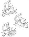
- FIGS. 1 to 3 comprise a frame 10 comprising a base plate 12 of generally rectangular shape and provided at each of its corners with horns 13, 14, 16 forming means for attaching a bracelet not shown in the drawing. . These horns are each pierced with a hole 18 for receiving, in a manner well known to those skilled in the art, a bar engaged in a loop whose end of the bracelet is provided.
- the boxes further comprise a housing 20 and a hinge 22 forming means for connecting the housing 20 to its frame 10, and a bezel 24 pivotally mounted on the frame 10 by a hinge 25 described in more detail for reference.
- the housing 20 will be described more precisely with reference to FIG.
- the articulation comprises two parallelepipedal pieces 26 arranged parallel to each other and to the axes passing through the holes 18.
- the parts 26 are each provided with a groove 28.
- the housing 20 is provided at one of its ends with two cylindrical pins which are not visible in the drawing, each engaged in one of the grooves 28 and together forming a slide which allows both a translation movement and pivoting. In this way, the housing 20 can slide on the frame 12 and rotate 180 °, as shown by the arrows f1 and f2, so that either one of its faces is apparent.
- the grooves are provided at their ends with notches for holding the housing in one or other of its extreme positions.
- These notches may be of the spring ball type, of the same type as will be described with reference to Figures 4a and 4b, or any other type well known to those skilled in the art.
- the hinge 22 of the embodiment of Figure 2 is of the ball type. It comprises a stud 30 secured to the plate 12, disposed midway between the two horns 13 and 14 and provided with a not visible housing in the drawing, open towards the central portion of the frame 10.
- the housing 20 is of general shape cuboid.
- a rod 32 is fixed, by one of its ends, to one of the sides of the housing 20.
- the other end carries a sphere 34 engaged and retained in the housing of the stud 30.
- There are many ways to maintain the sphere 34 movable in rotation in the housing for example by crimping the hole, or by any other means, well known to those skilled in the art.
- Such articulation also makes it possible to rotate the housing 20 on the frame 10. To this end, it is sufficient to tilt the housing 20 about an axis parallel to the axes passing through the holes 18 of bars, and then, when the rod 32 is substantially perpendicular to the surface of the plate 12, to rotate 180 ° about the axis of the rod 32, finally to fold the housing 20 on its frame 10, as shown by the arrows f1 and f2 .
- the chassis 10 may be provided with means for positioning the housing 20, for example a spring ball disposed in a complementary stud facing the stud 30 and cooperating with a notch that the housing 20 has on its face opposite to that carrying the rod 32. These means have not been shown, to avoid overloading the drawing.
- FIG. 3 illustrates a third embodiment of a box according to the invention.
- the hinge 22 is formed of two hinges 36 and 38 orthogonal. More specifically, the hinge 36 comprises two feet 40 and 42, respectively adjacent to the horns 13 and 14, and a bar 44, disposed between the two feet 40 and 42.
- the feet 40 and 42 are pierced with holes 46 in which are engaged with pins forming pivot, not visible in the drawing, fixed rigidly in the bar 44.
- the hinge 36 therefore allows a rotation about an axis AA parallel to the axes passing through the holes 18 of bars, represented by the arrow f1.
- the hinge 38 is made by means of a shaft B-B axis, only this axis being shown in the drawing, perpendicular to the axis A-A.
- This rod is integral with the housing 20 and engaged in a hole of the bar 44.
- the hinge 38 thus allows rotation about the axis B-B, as indicated by the arrow f2.
- the housing 20 is then rotated about the axis BB, which makes work the hinge 38 .
- the hinge 22 constitutes means for connecting the housing 20 to the frame 12, allowing a relative movement of one with reference to the other, to allow one of the faces of the housing 20 either facing the chassis, the other being apparent, and move from one to the other without even having to remove the watch from the wrist.
- the box is further provided with a bezel 24 to maintain the housing 20 on its frame 10, without risk of recess.
- the frame 10 comprises, housed in its horns 13 to 17, two spring balls 46 held in their housing by crimping, while the bezel carries, in each of the lateral branches, a piston 48 slidably mounted in a cylindrical hole and opening into a recess 50.
- the spring balls 46 are arranged such that, when the telescope is folded over the housing 20, they are engage in one of the dies 50, thus forming a notch.
- it is sufficient to simultaneously press on the two pistons 48, which releases the balls 46 from the cores 50 and thus allows the displacement of the telescope 24 with reference to the frame 12.
- the bezel 24 plays a very important aesthetic role.
- a change of bezel allows, therefore, a considerable change in the appearance of the watch.
- the hinge 25, shown in Figures 5a and 5b has two parts, a housing 52, adjacent to the plate 12, and a pivot shaft 54 integral with the bezel 24.
- the housing 52 is of cylindrical general shape, of axis parallel to the axes passing through the holes 18.
- the wall that defines it is provided with a slot 52a along its entire length.
- the shaft 54 is of rectangular section, diagonally slightly smaller than the diameter of the housing and whose short side is smaller than the width of the slot 52a.
- the shaft 54 is arranged so that, in the closed position of the telescope 24, as shown in FIG. 5a, a plane passing through the middle of the slot 52a and through the axis of the shaft 54 intersects the latter parallel to the small side. In this way, the shaft 54 can only pivot in its housing 52.
- the housing 20 is advantageously constituted of two identical shells, such as that 56 shown in Figure 6.
- This shell 56 has a generally rectangular shape with two long sides 56a and two small sides 56b. Their slice, visible in the drawing, is provided with a groove 56c, intended to receive a seal 58.
- the rear face of the shell, as shown, carries a watch glass 60 fixed by gluing or by any other means known to those skilled in the art.
- One of the long sides is provided with a cylindrical hole 56d intended to allow the passage of a time setting rod, of the usual type.
- One of the short sides is extended by a flange 56e provided with two holes 56f through it from one side to the other.
- the other side has a groove 56g, also pierced with two holes, which are identified by the reference 56h. These are blind and tapped.
- the shells 56 After the shells 56 have each been equipped with a watch movement, not shown in the drawing, and one of the grooves 56c of a seal 58, they are arranged one above the other, head to tail, of such that the flange 56e of one engages in the groove 56g of the other.
- the holes 56d and 56f are arranged so that they lie in the extension of each other. Also, when the two shells are in place, it is possible to assemble them to one another by four screws not shown in the drawing, thus forming the housing 20. These screws can advantageously allow, in addition, the fixing of the part of the hinged joint of the housing 20.
- Such a watch case offers the advantage of actively participating in the protection of its delicate parts.
- the time setting ring can be covered by the bezel, so that the risk of hanging is virtually nonexistent. It also allows the person skilled in the art, as is partially explained above, innumerable aesthetic developments, by means of a simple construction structure and having no delicate part.
Landscapes
- Physics & Mathematics (AREA)
- General Physics & Mathematics (AREA)
- Casings For Electric Apparatus (AREA)
- Pivots And Pivotal Connections (AREA)
- Inorganic Insulating Materials (AREA)
- Thermotherapy And Cooling Therapy Devices (AREA)
- Magnetic Treatment Devices (AREA)
- Electric Clocks (AREA)
- Vehicle Step Arrangements And Article Storage (AREA)
- Details Of Measuring And Other Instruments (AREA)
Claims (9)
- Uhrgehäuse, welches- einen mit Befestigungseinrichtungen für ein Armband (13 bis 16) versehenen Grundträger (10),- eine mit zwei im Wesentlichen zueinander parallelen Flächen versehene Kapsel (20), von denen wenigstens eine mit einem Glas (60) versehen ist, das dazu bestimmt ist, das Ablesen der Uhrzeit von durch es hindurch sichtbaren Anzeigeeinrichtungen zu erlauben,- Einrichtungen (22) zum Verbinden der Kapsel (20) mit dem Grundträger (10), die eine Relativbewegung bezüglich einander derart erlauben, dass es möglich ist, die Kapsel auf dem Grundträger zu drehen und folglich zu wählen, welche der Flächen sichtbar ist,- einen auf dem Grundträger (10) angebrachten Glasdeckel (24) und- ein Scharnier (25) aufweist, das den Glasdeckel (24) mit dem Grundträger (10) gelenkig verbindet und es dem Glasdeckel (24) erlaubt, eine erste, geschlossene Position, in der er die Kapsel (20) an ihrem Umfang bedeckt und ihr Verschieben bezüglich des Grundträgers (10) verhindert, und eine zweite, offene Position einzunehmen, in der die Kapsel (20) bezogen auf den Grundträger bewegt werden kann,dadurch gekennzeichnet,- dass es weiterhin Verriegelungseinrichtungen (46) für den Glasdeckel (24) auf dem Grundträger (10) aufweist, die so ausgelegt sind, dass sie eine erste Position, in der der Glasdeckel an dem Grundträger festgelegt ist, wenn er sich in der geschlossenen Position befindet, und eine zweite Position einnehmen können, in der der Glasdeckel (24) in jeder Position bezogen auf den Grundträger verschoben werden kann, und- dass das Scharnier (25) in abnehmbarer Bauweise und so ausgelegt ist, dass der Glasdeckel in seiner offenen Position vom Grundträger getrennt werden kann.
- Gehäuse nach Anspruch 1, dadurch gekennzeichnet, dass die Verbindungseinrichtungen (22) eine Führungsrinne (28) und einen Schlitten aufweisen, wobei die eine dem Grundträger (10) und der andere der Kapsel (20) zugeordnet ist, die so ausgelegt sind, dass sie Translations- und Schwenkbewegungen der Kapsel (20) auf dem Grundträger (10) erlauben, wobei die Führungsrinne (28) lang genug ist, um das eine oder das andere Ende der Kapsel (20) an das eine oder das andere Ende des Grundträgers (10) zu führen.
- Gehäuse nach einem der Ansprüche 1 und 2, dadurch gekennzeichnet, dass die Verbindungseinrichtungen (22) einen Kugelbolzen (34) und einen Sitz aufweisen, der für die Aufnahme des Kugelbolzens bestimmt ist, wobei der eine dem Grundträger (10) und der andere der Kapsel (20) zugeordnet ist, und beide eine Drehung der Kapsel (20) auf dem Grundträger (10) um zwei rechtwinklige Achsen derart erlauben, dass ein Herumdrehen der Kapsel auf dem Grundträger zugelassen ist.
- Gehäuse nach einem der Ansprüche 1 und 2, dadurch gekennzeichnet, dass die Verbindungseinrichtungen (22) zwei Scharniere (36, 38) aufweisen, die Schwenkachsen (A-A, B-B) definieren, die zueinander senkrecht sind, wobei sich das erste (36) um eine Achse (A-A) dreht, die im Wesentlichen parallel zur Ebene des Grundträgers (10) ist, und einen ersten Teil (46) aufweist, der mit dem Grundträger (10) fest verbunden ist, das zweite (38) einen ersten mit der Kapsel fest verbundenen Teil aufweist, und die beiden Scharniere zweite Teile (44) aufweisen, die miteinander fest verbunden sind und bezogen auf ihren jeweiligen ersten Teil angelenkt sind, wodurch das Herumdrehen der Kapsel (20) auf dem Grundträger (10) zugelassen ist.
- Gehäuse nach einem der Ansprüche 1 bis 4, dadurch gekennzeichnet, dass es weiterhin mit einer Krone zum Einstellen der Uhrzeit versehen ist und dass sich der Glasdeckel (24), wenn er sich in der geschlossenen Position befindet, über die Krone erstreckt.
- Gehäuse nach einem der Ansprüche 1 bis 5, dadurch gekennzeichnet, dass die Kapsel zwei Schalen (56) mit gleicher Form aufweist, die so aneinander festgelegt sind, dass sie bezogen auf die Mitte der Kapsel eine Kugelsymmetrie bilden.
- Gehäuse nach Anspruch 6, dadurch gekennzeichnet, dass die Schalen jeweils Wände (56a, 56b) aufweisen, die paarweise parallel angeordnet sind und einen Sitz bilden, der für die Aufnahme eines Uhrgehäuses bestimmt ist, wobei eine der Wände durch einen Flansch (56e) verlängert ist, während die zu ihr parallele Wand mit einer Nut (56g) mit einer zum Flansch (56e) komplementären Form versehen ist, wobei die Schalen entgegengesetzt zueinander angeordnet sind, und der Flansch der einen in die Nut der anderen eingreift.
- Gehäuse nach Anspruch 7, dadurch gekennzeichnet, dass die Schalen aneinander mittels Schrauben befestigt sind, die in Löcher eingreifen, die die Flansche und die Wände in ihrem die Nut bildenden Teil aufweisen.
- Gehäuse nach Anspruch 8, dadurch gekennzeichnet, dass jede der Schalen zwei Wände (56a) aufweist, die zu den Wänden senkrecht sind, die durch einen Flansch verlängert bzw. mit einer Nut versehen sind, wobei eine der senkrechten Wände jeder Schale von einem zylindrischen Loch (56d) durchbohrt ist, das dazu bestimmt ist, als Durchgang für eine Stellwelle zu dienen, so dass die Kapsel für die Aufnahme von zwei Uhrwerken dienen kann.
Priority Applications (5)
| Application Number | Priority Date | Filing Date | Title |
|---|---|---|---|
| EP03000279A EP1437635B1 (de) | 2003-01-08 | 2003-01-08 | Uhrgehäuse |
| DE60309428T DE60309428T2 (de) | 2003-01-08 | 2003-01-08 | Uhrgehäuse |
| AT03000279T ATE344475T1 (de) | 2003-01-08 | 2003-01-08 | Uhrgehäuse |
| CN200480001992.4A CN1723421A (zh) | 2003-01-08 | 2004-01-08 | 表壳 |
| PCT/IB2004/000151 WO2004063019A2 (fr) | 2003-01-08 | 2004-01-08 | Boite de montre |
Applications Claiming Priority (1)
| Application Number | Priority Date | Filing Date | Title |
|---|---|---|---|
| EP03000279A EP1437635B1 (de) | 2003-01-08 | 2003-01-08 | Uhrgehäuse |
Publications (2)
| Publication Number | Publication Date |
|---|---|
| EP1437635A1 EP1437635A1 (de) | 2004-07-14 |
| EP1437635B1 true EP1437635B1 (de) | 2006-11-02 |
Family
ID=32479891
Family Applications (1)
| Application Number | Title | Priority Date | Filing Date |
|---|---|---|---|
| EP03000279A Expired - Lifetime EP1437635B1 (de) | 2003-01-08 | 2003-01-08 | Uhrgehäuse |
Country Status (5)
| Country | Link |
|---|---|
| EP (1) | EP1437635B1 (de) |
| CN (1) | CN1723421A (de) |
| AT (1) | ATE344475T1 (de) |
| DE (1) | DE60309428T2 (de) |
| WO (1) | WO2004063019A2 (de) |
Cited By (2)
| Publication number | Priority date | Publication date | Assignee | Title |
|---|---|---|---|---|
| WO2011163173A1 (en) | 2010-06-21 | 2011-12-29 | Crown International Properties Establishment | System and method for easy change jewelry case cover |
| EP4105735A1 (de) * | 2021-06-18 | 2022-12-21 | Omega SA | Bedienbares verkleidungselement |
Families Citing this family (11)
| Publication number | Priority date | Publication date | Assignee | Title |
|---|---|---|---|---|
| EP1840678B1 (de) * | 2006-03-30 | 2010-09-01 | Richemont International S.A. | Umkehrbare Uhr |
| ATE417521T1 (de) * | 2006-09-19 | 2009-01-15 | Montres Breguet Sa | Zweiseitige armbanduhr |
| CN1945464B (zh) * | 2006-09-21 | 2011-12-21 | 李宁体育(上海)有限公司 | 一种可旋转手表 |
| EP2487548B1 (de) * | 2011-02-11 | 2018-01-10 | Montres Breguet SA | Umkehrmechanismus der Drehbewegung eines Gehäuses |
| EP2672331B1 (de) * | 2012-06-06 | 2017-11-15 | Omega SA | Uhrgehäuse mit Ausstattung mit verbesserter Fixierung |
| CN102819215B (zh) * | 2012-08-31 | 2013-07-10 | 珠海罗西尼表业有限公司 | 一种手表 |
| ITFI20130088A1 (it) * | 2013-04-23 | 2014-10-24 | Hi Tek Office S R L | Orologio da polso "reverse". |
| CN109036496B (zh) * | 2018-08-03 | 2020-11-24 | 黄琴 | 一种防震式仪器仪表装置 |
| CN110209042B (zh) * | 2019-04-13 | 2020-09-22 | 东阳宗添电子科技有限公司 | 一种多种方式显示时间的挂钟 |
| JP2023034651A (ja) * | 2021-08-31 | 2023-03-13 | セイコーエプソン株式会社 | 腕時計、及びバンド |
| CN114911150A (zh) * | 2022-04-26 | 2022-08-16 | 鄢立恒 | 一种红外物体探测器 |
Family Cites Families (8)
| Publication number | Priority date | Publication date | Assignee | Title |
|---|---|---|---|---|
| CH159982A (fr) * | 1931-03-04 | 1933-02-15 | Alfred Chauvot Rene | Montre-bracelet comportant une boîte susceptible de se retourner entièrement sur elle-même dans un support. |
| FR847726A (fr) * | 1938-12-19 | 1939-10-16 | Georges Meyer Sa Des Ets | Perfectionnements aux bracelets-montres |
| GB1372464A (en) * | 1972-02-14 | 1974-10-30 | Modell Und Plastspielwaren Kom | Toy clock |
| FR2665546B1 (fr) * | 1990-08-01 | 1995-04-21 | Boucheron | Montre-bracelet avec boitier a couvercle interchangeable. |
| DE9204095U1 (de) * | 1992-03-26 | 1992-05-07 | Chronoswiss Uhren GmbH, 8000 M∢nchen | Uhr |
| DE9408566U1 (de) * | 1994-05-25 | 1994-11-03 | Brand, Rainer, 63872 Heimbuchenthal | Armbanduhr |
| CH689338A5 (fr) * | 1996-01-29 | 1999-02-26 | Patek Philippe Sa | Pièce d'horlogerie, notamment montre de poche, munie d'un couvercle sur chaque face. |
| FR2804217A1 (fr) * | 2000-01-24 | 2001-07-27 | Michael Selam | Boitier pour montre bracelet rectangulaire avec couvercle et boite-mouvement basculante |
-
2003
- 2003-01-08 AT AT03000279T patent/ATE344475T1/de not_active IP Right Cessation
- 2003-01-08 DE DE60309428T patent/DE60309428T2/de not_active Expired - Fee Related
- 2003-01-08 EP EP03000279A patent/EP1437635B1/de not_active Expired - Lifetime
-
2004
- 2004-01-08 WO PCT/IB2004/000151 patent/WO2004063019A2/fr not_active Ceased
- 2004-01-08 CN CN200480001992.4A patent/CN1723421A/zh active Pending
Cited By (3)
| Publication number | Priority date | Publication date | Assignee | Title |
|---|---|---|---|---|
| WO2011163173A1 (en) | 2010-06-21 | 2011-12-29 | Crown International Properties Establishment | System and method for easy change jewelry case cover |
| EP2521942A4 (de) * | 2010-06-21 | 2013-07-31 | Crown Internat Properties Establishment | System und verfahren für leichten austausch des deckels eines schmuckkastens |
| EP4105735A1 (de) * | 2021-06-18 | 2022-12-21 | Omega SA | Bedienbares verkleidungselement |
Also Published As
| Publication number | Publication date |
|---|---|
| DE60309428T2 (de) | 2007-10-11 |
| WO2004063019A2 (fr) | 2004-07-29 |
| DE60309428D1 (de) | 2006-12-14 |
| EP1437635A1 (de) | 2004-07-14 |
| WO2004063019A3 (fr) | 2004-11-11 |
| WO2004063019B1 (fr) | 2004-12-23 |
| CN1723421A (zh) | 2006-01-18 |
| ATE344475T1 (de) | 2006-11-15 |
Similar Documents
| Publication | Publication Date | Title |
|---|---|---|
| EP1116075B1 (de) | Umkehrbare armbanduhr | |
| WO2004063019A2 (fr) | Boite de montre | |
| EP1875826A1 (de) | Schmuckstück mit eimem beweglichen Element | |
| EP1475679A1 (de) | Verfahren zum Anzeigen der Mondphasen, insbesondere in einem Uhrwerk | |
| EP1404190A1 (de) | Schwenkbarer offener ring | |
| EP4176755A1 (de) | Anbringung eines faserstrangs eines armbands an einem armbanduhrgehäuse | |
| EP1731052B1 (de) | Hals- oder Armband mit regelmässig angeordneten Gliedern auf einem flexiblen Band | |
| EP1047982A1 (de) | Uhrengehäuse | |
| EP2120625B1 (de) | Uhrarmband | |
| CH696090A5 (fr) | Montre-bracelet à boîtier réversible. | |
| CH715003B1 (fr) | Système d'attache d'un bracelet à une boîte de montre. | |
| WO2018083388A1 (fr) | Bijou | |
| WO2023078836A1 (fr) | Assemblage d'un brin de bracelet sur une boîte de montre | |
| FR3052566B1 (fr) | Charniere pour monture de lunettes comprenant au moins une butee interne | |
| EP1189117B1 (de) | Armbanduhr mit umkehrbarem Gehäuse | |
| CH703497A2 (fr) | Article portable. | |
| CH700416B1 (fr) | Coffret pour montre ou bijou. | |
| FR2776785A1 (fr) | Ensemble constitutif de l'habillement d'une montre | |
| EP1071976A1 (de) | Modulare brillenfassung | |
| CH682290A5 (en) | Wrist watch bracelet - has holder between two sections of bracelet on opposite side to watch, designed to hold second instrument or container | |
| EP1475680B1 (de) | Verfahren zum Anzeigen der Mondphasen, insbesondere in einem Uhrwerk | |
| EP1859325B1 (de) | Uhr | |
| EP4632501A1 (de) | Anordnung eines armbandstrangs an einem uhrengehäuse | |
| CH693834A5 (fr) | Montre-bracelet comportant un boîtier mobile. | |
| CH696503A5 (fr) | Dispositif d'affichage des phases de la lune, notamment dans une pièce d'horlogerie. |
Legal Events
| Date | Code | Title | Description |
|---|---|---|---|
| PUAI | Public reference made under article 153(3) epc to a published international application that has entered the european phase |
Free format text: ORIGINAL CODE: 0009012 |
|
| AK | Designated contracting states |
Kind code of ref document: A1 Designated state(s): AT BE BG CH CY CZ DE DK EE ES FI FR GB GR HU IE IT LI LU MC NL PT SE SI SK TR |
|
| AX | Request for extension of the european patent |
Extension state: AL LT LV MK RO |
|
| 17P | Request for examination filed |
Effective date: 20041209 |
|
| AKX | Designation fees paid |
Designated state(s): AT BE BG CH CY CZ DE DK EE ES FI FR GB GR HU IE IT LI LU MC NL PT SE SI SK TR |
|
| GRAP | Despatch of communication of intention to grant a patent |
Free format text: ORIGINAL CODE: EPIDOSNIGR1 |
|
| GRAS | Grant fee paid |
Free format text: ORIGINAL CODE: EPIDOSNIGR3 |
|
| GRAA | (expected) grant |
Free format text: ORIGINAL CODE: 0009210 |
|
| AK | Designated contracting states |
Kind code of ref document: B1 Designated state(s): AT BE BG CH CY CZ DE DK EE ES FI FR GB GR HU IE IT LI LU MC NL PT SE SI SK TR |
|
| PG25 | Lapsed in a contracting state [announced via postgrant information from national office to epo] |
Ref country code: IT Free format text: LAPSE BECAUSE OF FAILURE TO SUBMIT A TRANSLATION OF THE DESCRIPTION OR TO PAY THE FEE WITHIN THE PRESCRIBED TIME-LIMIT;WARNING: LAPSES OF ITALIAN PATENTS WITH EFFECTIVE DATE BEFORE 2007 MAY HAVE OCCURRED AT ANY TIME BEFORE 2007. THE CORRECT EFFECTIVE DATE MAY BE DIFFERENT FROM THE ONE RECORDED. Effective date: 20061102 Ref country code: IE Free format text: LAPSE BECAUSE OF FAILURE TO SUBMIT A TRANSLATION OF THE DESCRIPTION OR TO PAY THE FEE WITHIN THE PRESCRIBED TIME-LIMIT Effective date: 20061102 Ref country code: CZ Free format text: LAPSE BECAUSE OF FAILURE TO SUBMIT A TRANSLATION OF THE DESCRIPTION OR TO PAY THE FEE WITHIN THE PRESCRIBED TIME-LIMIT Effective date: 20061102 Ref country code: SI Free format text: LAPSE BECAUSE OF FAILURE TO SUBMIT A TRANSLATION OF THE DESCRIPTION OR TO PAY THE FEE WITHIN THE PRESCRIBED TIME-LIMIT Effective date: 20061102 Ref country code: FI Free format text: LAPSE BECAUSE OF FAILURE TO SUBMIT A TRANSLATION OF THE DESCRIPTION OR TO PAY THE FEE WITHIN THE PRESCRIBED TIME-LIMIT Effective date: 20061102 Ref country code: SK Free format text: LAPSE BECAUSE OF FAILURE TO SUBMIT A TRANSLATION OF THE DESCRIPTION OR TO PAY THE FEE WITHIN THE PRESCRIBED TIME-LIMIT Effective date: 20061102 Ref country code: NL Free format text: LAPSE BECAUSE OF FAILURE TO SUBMIT A TRANSLATION OF THE DESCRIPTION OR TO PAY THE FEE WITHIN THE PRESCRIBED TIME-LIMIT Effective date: 20061102 Ref country code: AT Free format text: LAPSE BECAUSE OF FAILURE TO SUBMIT A TRANSLATION OF THE DESCRIPTION OR TO PAY THE FEE WITHIN THE PRESCRIBED TIME-LIMIT Effective date: 20061102 |
|
| REG | Reference to a national code |
Ref country code: GB Ref legal event code: FG4D Free format text: NOT ENGLISH |
|
| REG | Reference to a national code |
Ref country code: IE Ref legal event code: FG4D Free format text: LANGUAGE OF EP DOCUMENT: FRENCH |
|
| REG | Reference to a national code |
Ref country code: CH Ref legal event code: EP |
|
| REF | Corresponds to: |
Ref document number: 60309428 Country of ref document: DE Date of ref document: 20061214 Kind code of ref document: P |
|
| REG | Reference to a national code |
Ref country code: CH Ref legal event code: NV Representative=s name: INFOSUISSE INFORMATION HORLOGERE ET INDUSTRIELLE |
|
| PG25 | Lapsed in a contracting state [announced via postgrant information from national office to epo] |
Ref country code: MC Free format text: LAPSE BECAUSE OF NON-PAYMENT OF DUE FEES Effective date: 20070131 |
|
| PG25 | Lapsed in a contracting state [announced via postgrant information from national office to epo] |
Ref country code: SE Free format text: LAPSE BECAUSE OF FAILURE TO SUBMIT A TRANSLATION OF THE DESCRIPTION OR TO PAY THE FEE WITHIN THE PRESCRIBED TIME-LIMIT Effective date: 20070202 Ref country code: DK Free format text: LAPSE BECAUSE OF FAILURE TO SUBMIT A TRANSLATION OF THE DESCRIPTION OR TO PAY THE FEE WITHIN THE PRESCRIBED TIME-LIMIT Effective date: 20070202 Ref country code: BG Free format text: LAPSE BECAUSE OF FAILURE TO SUBMIT A TRANSLATION OF THE DESCRIPTION OR TO PAY THE FEE WITHIN THE PRESCRIBED TIME-LIMIT Effective date: 20070202 |
|
| PG25 | Lapsed in a contracting state [announced via postgrant information from national office to epo] |
Ref country code: ES Free format text: LAPSE BECAUSE OF FAILURE TO SUBMIT A TRANSLATION OF THE DESCRIPTION OR TO PAY THE FEE WITHIN THE PRESCRIBED TIME-LIMIT Effective date: 20070213 |
|
| GBT | Gb: translation of ep patent filed (gb section 77(6)(a)/1977) |
Effective date: 20070131 |
|
| PG25 | Lapsed in a contracting state [announced via postgrant information from national office to epo] |
Ref country code: PT Free format text: LAPSE BECAUSE OF FAILURE TO SUBMIT A TRANSLATION OF THE DESCRIPTION OR TO PAY THE FEE WITHIN THE PRESCRIBED TIME-LIMIT Effective date: 20070402 |
|
| NLV1 | Nl: lapsed or annulled due to failure to fulfill the requirements of art. 29p and 29m of the patents act | ||
| REG | Reference to a national code |
Ref country code: IE Ref legal event code: FD4D |
|
| PLBE | No opposition filed within time limit |
Free format text: ORIGINAL CODE: 0009261 |
|
| STAA | Information on the status of an ep patent application or granted ep patent |
Free format text: STATUS: NO OPPOSITION FILED WITHIN TIME LIMIT |
|
| 26N | No opposition filed |
Effective date: 20070803 |
|
| BERE | Be: lapsed |
Owner name: STRAUSS, JONATHAN M. Effective date: 20070131 |
|
| PG25 | Lapsed in a contracting state [announced via postgrant information from national office to epo] |
Ref country code: BE Free format text: LAPSE BECAUSE OF NON-PAYMENT OF DUE FEES Effective date: 20070131 |
|
| PG25 | Lapsed in a contracting state [announced via postgrant information from national office to epo] |
Ref country code: GR Free format text: LAPSE BECAUSE OF FAILURE TO SUBMIT A TRANSLATION OF THE DESCRIPTION OR TO PAY THE FEE WITHIN THE PRESCRIBED TIME-LIMIT Effective date: 20070203 |
|
| PGFP | Annual fee paid to national office [announced via postgrant information from national office to epo] |
Ref country code: CH Payment date: 20080201 Year of fee payment: 6 |
|
| PGFP | Annual fee paid to national office [announced via postgrant information from national office to epo] |
Ref country code: GB Payment date: 20080129 Year of fee payment: 6 |
|
| PGFP | Annual fee paid to national office [announced via postgrant information from national office to epo] |
Ref country code: FR Payment date: 20080123 Year of fee payment: 6 Ref country code: DE Payment date: 20080327 Year of fee payment: 6 |
|
| PG25 | Lapsed in a contracting state [announced via postgrant information from national office to epo] |
Ref country code: EE Free format text: LAPSE BECAUSE OF FAILURE TO SUBMIT A TRANSLATION OF THE DESCRIPTION OR TO PAY THE FEE WITHIN THE PRESCRIBED TIME-LIMIT Effective date: 20061102 |
|
| PG25 | Lapsed in a contracting state [announced via postgrant information from national office to epo] |
Ref country code: LU Free format text: LAPSE BECAUSE OF NON-PAYMENT OF DUE FEES Effective date: 20070108 Ref country code: CY Free format text: LAPSE BECAUSE OF FAILURE TO SUBMIT A TRANSLATION OF THE DESCRIPTION OR TO PAY THE FEE WITHIN THE PRESCRIBED TIME-LIMIT Effective date: 20061102 |
|
| REG | Reference to a national code |
Ref country code: CH Ref legal event code: PL |
|
| GBPC | Gb: european patent ceased through non-payment of renewal fee |
Effective date: 20090108 |
|
| PG25 | Lapsed in a contracting state [announced via postgrant information from national office to epo] |
Ref country code: HU Free format text: LAPSE BECAUSE OF FAILURE TO SUBMIT A TRANSLATION OF THE DESCRIPTION OR TO PAY THE FEE WITHIN THE PRESCRIBED TIME-LIMIT Effective date: 20070503 Ref country code: TR Free format text: LAPSE BECAUSE OF FAILURE TO SUBMIT A TRANSLATION OF THE DESCRIPTION OR TO PAY THE FEE WITHIN THE PRESCRIBED TIME-LIMIT Effective date: 20061102 |
|
| PG25 | Lapsed in a contracting state [announced via postgrant information from national office to epo] |
Ref country code: LI Free format text: LAPSE BECAUSE OF NON-PAYMENT OF DUE FEES Effective date: 20090131 Ref country code: DE Free format text: LAPSE BECAUSE OF NON-PAYMENT OF DUE FEES Effective date: 20090801 Ref country code: CH Free format text: LAPSE BECAUSE OF NON-PAYMENT OF DUE FEES Effective date: 20090131 |
|
| REG | Reference to a national code |
Ref country code: FR Ref legal event code: ST Effective date: 20091030 |
|
| PG25 | Lapsed in a contracting state [announced via postgrant information from national office to epo] |
Ref country code: GB Free format text: LAPSE BECAUSE OF NON-PAYMENT OF DUE FEES Effective date: 20090108 |
|
| PG25 | Lapsed in a contracting state [announced via postgrant information from national office to epo] |
Ref country code: FR Free format text: LAPSE BECAUSE OF NON-PAYMENT OF DUE FEES Effective date: 20090202 |