EP1437671A2 - Procédé et dispositif pour fournir des informations sur pneumatiques - Google Patents
Procédé et dispositif pour fournir des informations sur pneumatiques Download PDFInfo
- Publication number
- EP1437671A2 EP1437671A2 EP04000132A EP04000132A EP1437671A2 EP 1437671 A2 EP1437671 A2 EP 1437671A2 EP 04000132 A EP04000132 A EP 04000132A EP 04000132 A EP04000132 A EP 04000132A EP 1437671 A2 EP1437671 A2 EP 1437671A2
- Authority
- EP
- European Patent Office
- Prior art keywords
- tire
- customer
- model
- information
- simulation
- Prior art date
- Legal status (The legal status is an assumption and is not a legal conclusion. Google has not performed a legal analysis and makes no representation as to the accuracy of the status listed.)
- Withdrawn
Links
Images






Classifications
-
- G—PHYSICS
- G06—COMPUTING OR CALCULATING; COUNTING
- G06F—ELECTRIC DIGITAL DATA PROCESSING
- G06F30/00—Computer-aided design [CAD]
- G06F30/10—Geometric CAD
- G06F30/15—Vehicle, aircraft or watercraft design
-
- B—PERFORMING OPERATIONS; TRANSPORTING
- B60—VEHICLES IN GENERAL
- B60C—VEHICLE TYRES; TYRE INFLATION; TYRE CHANGING; CONNECTING VALVES TO INFLATABLE ELASTIC BODIES IN GENERAL; DEVICES OR ARRANGEMENTS RELATED TO TYRES
- B60C19/00—Tyre parts or constructions not otherwise provided for
-
- G—PHYSICS
- G06—COMPUTING OR CALCULATING; COUNTING
- G06F—ELECTRIC DIGITAL DATA PROCESSING
- G06F30/00—Computer-aided design [CAD]
- G06F30/20—Design optimisation, verification or simulation
-
- G—PHYSICS
- G06—COMPUTING OR CALCULATING; COUNTING
- G06F—ELECTRIC DIGITAL DATA PROCESSING
- G06F30/00—Computer-aided design [CAD]
- G06F30/20—Design optimisation, verification or simulation
- G06F30/23—Design optimisation, verification or simulation using finite element methods [FEM] or finite difference methods [FDM]
Definitions
- the present invention relates to a tire informationproviding method and an apparatus thereof capable of providing on-target tire information that is truly wanted by the customer.
- Tire manufacturers provide information on riding comfort, sport performance, wet performance, or silence of respective tires through media such as TV commercials, newspapers, magazines, catalogues or the Internet.
- the present invention has been devised in view of the above-described circumstances. More particularly,in the present invention, at least one tire, road surface condition, tire mounting condition and evaluation parameter are set at requests of customers and simulations are performed on a computer on the basis of those conditions for calculating evaluation parameters. By providing those evaluation parameters to customers, it is possible to provide on-target tire information in accordance with various needs of customers. This is the main object of the present invention.
- the method of the present invention is a tire information providing method for providing information on at least one tire to a customer comprising the steps of:
- the apparatus of the present invention is a tire information providing apparatus for providing tire information to a customer comprising:
- condition such as tire, road surface, mounting method and evaluation parameter are combined such that tire information corresponding to needs varying from customer to customer can be set and provided. Accordingly, it is possible to the customer with only those pieces of on-target information that a customer truly wants to the customer. This not only meets demands of customers to provide satisfaction but also leads to expanded sales of tires.
- customer may even better understand differences in tire performances. Since customers may learn general tire performance without the necessity of performing actual test drives or similar, labor of both, the tire manufactures and customers can be remarkably reduced.
- FIG. 1 is a block diagram illustrating one example of a tire information providing apparatus (hereinafter also simply referred to as “the apparatus") 1 of the present embodiment.
- the apparatus and method of the present embodiment pieces of tire information that are being wanted by customers are collected and provided on-target. Pieces of tire information meeting demands of customers are identified by using setting condition for at least one kind of tire, wheel, car body, road surface or evaluation parameter etc. Simulation, in which tire is made to run on a computer, is performed on the basis of the condition that has been set by the customers. The set evaluation parameter is calculated through the simulation, and the results are provided to the customers. More detailed explanations will now follow.
- a main computer 2 executing above simulations is provided, for instance, at a tire manufacturer side.
- a plurality of client computers 3 or 6 connected to the main computer 2 through a network are provided at sales offices A, B, C ... of the tire manufacturer and at customer sides A, B, C ... .
- the client computers 3 or 6 and the main computer 2 are interconnected to allow sending and receiving of required information.
- the main computer 2 includes a data storing portion 4 on which various databases and others are stored, and a control portion 5 for performing specified processes by using information stored on the data storing portion 4.
- the data storing portion 4 may be comprised, for instance, of a magnetic disk, wherein files of a tire model database, a wheel model database, a body model database, a road surface model database, a degradation information data portion, a customer information database or an evaluation parameter database are stored.
- the tire model database stores therein two or more kind of tire models Tm that are used for numeric simulation as illustrated in Fig. 2 in visualized form.
- the respective tire model represent physical tires that are object of analysis replaced by a collection of a minute finite number of elements e1, e2, ... . More particularly, coordinates of nodes of respective elements, element numbers, element shapes (solid elements, flat elements), or material properties (elasticity, attenuation coefficients, density) are stored as numeric data.
- the following and other models are arranged such that numerical analysis can be performed through finite element method in the present embodiment.
- the respective tire models Tm is modeled including tread patterns, inner structural materials (carcass, belts, bead cores etc.) and rubber properties (elasticity of rubber materials) of actual tires for achieving even more accurate simulation results.
- the present invention is not to be limited to such an embodiment.
- Fig. 3 illustrates the entire tire model database in visualized form.
- the tire model database includes two or more kind of tire models having different tire size, aspect ratio, or model number (whereby differences are caused in tread patterns and inner structures of tires).
- the respective tire models Tm are assigned with individual tire model names.
- one tire model is comprised of one file (in Figs. 2 and 3, "TMDF1").
- the tire model database is arranged in that, for instance, one piece of information for managing one tire model Tm is stored on a single record (line). More particularly, items such as "manufacturer name” that manufacture the tire, "model number” for specifying the tire, “aspect ratio” of the tire, “rim diameter” of the tire, and “tire size” of the tire, and “tire model name” (above-mentioned file names) in which the tire has been modeled.
- the wheel model database stores therein two or more kind of wheel models Wm that are used for the simulation.
- the respective wheel models Wm represent physical wheels that are object of analysis replaced by a collection of a minute finite number of elements e1, e2... . More particularly, coordinates of nodes of respective elements, element numbers, element shapes, or material properties are stored as numeric data, similar to the case with the tire models.
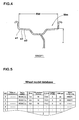
- a plurality of wheel models Wm of different rim diameter r and rim width RW are included.
- the respective wheel models Wm are assigned with individual wheel model names, and according to the present embodiment, one wheel model is comprised of one file (in Fig. 4, "WMDF1").
- Fig. 5 illustrates the entire wheel model database in visualized form.
- the wheel model database is arranged in that, for instance, one piece of information for managing one wheel model Wm is stored on a single record (line). More particularly, items such as "manufacturer names” that manufacture the wheels, “model numbers” for specifying the wheel, “size”, “rim diameter”, “P.C.D” of the wheel, “numbers of holes” for mounting the wheel to shaft, “off-set”, and “wheel model name” (above-mentioned file name) in which the wheel has been modeled.
- the customer may, for instance, browse the wheel model database to easily determine at least one wheel the customer wants to be informed about and a corresponding wheel model Wm.
- the car body database stores therein two or more kind of car body models Bm that are used for the numeric simulation.
- the respective body models Bm represent physical car bodies that are obj ect of analysis replaced by a collection of a finite number of elements E1, E2, ... .
- one body model Bm comprises a main body model Mm, right and left front suspension models FSm disposed in a front portion thereof, and right and left rear suspension models RSm disposed in a rear portion of the main body model Mm.
- Weights, coordinates of center of gravity positions, and moments of inertia are defined for the car main body models Mm.
- the car main body models Mm by rigid elements RE that are not deformed through action of external force. It is not necessary to perform modeling of portions such as the interior members that do substantially not contribute to motional performances of the vehicle, and it is desirable to model only major exterior members.
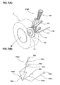
- Fig. 7(A) illustrates one example of a front suspension device FSP that is object of analysis
- Fig. 7(B) illustrates a front suspension model FSm that has been modeled.
- the front suspension device FSP comprises, for instance, an upper arm 10 which one end is pivotally supported at the car main body, a similarly arranged lower arm 11, a knuckle 12 that is supported at the other ends of the respective arms 10, 11, a hub portion 13 that is fixedly attached to the knuckle 12 in a rotating manner and that fixedly attaches a wheel W attached with a tire T, and a spring-loaded damper 14 that is interposed between the knuckle 12 and the car main body.
- a stabilizer 15 for improving the twist rigidity which one end is fixedly attached to the knuckle 12 and which other end is fixedly attached to the car main body is fixedly attached to the knuckle 12.
- Such a front suspension device FSP can assign slip angles to the tire T by tilting the knuckle 12 around a kingpin axis Ka.
- the front suspension model FSm shown as Fig. 7(B) comprises an upper arm model 10m and a lower arm model 11m in which the upper arm 10 and the lower arm 11 are modeled, a knuckle model 12m in which the knuckle 12 is modeled, a hub model 13m in which the hub portion 13 is modeled, a spring-loaded damper model 14m in which the spring-loaded damper 14 is modeled, and a stabilizer model 15m in which the stabilizer 15 is modeled.
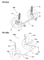
- Fig. 8(A) illustrates one example of a schematic view of the rear suspension device RSP that is object of modeling
- Fig. 8(B) illustrates a rear suspension model RSm in which the above device has been modeled.
- the rear suspension device RSP comprises a pair of trading arms 19, 19 which one end portions are pivotally attached to the car main body and which other end portions include rotatable hubs 17 for mounting the wheels thereto, a torsion beam 20 for connecting between the pair of trading arms 19, 19, and spring-loaded dampers 21, 21 disposed between the torsion beam 20 and the car main body (omitted in the drawing).
- the rear suspension model RSm comprises a hub model 17m in which the hub 17 is modeled, a trading arm model 19m in which the trading arms 19 are modeled, a torsion beam model 20m in which the torsion beam 20 is modeled, and a spring-loaded damper model 21m in which the spring-loaded dampers 21 are modeled.
- the respective suspension models FSm, RSm are established such that they can express mechanical movements.
- the spring-loaded damper models 14m, 21m are defined by linear or non-linear spring elements. Accordingly, telescopic motion in the axial direction is permitted through external force, and internal force is generated in accordance with the amount of telescopic motion.
- the hub models 13m, 17m or the arm models 10m, 11m and 19m are respectively defined as rigid body elements.
- the stabilizer model 15m or the torsion beam model 20m generate a torsion angle through torsional forces, and are modeled as beam elements of torsion generating reaction force accordingly.
- Connecting points Pf1, Pf2..., Pr1, Pr2...that are fixed to the car main body model Mm are defined in the suspension models FSm, Rsm.
- the respective connecting points Pf1 to Pf4 of the front suspension model FSm are fixed points that are fixedly attached to a front portion of the car main body model Mm and which relative positions do not change with respect to each other.
- the respective connecting points Pr1, Pr2 of the rear suspension model RSm are also fixedly attached to a rear portion of the main body model Mm to be described later as fixed points.
- weights, center of gravity positions, and moments of inertia around the center of gravity are defined.
- spring-loaded damper models 14m, 21m spring coefficients and damper attenuation constants are defined.
- beam elements flexural rigidities and torsional rigidities are defined.
- joint conditions include rigid junction in which members are fixed to be unmovable, slide junction in which members are movable in axial directions, joint junction in which members may rotate and pivot in a multiaxial manner or a rotating joint junction in which members are pivotable around a single axis.
- Manners of deformation of such suspension models FSm, RSm upon action of lateral force in cases of application of load or performing turning movements can be simulated on a computer, substantially in a pattern that is similar to a case when using a suspension device of an actual vehicle.
- the car body model Bm includes a plurality of different manufacturers, model numbers and model years. Respective car body models Bm are assigned with respective specific body model names.
- a single car body model is comprised of one file (in Fig. 6, "VMDF1") in the present embodiment. In this respect, all of the body models Bm are illustrated in that they have been modeled on the basis of new car bodies in the present embodiment.
- Fig. 9 illustrates the entire car body model database in visualized form.
- the car body model database information for managing one car body model Bm is stored, for instance, on a single record. More particularly, items such as "name of manufacturer” that manufactures the car body, "model” for defining the vehicle body, “model year” of the car body, shapes of front and rear “suspension” and "car body model name” (above-mentioned file name) in which the vehicle has been modeled are included. Accordingly, it is possible to realign respective items or to designate values for the respective items for retrieval among the car body model database, similar to the tire model database and others.
- the customer may use the car body model database to easily retrieve and determine at least one car body he or she wants to be informed about and a vehicle model Bm which is a modeled version thereof.
- the road surface model database stores therein two or more kind of road surface models Rm that are used for numeric simulations.
- the road surface models Rm represent travel road surfaces that are object of analysis replaced into a finite number of elements e1, e2 ... in divided form. More particularly, coordinates of nodes of respective elements, element numbers, or element shapes are stored as numeric data, similar to the tire models.
- the road surface models Rm include those of a plurality of different friction coefficients of surfaces.
- a normal dry asphalt road surface model NRm a wet road surface model WRm including a water model W in which water of a specified thickness is modeled on a surface thereof, or a snowy road surface model SRm including a snow model S in which snow of a specified thickness is modeled on a surface thereof.
- the asphalt road surface model NRm may be defined, for instance, by using the rigid body elements.
- the water model W and the snow model S can be simply modeled by using, for instance, Euler elements.
- the respective road surface models Rm are assigned with respective peculiar road surface model names.
- One surface ground model is comprised of a single file (in Fig. 10, "RMDF1 to 3").
- Fig. 11 illustrates the entire road surface model database in visualized form.
- the road surface model database stores therein information for managing one road surface model Rm, for instance, on a single record in a correlated manner. More particularly, pieces of information including items such as “road surface conditions”, “ ⁇ ” representing road surface friction coefficient, "thickness of water film”, “thickness of snow”, and “road surface model names” (above-mentioned file names) are illustrated on a single record. Similarly to the tire model database, it is possible to realign respective items or to designate values for the respective items for retrieval among the road surface model database. The customer may use the road surface model database to easily retrieve and determine at least one road surface condition he or she wants to be informed about and a road surface model Rm which is a modeled version of the road surface condition.
- the degradation information database stores therein at least one degradation parameter for reflecting age-related degradation of the tire or the car body to numeric simulation. For instance, when the duration of service of tire becomes large, the rubber will harden, and the amount of wear will become large in substantial proportion to the running distance. As for the car body, the spring constant of the suspension will become less the longer the running distance becomes. In the present embodiment, such phenomena of age-related degradation will be incorporated in the simulation by using the degradation parameter. This makes simulation results come closer to actual results to thereby improve the accuracy of calculation.
- Fig. 12 illustrates one example of a relationship between the duration of service of a tire and a degradation parameter related to the elasticity of the tire rubber.
- the degradation parameter related to the elasticity of the rubber will gradually increase. For instance, where the duration of service of a tire of a customer is given as "a”, the degradation parameter as "b"(%), and the elasticity of a new tire rubber as "c" , the elasticity of the tire rubber of the customer can be corrected by the following equation. c ⁇ b /100
- Fig. 13 illustrates one example of a relationship between the running distance of a tire and the amount of wear of the tire.
- Fig. 14 further illustrates one example of a relationship between the running distance of a tire and degradation parameter of spring constant of suspension of a car body.
- the degradation parameter of spring constant is for performing such corrections.
- the degradation information data portion stores the degradation parameters in form of functions or in a table style. While the present embodiment has been illustrated in that degradation parameters have been set with respect to tire models and suspension models, it is possible to define them for wheels and others.
- the customer information database stores customer information of one customer on a single record (line) .
- one record includes items such as "name of customer”, “e-mail address”, “model of vehicle” owned by the customer, “owned tire” currently used by the customer, “tire 1 of which information has been provided”, “tire 2 of which information has been provided” ... for illustrating histories of model numbers or sizes of tires of which information has been provided in the past, or "simulation condition".
- the evaluation parameter database stores one evaluation parameter on a single record.
- the evaluation parameters are pieces of information for evaluating performances of tires, and include, in addition to general ones such as riding comfort, stability of steering, or wear performance, noise performance (pattern noise, load noise, impact noise, hollow resonance), drainage performance or rolling resistance.
- noise performance pattern noise, load noise, impact noise, hollow resonance
- drainage performance or rolling resistance.
- an evaluation parameter and a calculation parameter required for obtaining the evaluation parameter are stored in a pair.
- the control portion 5 of the present embodiment is illustrated to include a FEM analyzing portion 5a for performing simulation and a Web server 5b.
- the FEM analyzing portion 5a executes a specified simulation on the basis of the finite element method in accordance with conditions that have been set by a customer. It is desirable to use a high-speed computer of high processing performance such as a super computer as the FEM analyzing portion 5a.
- the Web server 5b discloses a part of the data storing portion 4 on a Web through the Internet for simplifying condition settings by customers and to receive results therefrom.
- the Web server 5b sends the received condition to the FEM analyzing portion 5a.
- the system arrangement of the control portion 5 is arbitrary, and the present invention is not limited to such an embodiment.
- Client computers 3 provided at respective sales offices A, B, C ... are connected to the Web server 5b of the main computer 2 such that they can communicate therewith through a network such as the Internet.
- Each client computer 3 comprises at least a display 3a for displaying data and a printer 3b for printing the data. These function as output portions for outputting evaluation parameters.
- Customers A, B ... preferably own environments enabling usage computers 6, 7 with which they can make use of the Internet (WWW) or of e-mail.
- the computers 6, 7 comprise output portions such as at least displays. In this respect, it does not make any distinctions of style, either mobile computers or mobile phones unless it is possible to access the Internet.
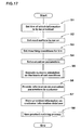
- Fig. 17 illustrates one example of a method for providing tire information according to the present embodiment.
- Step S1 to S4 For determining tire information to be provided to a customer in the method of the present invention, at least one tire, road surface of running, mounting condition and evaluation parameter of which the customer wants to be informed about are set (Step S1 to S4).
- Settings of the tire can be suitably determined, as explained above, by viewing the tire model database through the Internet and upon performing specified retrieval actions.
- a tire model Tm corresponding to the tire can be identified.
- setting of the road surface of running is performed by referring to the road surface model database.
- a road surface model Rm is set in accordance with the road surface of running.
- the wheel model database and the car body database are browsed for respectively setting wheel to be mounted and a car body. The wheel model Wm and the car body model Bm are thus identified.
- Mounting condition include, among others, internal pressure to be filled into the tire and condition of use. While recommended value of tire manufacturers may be used as initial value for the internal pressure, the customer may as well determine them arbitrarily.
- the conditions of use are input when the customer needs to be provided with information related to used tires or used vehicle body, and degradation processes of models are accordingly performed (to be described later). More particularly, numbers of months of use or running distances of the tire are input.
- the set conditions are sent to and stored in the FEM analyzing portion 5a through the Web server 5b.
- two or more kind of conditions are set at least for one of the tire(tire model Tm), the road surface condition (road surface model Rm) and the mounting condition (wheel model Wm, car body model Bm). This will be useful in calculating and comparing evaluation parameters upon varying conditions.
- the tire(tire model Tm) it is desirable at least one kind of tire that the customer is currently using is included therein. This will enable comparison with a currently used tire so that tire information can be more effectively provided.
- two or more kind of tires it is also desirable to include at least one tire recommended by tire manufacturers. Since the tire that is recommended by a tire manufactures is often superior in view of performance, the tire manufacturers may more strongly appeal differences in performance to customers.
- the simulation is then executed on the basis of the set conditions (Step S5).
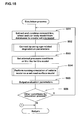
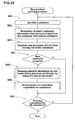
- the simulation is performed by the FEM analyzing portion 5a in accordance with process steps as exemplarily illustrated in Fig. 18.
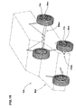
- the FEM analyzing portion 5a is a combination of a hardware and a s oftware, wherein an vehicle model Vm as illustrated in Fig. 19 is created by referring to the respective databases of the data storing portion 4 and by using the set tire model Tm, the wheel model Wm and the car body model Bm (Step S51).
- the vehicle model Vm is set by combining the respective suspension models FSm, RSm of the car body model Mm, the wheel model Wm and the tire model Tm in a numeric manner.
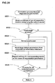
- the correction processes are performed in that conditions of use of respective models constituting the vehicle model are first read from among conditions that have been preliminarily set by the customer (Step S521) .
- the FEM analyzing portion 5a judges, from the conditions of use, the presence or absence of a used model (secondhand model) and if it is judged that no used model is present (N in Step S522), Step 53 and steps following thereafter in Fig. 18 are executed. On the other hand, if it is judged by the FEM analyzing portion 5a that a used model is present from the conditions of use (Y in Step S522), one of the used models is selected (Step S523).
- the FEM analyzing portion 5a refers to the degradation information database to read degradation parameters related to the model in question (Step S524), and the model is corrected on the basis of the degradation parameters (Step S525). Through this correction, it is possible to degrade the hardness of rubber of the tire model Tm, to shallow the tread grooves, and to reduce the spring constants of the suspensions. In this manner, the vehicle model Vm comes even closer to conditions of an actual vehicle.
- Step S53 and steps following thereafter in Fig. 18 are executed.
- Step S523 and steps following thereafter are repeated until correction processes are completed for all models.
- Step S53 in Fig. 18 Upon completion of correction processes through the degradation parameters, required conditions for internal pressure and other various conditions that are necessary are set for the tire model Tm (Step S53 in Fig. 18).
- Such various conditions are conditions that are necessary for calculating evaluation parameters, and moving speed, load, steering wheel input (slip angle) and/or braking input (slip rate) of the vehicle model are, for instance, set when the evaluation parameter is stability of steering.
- the FEM analyzing portion 5a then performs simulation for making the vehicle model Vm run on the set road surface model Rm (Step S54) to output evaluation parameters (Step S55).
- the simulation is performed by, for instance, setting a dynamic equation on the basis of given conditions and the finite element method and by performing time integration thereof. More concretely, it is possible to employ an application software "LS-DYNA" manufactured by Livermore Software Technology Corporation (LSTC) for calculation. Through such simulation, required evaluation parameters can be sequentially calculated and output together with deformation shapes of respective portions, speed, acceleration and force (pressure).
- Step S56 the FEM analyzing portion 5a judges whether other conditions for simulation are set or not (Step S56). When other simulation conditions are set (Y in Step S56), looping of Step S51 and steps following thereafter is performed. When no other conditions are set (N in Step S56) , Step 6 and steps following thereto in Fig. 17 are performed.
- the FEM analyzing portion 5a performs processes of providing information on evaluation parameters to customers (Step S56). These processes include displaying on the display and printing.
- Fig. 21 illustrates one example of information on evaluation parameters. This embodiment illustrates a case in which "wet performance" is set as the evaluation parameter. Results are shown in which three types of tires A, B and C and two types of wheels A, B were set, and in which the following four simulation conditions were set.
- the evaluation parameters are represented in a form of a bar graph with an index of the wet performance of the present condition of use being defined as 100, and evaluation parameters with different conditions are aligned vertically. It is therefore easy to represent comparison.
- the customer can understand that the performance is further degraded when compared to the current condition when using tire B. It can further be objectively understood that the performance will be further worsened when exchanging to wheel B and that an improvement in performance by 27% can be expected when changing from the present condition of use to tire C.
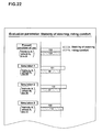
- Fig. 22 illustrates an example of different information with different evaluation parameters.
- the present embodiment illustrates a case in which both of "stability of steering" and “riding comfort” are set as the evaluation parameters.
- the conditions for the tire and the wheel and for the simulation are identical to those of the above (1) to (4). It is illustrated that while the stability of steering largely improves when compared to the present condition of use whenusing tire B in simulation 1, the riding comfort will be slightly degraded.
- Simulation 2 illustrates a further improvement in the steering stability upon exchanging wheels.
- simulation 3 illustrates that the riding comfort is improved while maintaining the current conditions of use and the stability of steering.
- Such information on evaluation parameters as explained above are sent to the computer 6 or 7 that is being operated by the customer, and the customer is allowed to browse by using a Web browser or the like. In other words, the customer side does not require any particular software or similar.
- the above information may also be sent by communication means such as e-mail, facsimile or postal mail. While the above embodiments have been illustrated in that the evaluation parameters are displayed in a comparable manner by using a bar graph, it is possible to employ, for instance, a radar chart or to express them as numeric data, and the methods of expression are variously changeable.
- the method of providing information of the present embodiment it is possible toprovide on-target information a customer truly wants to know.
- the customer may set conditions and receive information on evaluation parameters while being at home, and almost all of the processes are automated. Therefore, labor for both, tire manufacturers and the customers canbe reduced. Complicated calculations such as simulations can be performed on the computer 2 disposed at the tire manufacturer side or the like so that it is not necessary to dispose expensive systems on customer' s sides.
- tire information by setting a plurality of conditions, it is possible to compare performances using evaluation parameters. This is objective and easy to understand. This means that the tire manufacturers may effectively advertise tires to customers. This will improve the buying inclinations of customers so that this will lead to promotion of sales of tires.
- the FEM analyzing portion 5a of the present embodiment stores at least a part of the information on the customer database (Step S7). Among pieces of information to be stored, at least information for defining tires of which information has been provided and simulation conditions are included, and these pieces of information are correlated with the customer. Thereafter, the FEM analyzing portion 5a performs new release product noticing processes (Step S8).
- FIG. 23 One example of process steps of the new product noticing processes is illustrated in Fig. 23.
- the FEM analyzing portion 5a identifies one customer from a top record of the customer information database (Step S81) , and information related to tires of which information has been provided to this customer in the past (for instance, type) is read (Step S82).
- the FEM analyzing portion 5a performs retrieval whether any new products have been added for the read tire on the basis of the tire model database (Step S83). This can be identified by checking model numbers or the presence and absence of registrations of new tires of the same size.
- the FEM analyzing portion 5a uses the new tire for performing simulation by using the same conditions as at the previous time (Step S85), and sends the results to the customer (Step S86).
- the transmission means are preferably e-mails.
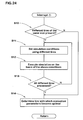
- Fig. 24 illustrates another embodiment of the present invention.
- the present embodiment illustrates a case in which the FEM analyzing portion 5a refers conditions of tires as set bya customer, and in which processes of automatically estimating tires with optimal evaluation parameters are included. In a concrete process, interruption or the like is executed, for instance, after performing simulation processes in Fig. 18.
- the FEM analyzing portion 5a judges whether any tires that are of the same size as tires of which simulation has been performed and that have not been listed in the conditions for simulation are present or not (Step S10). If other tires exist, one of the other tires is used f or repeatedly setting a vehicle model for executing simulation (Step S11).
- the conditions for simulation may be identical as in the previous case except for the tire model Tm.
- the FEM analyzing portion 5a executes simulation on the basis of the newly set conditions (Step S12).
- the FEM analyzing portion 5a judges whether simulation has been completed for all of the other tires (Step S13). When processes have not been completed for all of the other tires (Step S13), Step S11 and steps following thereafter are repeatedly executed.
- steps S13 evaluation parameters are referred to from among simulation results, and a tire with which the evaluation parameters become optimal is selected (Step S14). This result is noticed to the customer in Step S6.
- it is particularly preferable when the optimal evaluation parameters and the evaluation parameters obtained from vehicle conditions that the current vehicle of the customer uses are provided to be comparable for the aim of confirming differences in performance.
- the present invention is not to be limited to the above embodiments, and it is possible to perform various interchanges of system arrangements or processes steps without departing from the gist of the present invention.
- the FEM analyzing portions 5a can be provided at respective sales offices instead of providing them at head quarters of tire manufacturers or the like.
- vehicle models have been illustrated on the basis of a four-wheeled passenger car, it is possible to include motorcycles, trucks or buses.
Landscapes
- Engineering & Computer Science (AREA)
- Physics & Mathematics (AREA)
- Theoretical Computer Science (AREA)
- Geometry (AREA)
- General Physics & Mathematics (AREA)
- Computer Hardware Design (AREA)
- Evolutionary Computation (AREA)
- General Engineering & Computer Science (AREA)
- Automation & Control Theory (AREA)
- Aviation & Aerospace Engineering (AREA)
- Computational Mathematics (AREA)
- Mathematical Analysis (AREA)
- Mathematical Optimization (AREA)
- Pure & Applied Mathematics (AREA)
- Mechanical Engineering (AREA)
- Tires In General (AREA)
Applications Claiming Priority (2)
| Application Number | Priority Date | Filing Date | Title |
|---|---|---|---|
| JP2003004865A JP4177671B2 (ja) | 2003-01-10 | 2003-01-10 | タイヤ情報の提供方法及び提供装置 |
| JP2003004865 | 2003-01-10 |
Publications (2)
| Publication Number | Publication Date |
|---|---|
| EP1437671A2 true EP1437671A2 (fr) | 2004-07-14 |
| EP1437671A3 EP1437671A3 (fr) | 2006-02-22 |
Family
ID=32501258
Family Applications (1)
| Application Number | Title | Priority Date | Filing Date |
|---|---|---|---|
| EP04000132A Withdrawn EP1437671A3 (fr) | 2003-01-10 | 2004-01-07 | Procédé et dispositif pour fournir des informations sur pneumatiques |
Country Status (3)
| Country | Link |
|---|---|
| US (1) | US6925865B2 (fr) |
| EP (1) | EP1437671A3 (fr) |
| JP (1) | JP4177671B2 (fr) |
Cited By (1)
| Publication number | Priority date | Publication date | Assignee | Title |
|---|---|---|---|---|
| CN109977442A (zh) * | 2017-12-28 | 2019-07-05 | 北京有色金属研究总院 | 一种超厚板坯多道次轧制工艺的数值模拟方法 |
Families Citing this family (27)
| Publication number | Priority date | Publication date | Assignee | Title |
|---|---|---|---|---|
| US20040068397A1 (en) * | 2001-03-05 | 2004-04-08 | Bridgestone Corporation | Method and apparatus for simulating tire performance, and recording medium |
| US7070260B2 (en) * | 2003-01-09 | 2006-07-04 | Labcyte Inc. | Droplet dispensation from a reservoir with reduction in uncontrolled electrostatic charge |
| JP4708759B2 (ja) * | 2004-10-18 | 2011-06-22 | 株式会社ブリヂストン | シミュレーション方法 |
| EP1770618A1 (fr) * | 2005-09-26 | 2007-04-04 | Mazda Motor Corporation | Système de support de planification de véhicule |
| JP4777040B2 (ja) * | 2005-10-24 | 2011-09-21 | 住友ゴム工業株式会社 | タイヤの走行シミュレーション方法 |
| JP4935122B2 (ja) * | 2005-10-28 | 2012-05-23 | 横浜ゴム株式会社 | 空洞共鳴の予測方法及び空洞共鳴の予測用コンピュータプログラム |
| JP5183970B2 (ja) * | 2007-05-30 | 2013-04-17 | 東洋ゴム工業株式会社 | 空気入りタイヤの空洞共鳴の予測方法 |
| US7978093B2 (en) * | 2007-11-09 | 2011-07-12 | Bridgestone Americas Tire Operations, Llc | Comparative tire animation |
| JP4792049B2 (ja) * | 2008-01-09 | 2011-10-12 | 住友ゴム工業株式会社 | タイヤのノイズ性能のシミュレーション方法及びタイヤの製造方法 |
| JP5211825B2 (ja) * | 2008-04-21 | 2013-06-12 | 横浜ゴム株式会社 | タイヤの評価方法及びタイヤの評価用コンピュータプログラム |
| JP2010101608A (ja) * | 2008-10-27 | 2010-05-06 | Chubu Electric Power Co Inc | 各種床暖房装置の性能データ比較支援システム及びそれに用いるコンピュータプログラム並びに記憶媒体 |
| JP5488963B2 (ja) * | 2009-03-31 | 2014-05-14 | 日立金属株式会社 | タイヤ付きホイールの衝撃性能のシミュレーション方法 |
| FR2948765B1 (fr) | 2009-07-28 | 2013-10-18 | Michelin Soc Tech | Procede de prevision d'un effet physique d'interaction entre un pneumatique et un revetement routier |
| FR2948764B1 (fr) * | 2009-07-28 | 2011-08-26 | Michelin Soc Tech | Procede de prevision d'un bruit de roulement d'un pneumatique |
| WO2011016327A1 (fr) * | 2009-08-07 | 2011-02-10 | 株式会社日立製作所 | Système, programme, et procédé informatique pour attribuer des ressources informatiques à utiliser en simulation |
| IT1397047B1 (it) * | 2009-11-27 | 2012-12-28 | Corghi Spa | Apparato e procedimento per fornire indicazioni a una persona per una regolazione statica di un veicolo a motore provvisto di ruote con pneumatici. |
| JP5462673B2 (ja) * | 2010-03-16 | 2014-04-02 | 本田技研工業株式会社 | スタッドレスタイヤ提案システム |
| US8922560B2 (en) * | 2010-06-30 | 2014-12-30 | Exelis Inc. | Method and apparatus for correlating simulation models with physical devices based on correlation metrics |
| FR2988241B1 (fr) * | 2012-03-13 | 2019-08-09 | Renault S.A.S | Systeme de communication sans fil a plusieurs recepteurs multiplexes. |
| JP2016051311A (ja) * | 2014-08-29 | 2016-04-11 | 横浜ゴム株式会社 | タイヤ推奨方法および情報処理装置並びにプログラム |
| JP6702806B2 (ja) | 2016-06-09 | 2020-06-03 | 株式会社ブリヂストン | タイヤ管理装置及びタイヤ管理プログラム |
| US10737284B2 (en) | 2017-10-13 | 2020-08-11 | Cnh Industrial America Llc | Tire configuration system for an agricultural machine |
| JP7242980B2 (ja) * | 2019-05-28 | 2023-03-22 | Toyo Tire株式会社 | タイヤのシミュレーション方法、その装置及びプログラム |
| JP7401350B2 (ja) * | 2020-03-05 | 2023-12-19 | Toyo Tire株式会社 | タイヤのシミュレーション方法、その装置及びプログラム |
| JP7487567B2 (ja) * | 2020-06-03 | 2024-05-21 | 住友ゴム工業株式会社 | タイヤのシミュレーション方法及びタイヤのシミュレーション装置 |
| CN115758562B (zh) * | 2022-10-26 | 2025-06-03 | 岚图汽车科技有限公司 | 主销轴线相关参数计算方法、装置、设备及可读存储介质 |
| CN116629568A (zh) * | 2023-06-01 | 2023-08-22 | 中国第一汽车股份有限公司 | 基于虚拟换胎模式的智能底盘车辆的轮胎类型确定方法 |
Family Cites Families (25)
| Publication number | Priority date | Publication date | Assignee | Title |
|---|---|---|---|---|
| EP0919941B1 (fr) * | 1997-11-25 | 2005-09-21 | Sumitomo Rubber Industries Limited | Méthode et appareil pour simuler un bandage pneumatique roulant |
| DE19909162A1 (de) * | 1999-03-03 | 2000-09-07 | Schenck Rotec Gmbh | Verfahren zur Verringerung von durch eine Radeinheit eines Fahrzeuges hervorgerufenen Vibrationen und Einrichtung hierzu |
| US6313745B1 (en) | 2000-01-06 | 2001-11-06 | Fujitsu Limited | System and method for fitting room merchandise item recognition using wireless tag |
| AU9517901A (en) * | 2000-04-12 | 2001-11-07 | Pirelli Pneumatici S.P.A. | Tyre testing method and apparatus |
| JP2001297182A (ja) | 2000-04-14 | 2001-10-26 | Matsushita Electric Works Ltd | 通信ウエブを利用した住宅向け営業支援システム |
| JP2001331534A (ja) | 2000-05-19 | 2001-11-30 | Nec Corp | Fem解析支援システム及びその方法 |
| JP2001337010A (ja) * | 2000-05-29 | 2001-12-07 | Bridgestone Corp | タイヤの管理システム及び消耗品の管理システム |
| EP1297975B1 (fr) * | 2000-06-14 | 2010-04-07 | Sumitomo Rubber Industries, Ltd. | Procede simulant les performances d'un vehicule/pneu |
| JP2002103930A (ja) * | 2000-06-14 | 2002-04-09 | Sumitomo Rubber Ind Ltd | 車両・タイヤ性能のシミュレーション方法 |
| JP3253952B1 (ja) * | 2000-06-14 | 2002-02-04 | 住友ゴム工業株式会社 | 車両・タイヤ性能のシミュレーション方法 |
| JP3475916B2 (ja) | 2000-07-10 | 2003-12-10 | 株式会社デンソー | 車両に関する情報提供方法及びその提供装置 |
| BRPI0112341B1 (pt) * | 2000-07-11 | 2015-11-10 | Pirelli | métodos para projetar um pneu |
| JP4405053B2 (ja) | 2000-07-19 | 2010-01-27 | Sriスポーツ株式会社 | ゴルフ製品選択装置 |
| JP2002032454A (ja) | 2000-07-19 | 2002-01-31 | Nec Corp | タイヤ販売方法,タイヤ販売システム,およびそのプログラム記録媒体 |
| JP2002042074A (ja) | 2000-07-31 | 2002-02-08 | Msp:Kk | リライトカード、リライトカード印字装置およびリライトカード印字方法 |
| JP2002131191A (ja) * | 2000-10-18 | 2002-05-09 | Yokohama Rubber Co Ltd:The | 車両タイヤの管理方法 |
| JP2002222326A (ja) * | 2001-01-29 | 2002-08-09 | Yokohama Rubber Co Ltd:The | 最適タイヤ検索システム |
| JP2002222361A (ja) * | 2001-01-29 | 2002-08-09 | Yokohama Rubber Co Ltd:The | 最適タイヤ選択のための運転技術の診断を含むタイヤ推奨システム |
| JP3859453B2 (ja) * | 2001-02-27 | 2006-12-20 | 株式会社日立製作所 | 機械部品のリプレイス用情報提供方法 |
| JP3650342B2 (ja) * | 2001-05-28 | 2005-05-18 | 住友ゴム工業株式会社 | タイヤ・ホイール性能のシミュレーション方法及び装置 |
| JP4836219B2 (ja) * | 2001-05-31 | 2011-12-14 | 東洋ゴム工業株式会社 | コンピュータシミュレーションによるタイヤ設計方法及びタイヤ設計プログラム及びタイヤ設計装置 |
| DE60205187T2 (de) * | 2001-09-18 | 2006-06-14 | Sumitomo Rubber Ind | Verfahren zur Simulation eines rollenden Reifens |
| JP2003166818A (ja) * | 2001-11-29 | 2003-06-13 | Sumitomo Rubber Ind Ltd | タイヤ点検方法及び装置 |
| US6739185B2 (en) * | 2002-05-09 | 2004-05-25 | Domion Technologies Group, Inc. | Vehicle wheel alignment method and tire force measurement system |
| US20040107081A1 (en) * | 2002-07-12 | 2004-06-03 | Akio Miyori | Method of simulating tire and snow |
-
2003
- 2003-01-10 JP JP2003004865A patent/JP4177671B2/ja not_active Expired - Fee Related
-
2004
- 2004-01-07 EP EP04000132A patent/EP1437671A3/fr not_active Withdrawn
- 2004-01-08 US US10/752,719 patent/US6925865B2/en not_active Expired - Fee Related
Cited By (2)
| Publication number | Priority date | Publication date | Assignee | Title |
|---|---|---|---|---|
| CN109977442A (zh) * | 2017-12-28 | 2019-07-05 | 北京有色金属研究总院 | 一种超厚板坯多道次轧制工艺的数值模拟方法 |
| CN109977442B (zh) * | 2017-12-28 | 2023-04-18 | 有研工程技术研究院有限公司 | 一种超厚板坯多道次轧制工艺的数值模拟方法 |
Also Published As
| Publication number | Publication date |
|---|---|
| EP1437671A3 (fr) | 2006-02-22 |
| JP2004219173A (ja) | 2004-08-05 |
| JP4177671B2 (ja) | 2008-11-05 |
| US6925865B2 (en) | 2005-08-09 |
| US20040144168A1 (en) | 2004-07-29 |
Similar Documents
| Publication | Publication Date | Title |
|---|---|---|
| US6925865B2 (en) | Tire information providing method and a providing apparatus | |
| US6725168B2 (en) | Vehicle/tire performance simulating method | |
| JP4792049B2 (ja) | タイヤのノイズ性能のシミュレーション方法及びタイヤの製造方法 | |
| EP1580673B1 (fr) | Procédé et appareil pour estimer la performance de l'ensemble pneu/roue par simulation | |
| CN102622665A (zh) | 轮胎管理系统 | |
| JP3253952B1 (ja) | 車両・タイヤ性能のシミュレーション方法 | |
| US20100179796A1 (en) | Method of setting parameter in method of detecting decreased pneumatic pressure | |
| JP4094885B2 (ja) | 車両のシミュレーション方法 | |
| JPH11153520A (ja) | タイヤ性能のシミュレーション方法及びその装置 | |
| JP2003175710A (ja) | タイヤ特性予測方法、タイヤ製造方法、空気入りタイヤおよびプログラム | |
| JPH11201875A (ja) | タイヤ性能のシミュレーション方法 | |
| JP2002103930A (ja) | 車両・タイヤ性能のシミュレーション方法 | |
| JP7690783B2 (ja) | エアレスタイヤのシミュレーション方法 | |
| JP4444342B2 (ja) | タイヤ空気圧低下検出方法における警報閾値の設定方法 | |
| JP2004224245A (ja) | タイヤ性能シミュレーション方法、装置、及び記録媒体 | |
| JP4013525B2 (ja) | 操縦安定性設計方法及び設計プログラム | |
| JP7574573B2 (ja) | タイヤのシミュレーション方法 | |
| Bakal et al. | Generation of Tire Digital Twin for Virtual MBD Simulation of Vehicles for Durability, NVH and Handling Evaluation | |
| JP2006056380A (ja) | タイヤの挙動シミュレーション方法 | |
| JP7543949B2 (ja) | タイヤのシミュレーション方法、コンピュータプログラム及びシミュレーション装置 | |
| Asthana et al. | Virtual Tire Development for New Electric Vehicle through Driver in Loop Approach | |
| JP7615642B2 (ja) | タイヤのシミュレーション方法 | |
| CN114861335B (zh) | 一种汽车动力学计算模型的标定方法及相关设备 | |
| Konstantinou et al. | Tire modeling for extreme handling maneuvers | |
| JP2003072328A (ja) | タイヤ性能のシミュレーション方法及びその装置 |
Legal Events
| Date | Code | Title | Description |
|---|---|---|---|
| PUAI | Public reference made under article 153(3) epc to a published international application that has entered the european phase |
Free format text: ORIGINAL CODE: 0009012 |
|
| AK | Designated contracting states |
Kind code of ref document: A2 Designated state(s): AT BE BG CH CY CZ DE DK EE ES FI FR GB GR HU IE IT LI LU MC NL PT RO SE SI SK TR |
|
| AX | Request for extension of the european patent |
Extension state: AL LT LV MK |
|
| PUAL | Search report despatched |
Free format text: ORIGINAL CODE: 0009013 |
|
| AK | Designated contracting states |
Kind code of ref document: A3 Designated state(s): AT BE BG CH CY CZ DE DK EE ES FI FR GB GR HU IE IT LI LU MC NL PT RO SE SI SK TR |
|
| AX | Request for extension of the european patent |
Extension state: AL LT LV MK |
|
| 17P | Request for examination filed |
Effective date: 20060320 |
|
| AKX | Designation fees paid |
Designated state(s): DE FR GB |
|
| 17Q | First examination report despatched |
Effective date: 20071017 |
|
| STAA | Information on the status of an ep patent application or granted ep patent |
Free format text: STATUS: THE APPLICATION IS DEEMED TO BE WITHDRAWN |
|
| 18D | Application deemed to be withdrawn |
Effective date: 20130712 |
|
| REG | Reference to a national code |
Ref country code: DE Ref legal event code: R079 Free format text: PREVIOUS MAIN CLASS: G06F0017600000 Ipc: G06Q0050300000 Effective date: 20140724 |