EP1437808B1 - Dispositif de source lumineuse non polarisee et amplificateur raman - Google Patents
Dispositif de source lumineuse non polarisee et amplificateur raman Download PDFInfo
- Publication number
- EP1437808B1 EP1437808B1 EP03701883A EP03701883A EP1437808B1 EP 1437808 B1 EP1437808 B1 EP 1437808B1 EP 03701883 A EP03701883 A EP 03701883A EP 03701883 A EP03701883 A EP 03701883A EP 1437808 B1 EP1437808 B1 EP 1437808B1
- Authority
- EP
- European Patent Office
- Prior art keywords
- polarization
- light source
- light beam
- polarized
- laser light
- Prior art date
- Legal status (The legal status is an assumption and is not a legal conclusion. Google has not performed a legal analysis and makes no representation as to the accuracy of the status listed.)
- Expired - Lifetime
Links
Images




Classifications
-
- H—ELECTRICITY
- H01—ELECTRIC ELEMENTS
- H01S—DEVICES USING THE PROCESS OF LIGHT AMPLIFICATION BY STIMULATED EMISSION OF RADIATION [LASER] TO AMPLIFY OR GENERATE LIGHT; DEVICES USING STIMULATED EMISSION OF ELECTROMAGNETIC RADIATION IN WAVE RANGES OTHER THAN OPTICAL
- H01S3/00—Lasers, i.e. devices using stimulated emission of electromagnetic radiation in the infrared, visible or ultraviolet wave range
- H01S3/30—Lasers, i.e. devices using stimulated emission of electromagnetic radiation in the infrared, visible or ultraviolet wave range using scattering effects, e.g. stimulated Brillouin or Raman effects
- H01S3/302—Lasers, i.e. devices using stimulated emission of electromagnetic radiation in the infrared, visible or ultraviolet wave range using scattering effects, e.g. stimulated Brillouin or Raman effects in an optical fibre
-
- H—ELECTRICITY
- H01—ELECTRIC ELEMENTS
- H01S—DEVICES USING THE PROCESS OF LIGHT AMPLIFICATION BY STIMULATED EMISSION OF RADIATION [LASER] TO AMPLIFY OR GENERATE LIGHT; DEVICES USING STIMULATED EMISSION OF ELECTROMAGNETIC RADIATION IN WAVE RANGES OTHER THAN OPTICAL
- H01S3/00—Lasers, i.e. devices using stimulated emission of electromagnetic radiation in the infrared, visible or ultraviolet wave range
- H01S3/05—Construction or shape of optical resonators; Accommodation of active medium therein; Shape of active medium
- H01S3/06—Construction or shape of active medium
- H01S3/063—Waveguide lasers, i.e. whereby the dimensions of the waveguide are of the order of the light wavelength
- H01S3/067—Fibre lasers
- H01S3/06754—Fibre amplifiers
-
- H—ELECTRICITY
- H01—ELECTRIC ELEMENTS
- H01S—DEVICES USING THE PROCESS OF LIGHT AMPLIFICATION BY STIMULATED EMISSION OF RADIATION [LASER] TO AMPLIFY OR GENERATE LIGHT; DEVICES USING STIMULATED EMISSION OF ELECTROMAGNETIC RADIATION IN WAVE RANGES OTHER THAN OPTICAL
- H01S3/00—Lasers, i.e. devices using stimulated emission of electromagnetic radiation in the infrared, visible or ultraviolet wave range
- H01S3/09—Processes or apparatus for excitation, e.g. pumping
- H01S3/091—Processes or apparatus for excitation, e.g. pumping using optical pumping
- H01S3/094—Processes or apparatus for excitation, e.g. pumping using optical pumping by coherent light
- H01S3/094003—Processes or apparatus for excitation, e.g. pumping using optical pumping by coherent light the pumped medium being a fibre
-
- H—ELECTRICITY
- H01—ELECTRIC ELEMENTS
- H01S—DEVICES USING THE PROCESS OF LIGHT AMPLIFICATION BY STIMULATED EMISSION OF RADIATION [LASER] TO AMPLIFY OR GENERATE LIGHT; DEVICES USING STIMULATED EMISSION OF ELECTROMAGNETIC RADIATION IN WAVE RANGES OTHER THAN OPTICAL
- H01S3/00—Lasers, i.e. devices using stimulated emission of electromagnetic radiation in the infrared, visible or ultraviolet wave range
- H01S3/09—Processes or apparatus for excitation, e.g. pumping
- H01S3/091—Processes or apparatus for excitation, e.g. pumping using optical pumping
- H01S3/094—Processes or apparatus for excitation, e.g. pumping using optical pumping by coherent light
- H01S3/094073—Non-polarized pump, e.g. depolarizing the pump light for Raman lasers
-
- H—ELECTRICITY
- H01—ELECTRIC ELEMENTS
- H01S—DEVICES USING THE PROCESS OF LIGHT AMPLIFICATION BY STIMULATED EMISSION OF RADIATION [LASER] TO AMPLIFY OR GENERATE LIGHT; DEVICES USING STIMULATED EMISSION OF ELECTROMAGNETIC RADIATION IN WAVE RANGES OTHER THAN OPTICAL
- H01S5/00—Semiconductor lasers
- H01S5/10—Construction or shape of the optical resonator, e.g. extended or external cavity, coupled cavities, bent-guide, varying width, thickness or composition of the active region
- H01S5/14—External cavity lasers
- H01S5/146—External cavity lasers using a fiber as external cavity
Definitions
- the present invention relates to a non-polarized light source that generates and outputs a non-polarizing light beam and also relates to a Raman amplifier that uses the non-polarized light source as a pump light source.
- the loss caused in an optical transmission channel or in the optical parts on the optical transmission channel can be corrected by adjusting the Raman gain.
- the correction of the loss is advantageous, because, as compared to an optical amplification transmission system that employs only a lumped parameter style optical amplifier, it is possible to maintain the required signal-to-noise ratio during the transmission and thereby transmit the same signal to a longer distance.
- a linearly-polarized pump light may be non-polarized by polarization combining (see, for instance, "optical transmission system” disclosed in the Japanese Patent Laid-Open Publication No. 2000-151507 ) or by using a polarization dispersion device (see, for instance, "laser diode module and depolarizer” disclosed in the Japanese Patent Laid-Open Publication No. H8-254668 ).
- the polarization combining it is necessary to provide two pump light sources that transmit light beams of an almost equal intensity. Moreover, to improve the wavelength characteristics of the Raman gain, it is desirable to use two or more pump lights that have different central wavelengths. In other words, in the polarization combining, two light sources are necessary for each pump wavelength. Thus, it is necessary to provide the pump light sources two times of the number of pump wavelength.
- Such a semiconductor laser module generally includes a wavelength stabilizing fiber grating as a typical pump light source used in the Raman amplification of a light signal that has a wavelength in the range of 1.55 micrometers ( ⁇ m) and forms an external resonator. Moreover, such a semiconductor laser module has a central wavelength of 1430 nanometers (nm), a full width at half maximum of an optical spectral envelope of 145 gigahertz (GHz), a vertical mode interval of the semiconductor laser module device of 33 GHz, and a full width at half maximum of the vertical mode of the semiconductor laser module device of 10 GHz.
- a semiconductor laser module generally includes a wavelength stabilizing fiber grating as a typical pump light source used in the Raman amplification of a light signal that has a wavelength in the range of 1.55 micrometers ( ⁇ m) and forms an external resonator.
- a semiconductor laser module has a central wavelength of 1430 nanometers (nm), a full width at half maximum of an optical spectral envelope of
- the polarization dispersion device When the polarization dispersion device is used, lesser pump light sources are required as compared to those required in the polarization combining. However, in case of the polarization dispersion, even if an optical path difference, which is longer than a coherence length (about 1 millimeter (mm)) corresponding to the full width at half maximum of the optical spectral envelope, is assigned between two polarization modes, the possibility of coherency still remains. As a result, sometimes polarization of the pump light cannot be eliminated so that it becomes necessary to assign an optical path difference longer than the coherence length (about 2 centimeters (cm)) corresponding to the vertical mode of the LD device.
- a coherence length about 1 millimeter (mm)
- the polarization maintaining fiber Assuming that a polarization maintaining fiber having polarization dispersion of about 1.4 picoseconds (ps) in 1 meter (m) is used, the optical path difference between the two polarization modes is about 0.3 mm. Therefore, the polarization maintaining fiber has to be 70 m or longer. This poses a problem in terms of cost and the implementation capacity.
- Fig. 1 is a schematic diagram of a non-polarized light source according to a first embodiment of the present invention
- Fig. 2 illustrates the relation between a laser beam at the 45° node shown in Fig. 1 and the polarization axis of a polarization dispersion device
- Fig. 3 is a spectrum of a light beam output from the laser light source shown in Fig. 1
- Fig. 4 is a spectrum of a light beam output from a semiconductor laser module that includes a wavelength stabilizing fiber grating and forms an external resonator
- Fig. 1 is a schematic diagram of a non-polarized light source according to a first embodiment of the present invention
- Fig. 2 illustrates the relation between a laser beam at the 45° node shown in Fig. 1 and the polarization axis of a polarization dispersion device
- Fig. 3 is a spectrum of a light beam output from the laser light source shown in Fig. 1
- Fig. 4 is a spectrum of
- FIG. 5 is a characteristic diagram that illustrates the relation between a polarization mode dispersion ⁇ effected by the polarization dispersion device and a degree of polarization (DOP);
- Fig. 6 is a schematic diagram of a Raman amplifier according to a second embodiment of the present invention;
- Fig. 7 is a schematic diagram of a Raman amplifier according to a third embodiment of the present invention;
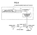
- Fig. 8 is a schematic diagram of a Raman amplifier according to a fourth embodiment of the present invention;
- Fig. 9 is a characteristic diagram that illustrates the relation between a polarization mode dispersion ⁇ and a degree of polarization effected by the polarization dispersion device in the pump light source (non-polarized light source) shown in Fig.
- Fig. 10 is a schematic diagram of a Raman amplifier according to a fifth embodiment of the present invention
- Fig. 11 is a schematic diagram of a non-polarized light source according to a sixth embodiment of the present invention
- Fig. 12 is a schematic diagram of a Raman amplifier according to a seventh embodiment of the present invention
- Fig. 13 is a schematic diagram of a Raman amplifier according to an eighth embodiment of the present invention
- Fig. 14 is a schematic diagram of a Raman amplifier according to a ninth embodiment of the present invention
- Fig. 15 is a schematic diagram of a Raman amplifier according to a tenth embodiment of the present invention
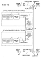
- Fig. 16 is a schematic diagram of a Raman amplifier according to an eleventh embodiment of the present invention
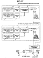
- Fig. 17 is a schematic diagram of a Raman amplifier according to a twelfth embodiment of the present invention.
- the interval ⁇ is equivalent to a vertical mode interval of a semiconductor laser device.
- the laser light source 1 may be the Fabry-Perot-type semiconductor laser device.
- Fig. 4 is a spectrum of a light beam output from a semiconductor laser module that includes a wavelength stabilizing fiber grating and forms an external resonator.
- This semiconductor laser module is typically used in the Raman amplification of a light signal that has a wavelength in the range of 1.55 ⁇ m.
- x and y represent two orthogonal axes that are inclined at 45° with respect to the axis of linear polarization
- E x (t) and Ey(t) represent the electric field intensity of the respective axis components
- j represents an imaginary unit
- E 0 represents the electric field intensity of the central angular frequency
- ⁇ + k and ⁇ - k represent the initial phases of the respective components.
- the polarization dispersion device 3 When the mode interval angular frequency of the light beam is considered to be ⁇ , the polarization dispersion device 3 effects a polarization mode dispersion ⁇ on the light beam that is not in the vicinity of (2 ⁇ / ⁇ ) and generates a time lag equivalent to the polarization mode dispersion ⁇ between the two polarization components.
- the polarization mode dispersion ⁇ is determined as follows.
- the electrical field intensity of the transmitted light beam 102 which has been effected with the polarization mode dispersion ⁇ by the polarization dispersion device 3 can be expressed as E x (t) and E y (t+ ⁇ ).
- S 0 , S 1 , S 2 , and S 3 represent the Stokes parameters that represent the polarization condition and are respectively determined by the inequalities (4), (5), (6), and (7), where ⁇ ... > represents a time average while E x * and Ey* represent the complex conjugate.
- the polarization mode dispersion ⁇ effected by the polarization dispersion device 3 is set such that the degree of polarization (DOP) obtained with the equality (8) is less.
- DOP degree of polarization
- Fig. 5 is a characteristic diagram that illustrates the relation between a polarization mode dispersion ⁇ effected by the polarization dispersion device and a degree of polarization.
- the horizontal axis represents the polarization mode dispersion (PMD) ⁇ (unit: ps) and the vertical axis represents the degree of polarization (unit: db).
- the curve 21 represents DOP calculated (hereafter, "calculated values) using the equality (8), when the spectral of the light beam output from the laser light source 1 satisfies the equality (1).
- the boxes represent DOP measured (hereafter, "measured values).
- the measured values and the calculated values show a peak near the polarization mode dispersion ⁇ of 30 ps. This indicates that the coherence of the light of the vertical mode is not lost.
- the polarization mode dispersion ⁇ which effects the optical path difference corresponding to a coherence length of about 2 cm having the vertical mode of the full width at half maximum of 10 GHz, is 100 ps. However, even if the polarization mode dispersion ⁇ is much less than 100 ps, the calculated values can be reduced by selecting appropriate conditions, that is to say polarization can be eliminated. Moreover, the polarization can be eliminated when the polarization mode dispersion ⁇ is in the range of 10 ps to 20 ps. This range is equivalent to a polarization maintaining fiber of the length of at the most 20 m. However, this length is small enough to be used practically so that the amount of light loss in the polarization maintaining fiber or the cost and the implementation capacity do not pose any major problem.
- Fig. 6 is a schematic diagram of the Raman amplifier according to a second embodiment of the present invention.
- a signal light is carried through an optical fiber 7, which is a Raman-amplifying medium, from an input terminal 61 towards an output terminal 62.
- a combiner 6 is provided between the terminals 61 and 62 on the optical fiber 7. This combiner 6 injects a pump light, which is a Raman pump light, transmitted from a non-polarized pump light source 5 into the optical fiber 7 in a direction opposite to the direction of propagation of the light signal.
- the non-polarized pump light source 5 has the configuration shown in Fig.1 .
- the combiner 6 may be an optical fiber fused type WDM coupler, which is formed by using the difference between the wavelengths of the light signal and the pump light, or a filter, which uses a dielectric coat.
- Fig. 7 is a schematic diagram of the Raman amplifier according to a third embodiment of the present invention.
- the parts in Fig. 7 that have same or similar configuration or that perform same or similar functions to those in Fig. 6 are assigned with the same reference numerals.
- the Raman amplifier according to the third embodiment includes a non-polarized pump light source 51 instead of the non-polarized pump light source 5 shown in Fig. 6 .
- the non-polarized pump light source 51 includes a Fabry-Perot-type semiconductor laser device 11 as laser light source. Even in this Raman amplifier the polarization-dependency of the Raman gain in the optical fiber 7 can be reduced.
- Fig. 8 is a schematic diagram of the Raman amplifier according to a fourth embodiment of the present invention.
- the parts in Fig. 8 that have same or similar configuration or that perform same or similar functions to those in Fig. 7 are assigned with the same reference numerals.
- the Raman amplifier according to the fourth embodiment includes a non-polarized pump light source 52 instead of the non-polarized pump light source 51 shown in Fig. 7 .
- This non-polarized pump light source 52 includes a reflector 12 that is provided between the Fabry-Perot-type semiconductor laser device 11 and the polarization dispersion device 3.
- the reflector 12 wavelength-selectively reflects a portion of the light beam output from the Fabry-Perot-type semiconductor laser device 11 to thereby form an external resonator along with the Fabry-Perot-type semiconductor laser device 11.
- the reflection wavelength, which is stable, of the reflector 12 can be set as the oscillation wavelength of the Fabry-Perot-type semiconductor laser device 11.
- the effects of the variation in the temperature and other driving conditions on the central wavelength of the Fabry-Perot-type semiconductor laser device 11 can be reduced.
- the Raman amplifier according to the fourth embodiment additionally requires the reflector 12, the desired effect can be achieved.
- the reflector 12 may be a fiber grating.
- Fig. 4 illustrates the spectrum when the reflector 12 is the fiber grating.
- the reflector 12 may be an etalon filter or a grating of a bulk component, etc.
- Fig. 9 is a characteristic diagram that illustrates the relation between the polarization mode dispersion ⁇ and the degree of polarization effected by the polarization dispersion device 3 in the non-polarized pump light source 52 shown in Fig. 8 , and the polarization-dependent gain (PDG) of the Raman gain.
- the horizontal axis represents the PMD (unit: ps) and the vertical axes represent the PDG and the DOP (unit: db).
- the curve 22 is a plot of the calculated values of the DOP determined from the equality (8), when the spectral form of the transmitted light beam of the Fabry-Perot-type semiconductor laser device 11 satisfies the equality (1).
- the boxes represent the measured values of the DOP.
- the solid triangles represent the measured values of the PDG of the Raman gain.
- the measured values and the calculated values show a peak near the polarization mode dispersion ⁇ of 30 ps. Consequently, in the non-polarized pump light source 52, by properly setting the polarization mode dispersion ⁇ effected by the polarization dispersion device 3 in the range of the optical path difference that is smaller than the coherence length of the non-polarized pump light source 52, the polarization of the pump light can be eliminated. As a result, the polarization-dependency of the Raman gain can be reduced.
- the fourth embodiment similar to the second and third embodiments, polarization-dependency of the Raman gain in the optical fiber 7 can be reduced as the non-polarized pump light is used.
- the stable reflection wavelength of the reflector 12 can be set as the oscillation wavelength of the Fabry-Perot-type semiconductor laser device 11.
- the effect of the variation in the temperature and other driving conditions on the central wavelength of the Fabry-Perot-type semiconductor laser device 11 can be reduced.
- polarization dispersion device 3 As the polarization dispersion device 3, a structure that separates the two polarization components and actually effects the optical path difference may be used. Alternatively, a polarization maintaining fiber or a crystal that has a birefringence characteristic may be used.
- Fig. 10 is a schematic diagram of the Raman amplifier according to a fifth embodiment of the present invention.
- the parts in Fig. 10 that have same or similar configuration or that perform same or similar functions to those in Fig. 8 are assigned with the same reference numerals.
- the Raman amplifier according to the fifth embodiment includes a non-polarized pump light source 53 instead of the non-polarized pump light source 52 shown in Fig. 8 . Moreover, this Raman amplifier includes a polarization maintaining fiber 31 instead of the polarization dispersion device 3 shown in Fig. 8 .
- the polarization dispersion of about 1 meter of the polarization maintaining fiber 31 is about 1.4 ps and a fiber length of 10 meters can effect a polarization dispersion of about 14 ps. Consequently, according to the fifth embodiment, a polarization-independent Raman amplifier can be realized that is practical in terms of compactness, stable operation, and reliability.
- Fig. 11 is a schematic diagram of the non-polarized light source according to a sixth embodiment of the present invention.
- the parts in Fig. 11 that have same or similar configuration or that perform same or similar functions to those in Fig. 1 are assigned with the same reference numerals.
- the non-polarized light source according to the sixth embodiment includes a laser light source 1' and a polarization combiner 4 in addition to structure shown in Fig. 1 .
- the polarization combiner 4 polarization-combines the light beam output from the laser light sources 1 and 1'.
- the output lights, which are mutually orthogonal, of the polarization combiner 4 are input into the polarization dispersion device 3.
- an incident angle of the light beams from both the laser light sources with respect to the polarization dispersion device 3 can be set as the polarization angle 105 at 45° (see Fig. 2 ).
- the transmitted light beams of both the laser light sources 1 and 1' can be simultaneously non-polarizing if the polarization mode dispersion effected by the polarization dispersion device 3 is set such that the degree of polarization (DOP) is reduced in the equality (8).
- the two laser light sources 1 and 1' may have a different central wavelength. Even in that case, the transmitted light beam of both the laser light sources 1 and 1' can be non-polarizing. Moreover, even if there is a large difference in the intensity of the transmitted light beam of the two laser light sources 1 and 1', non-polarization can be carried out. If during the operation, one of the two laser light sources 1 and 1' fails, then only the output decreases and deterioration of the degree of polarization is avoided. In this case, a backup laser light source, which is provided in case of a failure, is used as a cold standby.
- Fig. 12 is a schematic diagram of the Raman amplifier according to a seventh embodiment of the present invention.
- a signal light is carried through an optical fiber 7, which is a Raman-amplifying medium, from an input terminal 61 towards an output terminal 62.
- a combiner 6 is provided between the terminals 61 and 62 on the optical fiber 7. This combiner 6 injects a pump light, which is a Raman pump light, transmitted from a non-polarized pump light source 54 into the optical fiber 7 in a direction opposite to the direction of propagation of the light signal.
- the non-polarized pump light source 54 has the configuration shown in Fig. 11 .
- the combiner 6 may be an optical fiber fused type WDM coupler, which is formed by using the difference between the wavelengths of the light signal and the pump light, or a filter, which uses a dielectric coat.
- the non-polarized pump light source 54 can pump the light in two wavelengths. Even if only one of the light sources emits the light and the operation is carried out when the intensity of the pump light that contributes to the Raman amplification is low, the polarization-dependency of the Raman gain can be maintained at a reduced level, as the degree of polarization (DOP) of the pump light is less.
- DOP degree of polarization
- Fig. 13 is a schematic diagram of the Raman amplifier according to an eighth embodiment of the present invention.
- the parts in Fig. 13 that have same or similar configuration or that perform same or similar functions to those in Fig. 12 are assigned with the same reference numerals.
- the Raman amplifier according to the eighth embodiment includes a non-polarized pump light source 55 instead of the non-polarized pump light source 54 shown in Fig. 12 .
- the non-polarized pump light source 55 includes Fabry-Perot-type semiconductor lasers 11 and 13 as laser light sources. Even in this Raman amplifier the polarization-dependency of the Raman gain in the optical fiber 7 can be reduced.
- Fig. 14 is a schematic diagram of the Raman amplifier according to a ninth embodiment of the present invention.
- the Raman amplifier according to the ninth embodiment includes a non-polarized pump light source 56 instead of the non-polarized pump light source 55 shown in Fig. 12 .
- the non-polarized pump light source 56 includes reflectors 12 and 14 and a polarization combiner 4 in addition to the structure shown in Fig. 13 .
- the reflectors 12 and 14 wavelength-selectively reflect a portion of the transmitted light beam of the Fabry-Perot-type semiconductor laser devices 11 and 13 and form an external resonator along with the Fabry-Perot-type semiconductor laser devices 11 and 13.
- the stable reflection wavelength of the reflectors 12 and 14 can be set as the oscillation wavelength of the Fabry-Perot-type semiconductor laser devices 11 and 13.
- the effects of the variation in the temperature and other driving conditions on the central wavelength of the Fabry-Perot-type semiconductor laser devices 11 and 13 can be reduced. This more than compensates for the demerit of increasing the number of parts. Consequently, according the ninth embodiment, a stable Raman amplifier with low polarization-dependency can be obtained.
- Fig. 15 is a schematic diagram of the Raman amplifier according to a tenth embodiment of the present invention.
- the parts in Fig. 15 that have same or similar configuration or that perform same or similar functions to those in Fig. 14 are assigned with the same reference numerals.
- the Raman amplifier according to the tenth embodiment includes a non-polarized pump light source 57 instead of the non-polarized pump light source 56 shown in Fig. 14 .
- a polarization maintaining fiber 31 is provided in the non-polarized pump light source 57 instead of the polarization dispersion device 3 in the non-polarized pump light source 56 shown in Fig. 14 .
- the polarization dispersion of about 1 meter is about 1.4 ps and a fiber length of 10 meters can effect a polarization dispersion of about 14 ps. Consequently, according to the tenth embodiment, as in the fifth embodiment, a polarization-independent Raman amplifier can be achieved that is practical in terms of compactness, stable operation, and reliability.
- Fig. 16 is a schematic diagram of the Raman amplifier according to an eleventh embodiment of the present invention.
- the parts in Fig. 16 that have same or similar configuration or that perform same or similar functions to those in Fig. 10 are assigned with the same reference numerals.
- the Raman amplifier according to the eleventh embodiment includes two Raman amplifiers having a structure that is same as that shown in Fig. 10 .
- Non-polarized pump light sources 58 and 58' have a structure that is same as that of the non-polarized light source 53 shown in Fig. 10 .
- the non-polarized pump light source 58 includes the Fabry-Perot-type semiconductor laser device 11, the reflector 12, and the polarization maintaining fiber 31.
- the non-polarized pump light source 58' comprises a Fabry-Perot-type semiconductor laser device 13, a reflector 14, a node 2', and a polarization maintaining fiber 31'.
- two optical fibers 7 and 7' that are Raman-amplifying media and a 3 dB coupler 8 are provided.
- the transmitted light beams of the two non-polarized pump light sources 58 and 58' are combined once in the 3 dB coupler 8.
- One of the transmitted light beams from the 3 dB coupler 8 is input into the optical fiber 7 via the combiner 6 in a direction opposite to the propagation direction (from the input end 61 towards the output end 62) of the light signal, thus forming a first Raman amplifier.
- the other transmitted light beam from the 3 dB coupler 8 is input into the optical fiber 7' via a combiner 6' in a direction opposite to the propagation direction (from an input end 61' towards an output end 62') of the light signal, thus forming a second Raman amplifier.
- the transmitted light beam of the other Fabry-Perot-type semiconductor laser device is equally supplied to the two optical fibers 7 and 7'. Hence, deterioration in the pump light due to the failure can be checked and the reliability of the Raman amplifier can be improved.
- Fig. 17 is a schematic diagram of the Raman amplifier according to a twelfth embodiment of the present invention.
- the parts in Fig. 17 that are identical or equivalent to those in Fig. 15 are assigned the same reference numerals.
- a variation of the Raman amplifier according to the tenth embodiment ( Fig. 15 ) is disclosed in the Raman amplifier according to the twelfth embodiment of the present invention.
- non-polarized pump light sources 59 and 59' have an identical structure to the non-polarized pump light source 57 according to the tenth embodiment ( Fig. 15 ) of the present invention.
- the non-polarized pump light source 59 comprises Fabry-Perot-type semiconductor laser devices 11 and 13, reflectors 12 and 14, and a polarization maintaining fiber 31.
- the non-polarized pump light source 59' comprises Fabry-Perot-type semiconductor laser devices 15 and 17, reflectors 16 and 18, and a polarization maintaining fiber 31'.
- the transmitted light beams of the non-polarized pump light sources 59 and 59' have different central wavelengths.
- a wavelength combiner 9 is provided.
- the transmitted light beams of the non-polarized pump light sources 59 and 59' are wavelength-combined in the wavelength combiner 9 and input into the optical fiber 7 via the combiner 6 in a direction opposite to the propagation direction of the light signal and thus forming a Raman amplifier.
- a pump light of four different wavelengths can be used.
- the laser device and the other optical parts that constitute a pump light source are connected using optical fibers.
- the connecting medium need not necessarily be limited to optical fibers. The same results can be achieved with any medium that can carry light signals.
- a laser light source transmits a virtually linearly-polarized light beam that has plural mode components arranged at an interval of an almost equal angular frequency.
- a polarization dispersion device is connected to the laser light source in such a way that the polarization axis of the polarization dispersion device meets the polarization axis of the light beam output from the laser light source to form a 45° angle.
- the polarization dispersion device effects on the light beam output from the laser light source a polarization mode dispersion that is not in the vicinity of (2 ⁇ / ⁇ ), where ⁇ is the mode interval angular frequency.
- a laser light source transmits a virtually linearly-polarized light beam that has plural mode components arranged at an interval of an almost equal angular frequency.
- a polarization dispersion device is connected to the laser light source in such a way that the polarization axis of the polarization dispersion device meets the polarization axis of the light beam output from the laser light source to form a 45° angle.
- a Fabry-Perot-type semiconductor laser device is used in the laser light source.
- a reflector is provided between the Fabry-Perot-type semiconductor laser device and the polarization dispersion device.
- the reflector selectively reflects a portion of the transmitted light beam of the Fabry-Perot-type semiconductor laser device and forms an external resonator.
- a polarization maintaining fiber is used instead of the polarization dispersion device.
- two laser light sources transmit a virtually linearly-polarized light beams that has plural mode components arranged at an interval of an almost equal angular frequency.
- a polarization dispersion device is connected to a polarization combining unit in such a way that the polarization axis of the polarization dispersion device meets the polarization axis of transmitted light beam of the laser light source to form a 45° angle.
- DOP degree of polarization
- the two laser light sources are a Fabry-Perot-type semiconductor laser devices.
- each reflector selectively reflects a portion of the transmitted light beam of the respective Fabry-Perot-type semiconductor laser device and forms an external resonator.
- a polarization maintaining fiber is used instead of the polarization dispersion device.
- the non-polarized light source according to any one of the above inventions is used to generate a pump light in a wavelength band that effects the Raman gain on a light signal.
- the pump light is input into an optical fiber, which is a Raman-amplifying medium, by means of an injection unit.
- an optical fiber which is a Raman-amplifying medium
- a first non-polarized light source and a second non-polarizing light are used to generate a pump light in a wavelength band that effects the Raman gain on the respective light signal.
- the transmitted light beam of the first non-polarized light source is input into a first optical fiber, which is a Raman-amplifying medium, by means of a first injection unit.
- the transmitted light beam of the second non-polarized light source is input into a second optical fiber, which is a Raman-amplifying medium, by means of a second injection unit.
- two Raman amplifiers are fabricated.
- the pump light is equally supplied to both the Raman amplifiers from the other non-polarized light source.
- deterioration in the pump light owing to the failure can be checked and the reliability of the Raman amplifier can be improved.
- plural non-polarized light sources are used to generate pump lights having varying central wavelengths in a wavelength band that effects a Raman gain on a light signal.
- the transmitted light beam of the plural non-polarized light sources having varying wavelengths is wavelength-combined in a wavelength-combining and injection unit and input into an optical fiber, which is a Raman-amplifying medium.
- the non-polarized light source and the Raman amplifier according to the present invention are effective in an optical transmission system, especially suitable in an apparatus aimed at reducing the polarization-dependency of the Raman gain in an optical fiber.
Landscapes
- Physics & Mathematics (AREA)
- Electromagnetism (AREA)
- Engineering & Computer Science (AREA)
- Plasma & Fusion (AREA)
- Optics & Photonics (AREA)
- Optical Modulation, Optical Deflection, Nonlinear Optics, Optical Demodulation, Optical Logic Elements (AREA)
- Lasers (AREA)
- Semiconductor Lasers (AREA)
Abstract
Claims (11)
- Source de lumière non polarisée comprenant :une source de lumière laser à semi-conducteur (1) qui émet un faisceau de lumière polarisé de manière linéaire (101), le faisceau de lumière polarisé de manière linéaire présentant plusieurs composantes de mode de polarisation disposées à une pulsation d'intervalle de mode Δω, la pulsation d'intervalle de mode étant une pulsation d'intervalle entre des composantes de mode de polarisation adjacentes ; etun dispositif de dispersion de polarisation (3) qui est connecté à la source de lumière laser (1) de telle façon qu'un axe de polarisation (104) du dispositif de dispersion de polarisation (3) forme un angle de 45 degrés par rapport à un axe de polarisation (103) du faisceau de lumière émis par la source de lumière laser (1) ;dans lequel le dispositif de dispersion de polarisation (3) est adapté pour effectuer sur le faisceau de lumière polarisé de manière linéaire (101) émis par la source de lumière laser, une dispersion de mode de polarisation τ qui ne se situe pas à moins de (2π / Δω), de telle sorte que le degré de polarisation soit inférieur à 0,5, grâce à quoi la différence de chemin optique entre des composantes de mode de polarisation adjacentes est inférieure à la longueur de cohérence, la longueur de cohérence correspondant à la largeur à mi-hauteur d'une enveloppe spectrale optique du faisceau de lumière polarisé de manière linéaire, ou à la largeur à mi-hauteur d'un mode vertical du laser à semi-conducteur de la source de lumière laser.
- Source de lumière non polarisée selon la revendication 1, caractérisée en ce que le degré de polarisation, DOP, est déterminé par l'égalité :

A(ω') étant une fonction de forme spectrale et ω' ω = ωc, où ω' est une pulsation relative, ω est une pulsation d'une composante de mode de polarisation du faisceau de lumière, et ωcest une pulsation centrale du faisceau de lumière. - Source de lumière non polarisée selon la revendication 1 ou 2, caractérisée en ce que le dispositif de dispersion de polarisation est une fibre de maintien de polarisation (31).
- Source de lumière non polarisée selon l'une quelconque des revendications 1 à 3, comprenant en outre un réflecteur (12) disposé entre la source de lumière laser (1) et le dispositif de dispersion de polarisation (3), dans laquelle le réflecteur (12) réfléchit de manière sélective une partie du faisceau de lumière délivré en sortie par la source de lumière laser (1) et forme un résonateur extérieur.
- Source de lumière non polarisée selon l'une quelconque des revendications 1 à 4, dans laquelle la source de lumière laser (1) est un dispositif laser à semi-conducteur du type Fabry-Perot (11).
- Source de lumière non polarisée selon l'une quelconque des revendications 1 à 3, comprenant :ladite source de lumière laser en tant que première source de lumière laser (1) qui délivre en sortie un premier faisceau de lumière polarisé de manière linéaire et une seconde source de lumière laser (1') qui délivre en sortie un second faisceau de lumière polarisé de manière linéaire, le premier faisceau de lumière et le second faisceau de lumière présentant plusieurs composantes de mode disposées à un intervalle d'une pulsation presque égale ;une unité de combinaison de polarisation (4) qui combine en polarisation le premier faisceau de lumière et le second faisceau de lumière; etdans laquelle le dispositif de dispersion de polarisation est connecté à l'unité de combinaison de polarisation (4) de telle sorte qu'un axe de polarisation du dispositif de dispersion de polarisation (3) forme un angle de 45° par rapport à un axe de polarisation du faisceau de lumière délivré en sortie par l'unité de combinaison de polarisation (4) au lieu du faisceau de lumière délivré en sortie par la première source de lumière laser ;grâce à quoi, même lorsque la différence de chemin optique entre les deux modes de polarisation du faisceau de lumière est inférieure à une longueur de cohérence du faisceau de lumière, il est possible d'obtenir un faisceau de lumière qui n'est pas polarisé.
- Source de lumière non polarisée selon la revendication 6, comprenant en outre :un premier réflecteur (12) qui est disposé entre la première source de lumière laser (1) et l'unité de combinaison de polarisation (4), dans laquelle le premier réflecteur (12) réfléchit de manière sélective une partie du faisceau de lumière délivré en sortie par la première source de lumière laser (1) et forme un résonateur extérieur ; etun second réflecteur (14) qui est disposé entre la seconde source de lumière laser (1') et l'unité de combinaison de polarisation (4), dans laquelle le second réflecteur (14) réfléchit de manière sélective une partie du faisceau de lumière délivré en sortie par la seconde source de lumière laser (1') et forme un résonateur extérieur.
- Source de lumière non polarisée selon l'une quelconque des revendications 6 à 7, dans laquelle la première source de lumière laser (1) et la seconde source de lumière laser (1') sont des dispositifs lasers à semi-conducteur du type Fabry-Perot.
- Amplificateur Raman comprenant :une fibre optique (7) qui est un milieu d'amplification Raman et qui achemine un signal de lumière ;une source de lumière non polarisée (54) selon l'une quelconque des revendications 1 à 8, qui génère une lumière de pompe dans une bande de longueur d'onde qui réalise un gain Raman sur le signal de lumière ; etune unité d'injection qui injecte la lumière de pompe dans la fibre optique (7).
- Amplificateur Raman comprenant :une première fibre optique (7) et une seconde fibre optique (7') qui sont des milieux d'amplification Raman et qui acheminent un premier signal de lumière et un second signal de lumière ;une première source de lumière non polarisée (58) selon l'une quelconque des revendications 1 à 8, qui délivre en sortie un premier faisceau de lumière et une seconde source de lumière non polarisée (58') selon l'une quelconque des revendications 1 à 8, qui délivre en sortie une second faisceau de lumière ;une unité de combinaison et de séparation (8) qui combine le premier faisceau de lumière et le second faisceau de lumière, et divise le faisceau de lumière combiné en un premier faisceau de lumière divisé et en un second faisceau de lumière divisé ; etune première unité d'injection (6) qui injecte dans la première fibre optique (7) le premier faisceau de lumière divisé ; etune seconde unité d'injection (6') qui injecte dans la seconde fibre optique (7') le second faisceau de lumière divisé.
- Amplificateur Raman comprenant :une fibre optique (7) qui est un milieu d'amplification Raman et qui achemine un signal de lumière ;une pluralité de sources de lumière non polarisées selon l'une quelconque des revendications 1 à 8, chacune d'elles générant une lumière de pompe qui présente une longueur d'onde centrale variable dans une bande de longueur d'onde qui réalise un gain Raman sur un signal de lumière ;une unité de combinaison de longueur d'onde et d'injection (9) qui combine en longueur d'onde les faisceaux de pompe délivrés en sortie par les sources de lumière non polarisées, et qui injecte les lumières de pompe dans la fibre optique (7).
Applications Claiming Priority (3)
| Application Number | Priority Date | Filing Date | Title |
|---|---|---|---|
| JP2002002453 | 2002-01-30 | ||
| JP2002022453A JP2003224327A (ja) | 2002-01-30 | 2002-01-30 | 無偏光光源装置およびラマン増幅器 |
| PCT/JP2003/000729 WO2003065522A1 (fr) | 2002-01-30 | 2003-01-27 | Dispositif de source lumineuse non polarisante et amplificateur raman |
Publications (3)
| Publication Number | Publication Date |
|---|---|
| EP1437808A1 EP1437808A1 (fr) | 2004-07-14 |
| EP1437808A4 EP1437808A4 (fr) | 2005-10-05 |
| EP1437808B1 true EP1437808B1 (fr) | 2012-07-04 |
Family
ID=27654423
Family Applications (1)
| Application Number | Title | Priority Date | Filing Date |
|---|---|---|---|
| EP03701883A Expired - Lifetime EP1437808B1 (fr) | 2002-01-30 | 2003-01-27 | Dispositif de source lumineuse non polarisee et amplificateur raman |
Country Status (5)
| Country | Link |
|---|---|
| US (1) | US7218441B2 (fr) |
| EP (1) | EP1437808B1 (fr) |
| JP (1) | JP2003224327A (fr) |
| CN (1) | CN1305188C (fr) |
| WO (1) | WO2003065522A1 (fr) |
Families Citing this family (18)
| Publication number | Priority date | Publication date | Assignee | Title |
|---|---|---|---|---|
| US7095930B2 (en) * | 2003-07-17 | 2006-08-22 | Draka Comteq B.V. | Groove cable |
| US7499159B2 (en) * | 2004-04-16 | 2009-03-03 | Ahura Corporation | Method and apparatus for conducting Raman spectroscopy using a remote optical probe |
| WO2006016913A2 (fr) * | 2004-04-30 | 2006-02-16 | Ahura Corporation | Procede et appareil permettant d'effectuer une spectroscopie raman |
| US7548311B2 (en) | 2005-04-29 | 2009-06-16 | Ahura Corporation | Method and apparatus for conducting Raman spectroscopy |
| US7289208B2 (en) * | 2004-08-30 | 2007-10-30 | Ahura Corporation | Low profile spectrometer and Raman analyzer utilizing the same |
| US20060088069A1 (en) * | 2004-08-30 | 2006-04-27 | Daryoosh Vakhshoori | Uncooled, low profile, external cavity wavelength stabilized laser, and portable Raman analyzer utilizing the same |
| US20060045151A1 (en) * | 2004-08-30 | 2006-03-02 | Daryoosh Vakhshoori | External cavity wavelength stabilized Raman lasers insensitive to temperature and/or external mechanical stresses, and Raman analyzer utilizing the same |
| US20060170917A1 (en) * | 2004-08-30 | 2006-08-03 | Daryoosh Vakhshoori | Use of free-space coupling between laser assembly, optical probe head assembly, spectrometer assembly and/or other optical elements for portable optical applications such as Raman instruments |
| US7773645B2 (en) * | 2005-11-08 | 2010-08-10 | Ahura Scientific Inc. | Uncooled external cavity laser operating over an extended temperature range |
| US7701571B2 (en) * | 2006-08-22 | 2010-04-20 | Ahura Scientific Inc. | Raman spectrometry assembly |
| US8208503B2 (en) | 2010-05-26 | 2012-06-26 | Honeywell International Inc. | Fiber light source with high mean wavelength stability and reliability |
| US9250355B2 (en) * | 2011-04-06 | 2016-02-02 | Futurwei Technologies, Inc. | Device and method for optical beam combination |
| US9025241B2 (en) * | 2011-10-14 | 2015-05-05 | Kotura, Inc. | Gain medium providing laser and amplifier functionality to optical device |
| KR20200097289A (ko) | 2017-12-10 | 2020-08-18 | 루머스 리미티드 | 이미지 프로젝터 |
| KR102651647B1 (ko) | 2019-03-12 | 2024-03-26 | 루머스 리미티드 | 이미지 프로젝터 |
| KR20220060549A (ko) * | 2019-09-30 | 2022-05-11 | 오스람 옵토 세미컨덕터스 게엠베하 | 레이저 패키지 및 레이저 패키지들을 갖는 시스템 |
| CN115176458B (zh) | 2020-04-20 | 2024-06-07 | 鲁姆斯有限公司 | 具有增强的激光效率和眼睛安全的近眼显示器 |
| WO2022130393A1 (fr) | 2020-12-20 | 2022-06-23 | Lumus Ltd. | Projecteur d'image avec balayage laser sur modulateur de lumière spatial |
Family Cites Families (21)
| Publication number | Priority date | Publication date | Assignee | Title |
|---|---|---|---|---|
| US3728644A (en) * | 1971-11-01 | 1973-04-17 | Bell Telephone Labor Inc | Polarization transformation apparatus |
| US3728643A (en) * | 1971-11-01 | 1973-04-17 | Bell Telephone Labor Inc | Apparatus for transforming nonorthogonal elliptically polarized waves into orthogonal linearly polarized waves |
| US4042302A (en) * | 1976-03-10 | 1977-08-16 | Westinghouse Electric Corporation | Broadband wavelength discriminator |
| JPS59155806A (ja) * | 1983-02-24 | 1984-09-05 | Kokusai Denshin Denwa Co Ltd <Kdd> | 無偏光素子 |
| US4556293A (en) * | 1983-05-02 | 1985-12-03 | The United States Of America As Represented By The Secretary Of The Navy | Broadband unpolarized light source |
| JPH063622A (ja) * | 1992-06-19 | 1994-01-14 | Mitsubishi Gas Chem Co Inc | 偏波無依存型光アイソレータ |
| DE4222658C1 (fr) * | 1992-07-10 | 1993-07-22 | Messerschmitt-Boelkow-Blohm Ag, 8012 Ottobrunn, De | |
| TW312744B (fr) * | 1994-10-11 | 1997-08-11 | Adoban Tesuto Kk | |
| JPH08254668A (ja) | 1995-03-17 | 1996-10-01 | Fujitsu Ltd | レーザ・ダイオード・モジュール及びデポラライザ |
| JPH09326758A (ja) * | 1996-06-04 | 1997-12-16 | Nippon Telegr & Teleph Corp <Ntt> | 短パルス光を用いた無偏光送信方法および装置 |
| US5881185A (en) * | 1996-08-19 | 1999-03-09 | Honeywell Inc. | Method and apparatus for accurately fabricating a depolarizer |
| JP2000151507A (ja) | 1998-11-09 | 2000-05-30 | Nippon Telegr & Teleph Corp <Ntt> | 光伝送システム |
| JP2001147454A (ja) | 1999-09-06 | 2001-05-29 | Furukawa Electric Co Ltd:The | ラマン光増幅装置 |
| US6760151B1 (en) * | 2000-04-27 | 2004-07-06 | Jds Uniphase Corporation | Depolarized semiconductor laser sources |
| JP2002031735A (ja) | 2000-05-12 | 2002-01-31 | Furukawa Electric Co Ltd:The | 波長合波モジュール |
| JP2001356377A (ja) * | 2000-06-16 | 2001-12-26 | Kdd Submarine Cable Systems Inc | ポンプ光発生装置及びファイバラマン増幅器 |
| JP4306112B2 (ja) * | 2000-10-12 | 2009-07-29 | 三菱電機株式会社 | ラマン増幅器 |
| US6522796B1 (en) * | 2000-10-24 | 2003-02-18 | Jds Uniphase Corporation | Depolarizing polarization mode combiner |
| JP3857881B2 (ja) * | 2001-01-31 | 2006-12-13 | 古河電気工業株式会社 | ラマン光増幅用励起光源装置およびそれを用いたラマン光増幅システム |
| CN1568565B (zh) | 2001-10-10 | 2010-11-10 | 古河电气工业株式会社 | 非偏振光化激光二极管模块及非偏振光化激光二极管光源 |
| US6972842B2 (en) * | 2003-08-25 | 2005-12-06 | Lucent Technologies Inc. | Monitoring alignment between pulse carvers and phase modulators in optical systems |
-
2002
- 2002-01-30 JP JP2002022453A patent/JP2003224327A/ja active Pending
-
2003
- 2003-01-27 WO PCT/JP2003/000729 patent/WO2003065522A1/fr not_active Ceased
- 2003-01-27 CN CNB038009609A patent/CN1305188C/zh not_active Expired - Lifetime
- 2003-01-27 EP EP03701883A patent/EP1437808B1/fr not_active Expired - Lifetime
- 2003-01-27 US US10/482,223 patent/US7218441B2/en not_active Expired - Lifetime
Non-Patent Citations (2)
| Title |
|---|
| BROSSEAU; BARAKAT: "Jones and Mueller polarization matrices for random media", OPTICS COMMUNICATIONS, vol. 84, no. 3-4, 15 July 1991 (1991-07-15), pages 127 - 132, XP022564706 * |
| SVELTO O.: "Principles of Lasers, 4th Edition", PLENUM PRESS, pages: 505 - 505 * |
Also Published As
| Publication number | Publication date |
|---|---|
| JP2003224327A (ja) | 2003-08-08 |
| EP1437808A4 (fr) | 2005-10-05 |
| US7218441B2 (en) | 2007-05-15 |
| US20040165254A1 (en) | 2004-08-26 |
| EP1437808A1 (fr) | 2004-07-14 |
| CN1552116A (zh) | 2004-12-01 |
| CN1305188C (zh) | 2007-03-14 |
| WO2003065522A1 (fr) | 2003-08-07 |
Similar Documents
| Publication | Publication Date | Title |
|---|---|---|
| EP1437808B1 (fr) | Dispositif de source lumineuse non polarisee et amplificateur raman | |
| US6970484B2 (en) | Laser tuning by spectrally dependent spatial filtering | |
| US5243610A (en) | Optical fiber dispersion-compensating device | |
| JP2695122B2 (ja) | 単一ポンプ光源を利用した波長可変形の多波長光繊維レーザー構図 | |
| CN100414793C (zh) | 光纤光栅稳定的半导体泵激源 | |
| US5949801A (en) | Tunable laser and method for operating the same | |
| US10530126B2 (en) | External cavity laser | |
| US7072369B2 (en) | Depolarized laser diode module and depolarized laser diode light source | |
| US6728437B2 (en) | Pumping light generator and fiber Raman amplifier | |
| US6501591B1 (en) | Tunable fiber optic parametric oscillator | |
| EP1130718A2 (fr) | Laser stabilisé à fréquence accordable à réseau à fibre | |
| US20020118715A1 (en) | Semiconductor laser module and Raman amplifier using the module | |
| EP1343227B1 (fr) | Génération de signaux électroniques porteurs dans le domaine optique | |
| US5760949A (en) | Light amplifier | |
| US20020171913A1 (en) | Method and apparatus for acheiving | |
| EP1394599B1 (fr) | Convertisseur de longueur d'onde | |
| US20030053064A1 (en) | Wavelength detector and optical transmitter | |
| US20080231861A1 (en) | Polarization Maintaining Optical Delay Circuit | |
| JP4809554B2 (ja) | 半導体レーザモジュール及びこれを用いたラマン増幅器 | |
| US12261405B2 (en) | Apparatus and method for spectrally shaping a laser beam | |
| JP2948221B1 (ja) | 波長可変光源装置 | |
| Xu et al. | Broadband tunable narrow-linewidth laser based on scattering-enhanced fiber covering ESCL bands | |
| WO2022270615A1 (fr) | Dispositif de source de lumière de sortie de fibre optique, et séparateur de faisceau polarisant réfléchissant à polarisation unique utilisé dans celui-ci | |
| Baribault et al. | Stitch-free widely tunable dual-channel fibre laser for use in a passive component analyser | |
| JP2975597B1 (ja) | 光制御型フェーズドアレーアンテナ装置 |
Legal Events
| Date | Code | Title | Description |
|---|---|---|---|
| PUAI | Public reference made under article 153(3) epc to a published international application that has entered the european phase |
Free format text: ORIGINAL CODE: 0009012 |
|
| 17P | Request for examination filed |
Effective date: 20040319 |
|
| AK | Designated contracting states |
Kind code of ref document: A1 Designated state(s): AT BE BG CH CY CZ DE DK EE ES FI FR GB GR HU IE IT LI LU MC NL PT SE SI SK TR |
|
| A4 | Supplementary search report drawn up and despatched |
Effective date: 20050822 |
|
| RIC1 | Information provided on ipc code assigned before grant |
Ipc: 7G 02F 1/01 B Ipc: 7H 01S 3/30 B Ipc: 7G 02F 1/35 B Ipc: 7H 01S 5/02 A |
|
| RAP1 | Party data changed (applicant data changed or rights of an application transferred) |
Owner name: MITSUBISHI DENKI KABUSHIKI KAISHA |
|
| 17Q | First examination report despatched |
Effective date: 20051213 |
|
| 17Q | First examination report despatched |
Effective date: 20051213 |
|
| GRAP | Despatch of communication of intention to grant a patent |
Free format text: ORIGINAL CODE: EPIDOSNIGR1 |
|
| RIC1 | Information provided on ipc code assigned before grant |
Ipc: H01S 3/30 20060101ALI20111201BHEP Ipc: H01S 3/094 20060101ALI20111201BHEP Ipc: H01S 3/067 20060101ALI20111201BHEP Ipc: H01S 5/02 20060101AFI20111201BHEP Ipc: G02F 1/35 20060101ALI20111201BHEP Ipc: G02F 1/01 20060101ALI20111201BHEP |
|
| RBV | Designated contracting states (corrected) |
Designated state(s): DE FR GB IT |
|
| RIN1 | Information on inventor provided before grant (corrected) |
Inventor name: KOGURE, TAICHI Inventor name: SUGIHARA, TAKASHI Inventor name: MOTOSHIMA, KUNIAKI Inventor name: TOKURA, TOSHIYUKI |
|
| GRAS | Grant fee paid |
Free format text: ORIGINAL CODE: EPIDOSNIGR3 |
|
| GRAA | (expected) grant |
Free format text: ORIGINAL CODE: 0009210 |
|
| AK | Designated contracting states |
Kind code of ref document: B1 Designated state(s): DE FR GB IT |
|
| REG | Reference to a national code |
Ref country code: GB Ref legal event code: FG4D |
|
| REG | Reference to a national code |
Ref country code: DE Ref legal event code: R096 Ref document number: 60341445 Country of ref document: DE Effective date: 20120823 |
|
| PLBE | No opposition filed within time limit |
Free format text: ORIGINAL CODE: 0009261 |
|
| STAA | Information on the status of an ep patent application or granted ep patent |
Free format text: STATUS: NO OPPOSITION FILED WITHIN TIME LIMIT |
|
| PG25 | Lapsed in a contracting state [announced via postgrant information from national office to epo] |
Ref country code: IT Free format text: LAPSE BECAUSE OF FAILURE TO SUBMIT A TRANSLATION OF THE DESCRIPTION OR TO PAY THE FEE WITHIN THE PRESCRIBED TIME-LIMIT Effective date: 20120704 |
|
| 26N | No opposition filed |
Effective date: 20130405 |
|
| REG | Reference to a national code |
Ref country code: DE Ref legal event code: R097 Ref document number: 60341445 Country of ref document: DE Effective date: 20130405 |
|
| GBPC | Gb: european patent ceased through non-payment of renewal fee |
Effective date: 20130127 |
|
| PG25 | Lapsed in a contracting state [announced via postgrant information from national office to epo] |
Ref country code: DE Free format text: LAPSE BECAUSE OF NON-PAYMENT OF DUE FEES Effective date: 20130801 |
|
| REG | Reference to a national code |
Ref country code: DE Ref legal event code: R119 Ref document number: 60341445 Country of ref document: DE Effective date: 20130801 |
|
| PG25 | Lapsed in a contracting state [announced via postgrant information from national office to epo] |
Ref country code: GB Free format text: LAPSE BECAUSE OF NON-PAYMENT OF DUE FEES Effective date: 20130127 |
|
| REG | Reference to a national code |
Ref country code: FR Ref legal event code: PLFP Year of fee payment: 14 |
|
| REG | Reference to a national code |
Ref country code: FR Ref legal event code: PLFP Year of fee payment: 15 |
|
| REG | Reference to a national code |
Ref country code: FR Ref legal event code: PLFP Year of fee payment: 16 |
|
| PGFP | Annual fee paid to national office [announced via postgrant information from national office to epo] |
Ref country code: FR Payment date: 20211217 Year of fee payment: 20 |