EP1438218B1 - Systeme d'airbag situe dans un vehicule, notamment une automobile - Google Patents
Systeme d'airbag situe dans un vehicule, notamment une automobile Download PDFInfo
- Publication number
- EP1438218B1 EP1438218B1 EP02762465A EP02762465A EP1438218B1 EP 1438218 B1 EP1438218 B1 EP 1438218B1 EP 02762465 A EP02762465 A EP 02762465A EP 02762465 A EP02762465 A EP 02762465A EP 1438218 B1 EP1438218 B1 EP 1438218B1
- Authority
- EP
- European Patent Office
- Prior art keywords
- airbag
- region
- instrument panel
- housing
- area
- Prior art date
- Legal status (The legal status is an assumption and is not a legal conclusion. Google has not performed a legal analysis and makes no representation as to the accuracy of the status listed.)
- Expired - Lifetime
Links
Images


Classifications
-
- B—PERFORMING OPERATIONS; TRANSPORTING
- B60—VEHICLES IN GENERAL
- B60R—VEHICLES, VEHICLE FITTINGS, OR VEHICLE PARTS, NOT OTHERWISE PROVIDED FOR
- B60R21/00—Arrangements or fittings on vehicles for protecting or preventing injuries to occupants or pedestrians in case of accidents or other traffic risks
- B60R21/02—Occupant safety arrangements or fittings, e.g. crash pads
- B60R21/16—Inflatable occupant restraints or confinements designed to inflate upon impact or impending impact, e.g. air bags
- B60R21/20—Arrangements for storing inflatable members in their non-use or deflated condition; Arrangement or mounting of air bag modules or components
- B60R21/205—Arrangements for storing inflatable members in their non-use or deflated condition; Arrangement or mounting of air bag modules or components in dashboards
-
- B—PERFORMING OPERATIONS; TRANSPORTING
- B60—VEHICLES IN GENERAL
- B60H—ARRANGEMENTS OF HEATING, COOLING, VENTILATING OR OTHER AIR-TREATING DEVICES SPECIALLY ADAPTED FOR PASSENGER OR GOODS SPACES OF VEHICLES
- B60H1/00—Heating, cooling or ventilating devices
- B60H1/00507—Details, e.g. mounting arrangements, desaeration devices
- B60H1/00514—Details of air conditioning housings
- B60H1/0055—Details of air conditioning housings the housing or parts thereof being integrated in other devices, e.g. dashboard
-
- B—PERFORMING OPERATIONS; TRANSPORTING
- B60—VEHICLES IN GENERAL
- B60R—VEHICLES, VEHICLE FITTINGS, OR VEHICLE PARTS, NOT OTHERWISE PROVIDED FOR
- B60R21/00—Arrangements or fittings on vehicles for protecting or preventing injuries to occupants or pedestrians in case of accidents or other traffic risks
- B60R21/02—Occupant safety arrangements or fittings, e.g. crash pads
- B60R21/04—Padded linings for the vehicle interior ; Energy absorbing structures associated with padded or non-padded linings
- B60R21/045—Padded linings for the vehicle interior ; Energy absorbing structures associated with padded or non-padded linings associated with the instrument panel or dashboard
-
- B—PERFORMING OPERATIONS; TRANSPORTING
- B60—VEHICLES IN GENERAL
- B60R—VEHICLES, VEHICLE FITTINGS, OR VEHICLE PARTS, NOT OTHERWISE PROVIDED FOR
- B60R21/00—Arrangements or fittings on vehicles for protecting or preventing injuries to occupants or pedestrians in case of accidents or other traffic risks
- B60R21/02—Occupant safety arrangements or fittings, e.g. crash pads
- B60R21/16—Inflatable occupant restraints or confinements designed to inflate upon impact or impending impact, e.g. air bags
- B60R21/20—Arrangements for storing inflatable members in their non-use or deflated condition; Arrangement or mounting of air bag modules or components
- B60R21/217—Inflation fluid source retainers, e.g. reaction canisters; Connection of bags, covers, diffusers or inflation fluid sources therewith or together
- B60R21/2171—Inflation fluid source retainers, e.g. reaction canisters; Connection of bags, covers, diffusers or inflation fluid sources therewith or together specially adapted for elongated cylindrical or bottle-like inflators with a symmetry axis perpendicular to the main direction of bag deployment, e.g. extruded reaction canisters
Definitions
- the invention relates to an airbag arrangement in a vehicle, in particular a Motor vehicle, according to the preamble of claim 1.
- An airbag arrangement in a motor vehicle is z. B. from DE 197 04 684 C2
- the airbag arrangement is designed here as a passenger airbag arrangement, in which the airbag together with associated gas generator, d. H. the entire airbag module, in one of the Windscreen facing away from the rear instrument panel area, the Passenger seat position is assigned directly, is arranged. This should in the case of Activation of the passenger airbag arrangement of the airbag quickly in front of itself in a normal Be seated pillion passenger inflated. Due to this arrangement of Airbags in the rear instrument panel area, the airbag here so immediately after his Activation immediately in the inflation area with high filling pressure of z. B. about 30 bar before Passenger inflated.
- the problem is such a structure in connection with not in a normal sitting position (out-of-position) vehicle occupants, z. Children, in the passenger area immediately behind the dashboard, or else Children and adults B. in one with the head towards the instrument panel located forward or inclined posture and / or may not be in accordance with regulations are belted.
- Next airbag assemblies are known to a module carrier of a motor vehicle, so z. B. from EP 1038 737 A2, in which an airbag module on a module carrier as a cross member is fixed.
- This module carrier runs as a vehicle cross member between the opposite A-pillars in a range approximately at the height of a heating and Air conditioner, in an area in front of the heating and air conditioning unit related to the Instrument panel seen in the vehicle longitudinal axis direction.
- Receiving portion formed in the airbag module are used and fixed there can.
- the brackets for the airbag module are here designed so that the airbag module must be rotated after insertion in the brackets to the airbag module in the correct use position to convict.
- EP 0 997 352 A1 and the US 5,209,519 a structure is known in each case in which an airbag outlet opening in the front Instrument panel wall area windshield close is formed.
- EP 0 997 352 A1 is to be avoided by a special airbag folding or unfolding, that the airbag comes into contact with the windshield.
- US 3,817,552 is intended allow easy pre-assembly of the system.
- the Inflation behavior of the airbag can be improved by using a special injection technique the fluttering of the airbag when inflating should be avoided. For example, this is done a gas flow directed towards the windshield upwards.
- US 5,209,519 on the other hand, the object is to provide an airbag housing available, the Can absorb impact energy and also has sufficient mechanical strength, d. H. that the airbag housing should have areas of different strength.
- a two-piece airbag housing provided.
- US Pat. No. 6,193,271 is included Design based, in which the airbag outlet opening in the potential impact area is arranged. The same would be the case, if the structure according to the DE 198 60 804 A1 would be transferred to a passenger area of an instrument panel.
- the object of the invention is an airbag assembly on an instrument panel of a Vehicle, in particular a motor vehicle to create, with the aggressiveness of Inflating airbags against vehicle occupants, in particular of himself Passenger area out-of-position vehicle occupants, be significantly reduced can.
- the front instrument panel wall area Airbag outlet opening a predetermined safety distance to a potential Head impact area of a vehicle occupant in a away from the windshield towards the vehicle interior to the front instrument panel wall area connecting head impact panel wall area.
- the safety distance is specified so that the airbag after a safety distance between the Airbagaustrittö réelle and the potential head impact area corresponding Feed path in the direction of the vehicle interior has a filling pressure, which is opposite to the initial inflation pressure in the airbag at the beginning of the airbag activation accordingly predetermined limits is reduced.
- Safety distance between the airbag outlet opening and an instrument panel side potential head impact area of a vehicle occupant advantageously becomes such a depth an instrument panel in the vehicle longitudinal direction achieved that in particular at outoff position occupants in the passenger area the risk of Impairment of the vehicle occupants is significantly reduced because of the Airbag outlet opening in the front instrument panel wall area escaping airbag to the Impact on the vehicle occupants already a significant part of his very high has reduced initial inflation pressure, so that the impact of the airbag on the Vehicle occupants are much less aggressive.
- the greater the safety distance between the airbag exhaust opening and the potential head impact area of a Instrument panel is, d. H. the greater the depth of the instrument panel in such a case, the lower is the aggressiveness of the airbag when actually hit Vehicle occupants, as the inflation pressure in the airbag, especially at the beginning of the airbag deployment decreases considerably with every centimeter covered.
- an airbag assembly are provided on an instrument panel, wherein the airbag still inflated immediately toward the desired inflation area can be, but the filling pressure in the airbag along the safety distance of the Instrument panel is degraded so far, preferably to the desired final filling pressure of the airbag that the aggressiveness of the airbag when hitting an out-offposition is reduced as much as possible due to the high initial inflation pressure, the airbag during inflation Safety distance overcome very quickly, so that it does not cause any significant delay in inflating the airbag in front of a vehicle occupant comes, the z. B. is in a normal sitting position.
- the safety distance is defined as that the inflation pressure in the airbag after a feed path of the airbag according to fixed safety distance in the potential head impact area at most approximately 15%, preferably at most about 10%, and most preferably at most about 5% of initial gas pressure is. Since the inflation pressure in the airbag is a function of the the distance traveled, the safety distance according to another preferred Design as a function of the respective impact situation z. B. at least approximately 10 cm, but preferably at least 15 cm, and most preferably at least about 20 cm be. This can be very good results in terms of reduced Achieve aggressiveness of the airbag.
- the Airbag has an initial filling pressure between about 30 bar and 35 bar and is the Filling pressure after a feed stroke of about 100 mm in about 2.5 to 3.5 bar and preferably after a feed of about 200 mm in about 1.5 to 2.5 bar.
- the airbag thus has a feed path in about 100 mm in about 90% and after a feed distance of about 200 mm in about 95% of its initial filling pressure degraded, with the desired filling pressure in the Airbag at the end of inflation in about 1.5 to 2.5 bar.
- the aggressiveness of the airbag is reduced in the maximum possible way.
- the aggressiveness of the airbag is here reduced so that the risk of injury to the vehicle occupants, especially for Children who are out of position in the passenger area are significantly reduced.
- the beginning and end point of the Safety distance corresponding distance to be determined. So it is z. B. possible, the an end point of the safety distance approximately in a central region of formable airbag outlet opening and also the other end point approximately in a central region of the potential head impact area of the instrument panel set. Particularly preferred is the safety distance in the cross section through the However, the instrument panel roughly looks like the straight-line shortest link between the beginning of the potential head impact area facing the airbag outlet opening and the head of the impact area facing the beginning of the Airbag exit opening. This can minimize any inaccuracies from the outset and a design optimized. In addition, the beginning of the Head impact area is the border area, depending on the different Head impact situations, z.
- the child is 3 years old and the child is sitting, untethered, at 6 years old according to given test conditions Vehicle occupant can bounce with his head. Because depending on the starting position The head impact can once more and once less towards the front Instrument panel area lie.
- the safety distance is here then preferably of the Range of potential head impact area measured from that of all Situations closest to the airbag outlet opening is located. This increases the Functional security essential.
- the gas generator is removed from the airbag is arranged, for. B. is connected to this via a gas lance.
- the at least one airbag is part of an airbag module, the at least one of the At least one airbag associated gas generator as a filling device, wherein the at least one airbag and the at least one gas generator in an airbag housing are included.
- On the airbag housing is a housing exit area for the airbag provided associated with the instrument panel side airbag exit wall area.
- the potential Head impact area here of a deformable under energy absorption material and the space gained is below the potential head impact area the instrument panel designed as a deformation space, so that in a head impact on the potential head impact area this area of the instrument panel below Energy absorption is freely deformable into the deformation space into it.
- this area of the instrument panel below Energy absorption is freely deformable into the deformation space into it.
- this is in the connection area between a Gas generator receiving gas generator housing area and one the airbag receiving airbag housing portion at least one material weakening or Predetermined breaking point, which is at a force acting on one of the two housing parts, in particular with a force acting on the at least partially in one deformable designed potential head impact area of the instrument panel protruding Gas generator housing area, breaks and a block of deformation area prevented.
- material weakening or Predetermined breaking point which is at a force acting on one of the two housing parts, in particular with a force acting on the at least partially in one deformable designed potential head impact area of the instrument panel protruding Gas generator housing area, breaks and a block of deformation area prevented.
- the predetermined breaking point or material weakening can be designed so that the Gas flow is completely prevented in the airbag, if desired, by z. B. is blown off a housing part area.
- z. B. can also be a Material weakening z. B. be provided in the form of a plastic deformation, according to as before allows a gas flow in the airbag.
- the potential head impact area of the instrument panel in the Essentially from a preferably coated with a slush skin carrier layer be made an energy absorption foam.
- Such a construction is at a high Effectiveness also relatively low feasible.
- an air duct in particular a Main air duct of the main air supply to Jardinausströmerdüsen be arranged can.
- This air duct may be formed integrally with a dashboard underside, wherein preferably a bottom wall portion of the instrument panel is part of the Air duct wall forms.
- the air duct but also in other ways and Way, z. B. with a closed cross-section, be formed and, for example via other attachment options, eg. B. screw and / or clip connections and / or welded joints to be connected to the dashboard underside.
- Such a structure where the main air ducts are located in the rear instrument panel area completely opposite to the previously pursued concept, in which the main air duct is always in the front instrument panel area is arranged.
- Another advantage of this construction at the air duct is below the potential head impact area of the instrument panel is that this air duct is not a bearing and rigid component, which eventually necessary deformation of the potential head impact area of the instrument panel in the Free space as a deformation space in too much affected, since the air duct this Deformation movement can easily join.
- a Airbag module receiving device is provided with the airbag module for fixing is releasably connectable in its installed position.
- Such an airbag module receiving device provides a significant installation aid for fixing the airbag module in its installation position is particularly simple, the determination can be made if the Airbag module by means of at least one guide device with the airbag module receiving device is connectable, since the airbag module then in the context of assembly or in the context of disassembly for connection to the airbag module receiving device only still has to be pushed in or out, as for example in the Customer service case is required.
- the assembly is thus advantageous in such a structure and Disassembly of the entire airbag module, especially in the customer service area essential relieved, as the airbag module from the bottom behind her easily accessible and removed can be without this being on the module carrier top Fasteners, such. As screws, etc., must be solved. This needs thus in the case of disassembly and assembly in the service area no consuming Expansion of the instrument panel take place to the airbag module for installation or removal to make accessible.
- the airbag housing box-shaped with opposing airbag housing side walls.
- the Airbag housing is in the retracted state of the airbag module of the airbag module receiving housing formed airbag housing receiving device at least with the Encompassed airbag housing side walls associated receiving housing side walls, wherein the at least one guide device in the region of the side walls of Airbag housing and the airbag module receiving housing is formed.
- a first guide element which with a formed according to the respectively associated receiving housing side wall cooperates second guide element.
- the at least one guide device in the region of opposite side walls is formed, is a particularly good and targeted leadership during insertion or pushing the airbag housing into the airbag module housing.
- the at least one guide device as Guide track assembly with a guide slot and guided therein Guide pin formed as a sliding block.
- Such a concrete construction of a Guide device is relatively simple and inexpensive with high reliability produced.
- the at least one guide slot is preferably on the airbag module receiving device, z. B. in the receiving housing side wall, formed during the at least one guide pin is formed on the airbag housing.
- a guide pin in the Receiving housing side wall is formed and assigned accordingly Guide slot, z. B. in the manner of a guide groove, is formed on the airbag housing.
- the guide slot on the A receptacle sidewall having a first slot portion in relation to Instrument panel seen in vehicle longitudinal axis rear side wall area, which also protrudes substantially beyond the back of the module carrier, from one to the vehicle vertical axis direction starting obliquely lower sidewall edge area above to a relation to the vehicle vertical axis direction upper side wall area guided.
- the entire guide slot could be here without dividing into individual Slit areas to be formed steadily increasing.
- the second slot area is first substantially horizontal and subsequently with a smaller angle of rise compared to the first slot area guided in front, wherein preferably the horizontal portion of the second slot portion extends substantially above the module carrier.
- the dimensioning of the guide device is preferably chosen so that the Guide slot in about the entire seen in the vehicle longitudinal direction Receiving housing side wall length extends. That is, the airbag module housing in terms of its design and dimensioning optimally to the Requirements for the insertion or ejection of the airbag module in the airbag module housing is adjusted.
- the guide slot is on the opposite receiving housing side walls preferably each formed the same, so that on opposite sides for a Targeted and guided leadership when inserting or pushing out the same conditions given are. As a result, the reliability can be significantly increased.
- the guide pin is attached to the opposite airbag housing side walls each in one of the instrument panel facing, front airbag housing side wall portion arranged.
- the instrument panel associated front Guide slot end formed as a locking receptacle into which the guide pin in the inserted end position of the airbag module is releasably latched.
- This can be z. B. be done by the locking receptacle is formed as a U-profile, in which the Guide pin is added.
- Such a locking receptacle is z. B. then advantageous if large recoil forces are given, which if necessary.
- the Airbag housing would push backwards out of the receiving housing.
- a Secure fixation of the airbag housing in the receiving housing may alternatively or additionally also be achieved in that the guide pin überdrückbar in the guide slot is jammed, so that the guide pin only when exceeding a certain Clamping force is displaced as a resistance against insertion.
- Particularly preferred is a structure in which the airbag housing of the airbag module in in the airbag module receiving housing inserted state approximately in a form-fitting manner this is accommodated and a receiving housing top wall the airbag housing of covering up.
- the airbag housing with the Housing in an easily accessible from below mounting area is, by means of at least one releasable connection, z. B. a clip and / or screw is connectable.
- z. B. screw can z. B. in the context of customer service simply from the bottom with a corresponding Screwdrivers or the like, the screw can be solved. Subsequently can then the airbag housing via the guide device according to the invention from the Receptacle be pushed back down.
- the at least one releasable connection in a flange of the Airbag module receiving housing and the airbag housing disposed in Vehicle longitudinal direction protrudes toward the vehicle interior to the rear.
- the airbag housing advantageously has a gap distance to a underlying module carrier, wherein the gap distance in about 8 to 10 mm can. Through this gap distance is a rattle-free arrangement of the airbag module guaranteed above the module carrier.
- the Airbag module receiving housing particularly preferably in the context of pre-assembly on the Instrument panel be attached.
- the Airbag module housing housing may also be a Determining the airbag module housing housing carried on the module carrier.
- the airbag outlet region of the airbag module receiving housing may be at least one parting line or Solmoorr impartline on the airbag module receiving housing be provided.
- the airbag outlet region of the airbag module receiving housing in a receiving housing top wall formed.
- the Areas formed as a composite material so that only a single hinged cover flap results.
- Such a structure is particularly simple without To produce large component complexity and without much material.
- retaining means may be provided, which are so with the or the cover flaps are coupled, that these in the unfolded state not on the Hit windshield.
- a retaining means for example, at least one Stop and / or at least one tether or the like may be provided. Such Retention means are easy to produce and have a high reliability.
- the airbag module receiving housing with an adjacent to the airbag exit region of the airbag module receiving housing Abutment area firmly connected to the instrument panel.
- This connection can z. B. done by riveting or the like.
- the abutment region can in principle be integral with the remainder of the airbag module receiving housing be educated. Particularly preferred is the abutment area of the Airbag module receiving housing, however, designed as a separate component, with the Instrument panel is connectable. In such a construction in which the Abutment area is designed as a separate component, the abutment area in Mounting technology particularly advantageous already immediately at the beginning of assembly with the instrument panel by z. B. riveting are connected. Then then can in the further course of assembly of the abutment area with the rest of the airbag module receiving housing be connected, preferably by means of a rivet and / or screw and / or clip connection or the like.
- the abutment area is approximately U-shaped and connectable to the U-base area with the underside of the instrument panel. Of the Abutment area engages with the U-legs part of the rest of the airbag module housing housing, preferably in the region of a gas generator accommodated there, and is there in mounting technology particularly simple and well accessible way with connected to the rest of the air bag module receiving housing.
- the airbag housing is so designed such that the at least one airbag received therein in the mounted Basic state is arranged laterally next to the at least one gas generator.
- At least the windshield facing the front instrument panel wall area at least partially air passage openings for diffuse ventilation of the Vehicle interior on.
- the Instrument panel wall area will increase the air outlet velocity in the area of Air passage openings in contrast to conventional exhaust nozzles considerably reduced, so that it felt none of the vehicle occupants uncomfortable drafty ventilation comes due to high air outflow speeds.
- a Such diffuse ventilation can thus be a pleasant for the vehicle occupants Room climate are created by the vehicle interior gently supplied with fresh air becomes.
- the noise level in the Vehicle interior can be significantly reduced, since the air is no longer with a high speed causing high noise, as with conventional Outlet nozzles is the case, flows into the vehicle interior.
- Such diffuse ventilation of the top portion of an instrument panel also at the same time the heat radiation of the instrument panel as a result of solar radiation be significantly reduced.
- a supporting Main body of the front instrument panel body at least one exhaust nozzle integrated, wherein the main body is covered from above by means of a cover.
- These Cover is perforated throughout with a perforation pattern that over the perforations as air passage openings in the region of at least one Outlet nozzle a diffuse ventilation is adjustable.
- At least part of the Perforations in conjunction with the underlying body so by means provided at least one material weakening and / or predetermined breaking point that therein the Airbag outlet opening can be formed.
- a perforated Cover can be z. B. laminate material weaknesses excellent, if so is desired.
- the cover here in a dual function both as Cover of a body to form a device for diffuse ventilation as also act as a cover for an airbag outlet opening.
- a construction in which in the area of the instrument panel side airbag outlet area in Base is provided with a recess and in which the perforated cover in this area for the formation of at least one hinged cover flap with corresponding predetermined breaking points is provided and covers the recess from above.
- Such a cover flap is particularly easy with little contact force up and überdrückbar, so that already thereby the initial inflation pressure can be significantly reduced can. This also contributes significantly to the overall aggressiveness of the airbag to reduce.
- a particularly optimal force on the cover to release the Airbag outlet opening results when a gas jet of a filling device, preferably a gas generator, is directed to the airbag outlet area.
- a particularly advantageous construction also results if the housing outlet region of Airbag housing is closed by means of a protective cover, the airbag on the one hand holds in the folded state in the housing and the other when activated Airbag in a central region to form at least two flap parts Housing outlet opening releases, the unfolded flap parts at least partially form an edge protection such that they are adjacent Cover edge areas. This will advantageously damage the unfolding Airbags avoided on sharp edges.
- the airbag assembly in different instrument panel areas be used.
- the airbag arrangement is particularly preferred as a passenger airbag arranged in the passenger area of a vehicle.
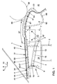
- FIG. 1 is a schematic cross section through an instrument panel 6 in one Passenger area of a motor vehicle in conjunction with an inventive Airbag arrangement 1 above a designed as a cross member module carrier 2 of a Motor vehicle shown.
- the airbag arrangement 1 has an airbag module 3, which in turn an airbag housing 4 comprises, in which a not shown here gas generator and a here only dashed shown airbag 33 in the folded ground state are included.
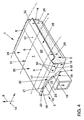
- the airbag module 3 is here in a gap region 5 between a Instrument panel 6 instrument panel base area and a dashboard associated module carrier top portion of the module carrier 2 is arranged. This is in the Region above the module carrier 2 an airbag module receiving housing 7 is provided in that, as can be seen in particular from FIGS. 4 and 5, the airbag module 3rd by means of a guide device 8 in vehicle vertical axis direction 9 seen in essentially from below the module carrier 2 and in the vehicle longitudinal direction 10th Seen essentially from behind the module carrier 2 ago led off and / or can be inserted, as shown schematically in Fig. 5 with the two arrows 11 and 12 is. This will be explained in more detail below.
- the airbag module 3 is in the fully inserted state shown.
- the airbag housing 4 box-shaped is constructed with opposing airbag housing side walls 13.
- the airbag housing 4 is in the retracted state of the airbag module 3 of receiving housing side walls 14, which are associated with the airbag housing side walls 13, encompassed, wherein in each of the Receiving housing side walls 14, a guide slot 15 is formed as the other Part of the guide device 8, a guide pin 16 on the airbag housing. 4 assigned.
- the guide slot 15 is on the receiving housing side wall 13 with a first Slot portion 17 in relation to the instrument panel 6 in Vehicle longitudinal axis 10 seen rear side wall portion 18, the rear projects beyond the module carrier 2, of a relative to the vehicle vertical axis direction 9 lower side wall portion 19 starting obliquely above to one in relation to the Vehicle vertical axis direction 9 upper side wall portion 20 out.
- the guide slot 15 is a second adjacent to the first slot portion 17 second Slit portion 21 on the receiving housing side wall 13 in the vehicle longitudinal direction 10 seen forward to about a front side wall portion 22 out. there extends the second slot portion 21, as shown only schematically in FIG. 4, First, it is essentially horizontal and then with one in comparison to the other first slot area lower slope angle led forward. This horizontal Slot region 23 runs substantially above the module carrier 2.
- Fig. 5 is a shown alternative slot design, wherein the slot is preferably approximately straight from bottom rear up. Another, alternative slot design is shown in FIG. 1 shown.
- the instrument panel 6 is in the illustration of FIG. 4 for reasons of clarity drawn only schematically and dashed. Furthermore, the airbag housing 4 with Points provided for ease of distinction of the airbag module housing 7, in which the airbag housing 4 in the inserted state approximately is received positively, wherein a receiving housing top wall 24 the Airbag housing 4 preferably covers from above in an investment connection and covered.
- the guide pins 16 are on the opposite side airbag housing walls 13th each in a front, a windshield 34 associated with the airbag housing side wall area arranged.
- the front Guide slot end 25 may be formed as a locking receptacle 26, in which the guide pin 16 in the retracted end position of the airbag module 3 is releasably latched.
- the airbag housing 4 in the assembled state preferably a gap distance to the module carrier 2, the e.g. is about 8 to 10 mm.
- the airbag housing 4 is in one Flange portion 28 with the airbag module receiving housing 7 by means of at least one Screw 29 connected.
- This flange portion 28 is in the assembled state of Airbag assembly 1, as can be seen in particular from FIG. 5, in a bottom view her easily accessible mounting portion 27 is arranged, based on the Vehicle longitudinal axis direction 10 in the direction of the vehicle interior seen behind the Module carrier 2 is located.
- the module carrier 2 runs here as a vehicle cross member between not shown here, opposite A-pillars in a range approximately at the height of a heating and Air conditioner 32, which is shown in the illustration of FIG. 5 only extremely schematically is.
- FIG. 5 only schematically and by way of example for an application is shown hindered the heating and air conditioning unit 32 as well as the immediate arrangement the airbag module 3 in the region above the module carrier 2 in the gap region 5, especially in customer service case, the easy disassembly and assembly of the airbag module.
- the airbag assembly 1 according to the invention can on the guide device 8 at previous loosening of easily accessible in the mounting area 27 screw 29 between the airbag housing 4 and the airbag module receiving housing 7 the Airbag module simply disassembled and reassembled according to the arrows 11, 12 without the dashboard 6 for access to the airbag housing would be to expand.
- the slot geometry of the guide slot 15 shown in FIG. 4 is exemplary here chosen that after the threading of the guide pin 16 in the associated Guide slots 15 along the first slot portion 17 very quickly relatively steep be guided obliquely upwards towards the front side wall portion 22 out.
- the airbag module 3 and thus in particular, the airbag 33 in the non-activated, folded ground state, as he 1, behind one of the windshield 34 associated, front Instrument panel wall area as instrument panel side airbag exit wall region 31 arranged.
- An airbag exit wall portion 31 in this instrument panel side can be formed and in FIG. 2, which shows the activated state of a structure according to FIG. 1, shown airbag outlet opening 36 has a predetermined safety distance 37 to a potential head impact area 38 of a head 39 of a vehicle occupant in one away from the windshield 34 in the direction of the vehicle interior 40 to the instrument panel-side airbag exit region 31 as a front instrument panel area adjacent head impact panel area 41.
- the safety distance 37 is set here so that the airbag 33 in FIGS. 2 and 3 schematically illustrated, activated state after a feed path in the direction Vehicle interior 40, the safety distance 37 between the airbag outlet opening 36 and the potential head impact area 38 corresponds to a gas pressure as the filling pressure which is opposite to the initial gas pressure in the airbag 33 at the beginning of Airbag activation according to predetermined limits is reduced.
- the safety distance 37 is seen here in cross section For example, roughly the straight-line, shortest connection between the beginning of the potential head impact area 38 and the beginning of the airbag exit opening 36.
- FIGS. 1 to 3 At least the Windscreen 34 facing front instrument panel area as instrument panel-side airbag outlet region 31 of a supporting body 42 be formed, in which at least one discharge nozzle, not shown here is integrated.
- the main body 42 is covered from above by means of a cover 43, the is perforated throughout, with a perforation pattern such that over the Perforations 44 as air passage openings at least in the region of at least one Outlet nozzle a diffuse ventilation is adjustable.
- a recess 45 is provided in the main body 42.
- the perforated cover 43 in this area to form a in FIG.
- the airbag 33 then pushes with its high initial Filling pressure, of z. B. 30 bar, on a receiving housing-side airbag outlet area 30th formable cover flap 47, which in turn on the instrument panel side Airbag exit region 31 formable cover flap 46 presses, so that these cover flaps 46, 47 in the schematic manner shown in FIGS. 2 and 3 in the form of a fish-mouth unfold and the airbag outlet opening 36 for inflating the airbag 33 in Release vehicle interior 40.
- retaining means in the region of the airbag outlet opening provided, e.g. a tether 48, the Aufschwenkwinkel the cover flaps 46, 47th limit.
- a certain angle of the cover flaps 46, 47 as this is shown schematically in Fig. 3, a particular Inflation direction of the airbag 33 in the direction of the vehicle interior 40 can be specified.
- the cover flap 46 is part of the airbag module receiving housing 7, which also as Shot channel can be called.
- the airbag module receiving housing 7 formed in two parts, from an abutment area 49 as a separate component, which is at the beginning of assembly by e.g. Riveting with the Dashboard bottom is connected.
- the Remainder of the airbag module receiving housing, in which the cover flap 47 can be formed with connected to abutment area 49, e.g. by means of conventional screw 50.
- the abutment region 49 is U-shaped formed with a U-base portion 51, which is connected to the instrument panel bottom becomes.
- the abutment portion 49 engages with U-legs 52 a portion of the rest the airbag module receiving housing 7, here preferably in the area above a there received gas generator, and is there by means of the screw 50th established.
- the airbag module housing housing can also on Module carrier 2 are set, as only very schematically and by way of example in the illustration of FIG. 5 is shown.
- the potential Head impact area 38 of the instrument panel 6 in part from a under energy absorption be made deformable material, such. from one with a slush skin 53 coated energy absorbing foam backing 54.
- a deformation space 55 into which the potential head impact area 38 of FIG Instrument panel 6, as shown in Fig. 3 only schematically and dashed is, under energy absorption can deform unhindered.
- FIGs. 7 to 8 that for a compact Flat construction of the airbag module 3 of the gas generator 56 laterally adjacent to the airbag 33rd is arranged, for an advantageous opening pressure of the gas jet 61 directly on the Airbag exit area is directed and the gas jet coming from the gas generator from below blows centrally in the folded airbag 33 ago.
- an airbag housing exit region 62 by means of a Protective cover 63 is closed, the airbag 33 in the folded state in Airbag housing 4 holds and the activated airbag in a central region under education at least two flap parts a housing outlet opening 64 releases, as shown in Fig. 8 it can be seen, wherein the unfolded flap parts at least partially a Form edge protection, such that they cover adjacent edge portions 65.
- the cover flaps 46 and 47 which in the instrument panel side and in the receiving housing side airbag outlet area 30, 31 can be formed, according to a further preferred embodiment, preferably as Material composite manufactured, so that they only a single, hinged flap form. This may have advantages in terms of Aufschwenkkinematik under certain circumstances.
- This Air duct 66 may, as shown in Fig. 1 only dashed lines integral with a Instrument panel underside be formed such that a bottom wall portion 67 of the instrument panel 6 forms part of the air duct wall.
- Such an air duct is regularly made of a less rigid plastic material and thus affects the deformation properties of the potential Head impact area 38 of the instrument panel not essential.
Landscapes
- Engineering & Computer Science (AREA)
- Mechanical Engineering (AREA)
- Physics & Mathematics (AREA)
- Thermal Sciences (AREA)
- Air Bags (AREA)
Abstract
Claims (10)
- Système d'airbag dans un véhicule, notamment un véhicule automobile,
avec au moins un airbag (33) qui, dans l'état de base replié, non activé, est disposé derrière une région (31) de paroi de sortie d'airbag côté tableau de bord d'un tableau de bord (6) et qui, dans l'état activé, peut être, en traversant une ouverture (36) de sortie d'airbag pouvant être formée dans la région (31) de paroi de sortie d'airbag côté tableau de bord, gonflé devant le tableau de bord (6) dans l'habitacle (40) du véhicule, sachant que l'airbag (33) au moins unique est disposé, dans l'état de base replié, non activé, derrière une région avant de paroi de tableau de bord associée à un pare-brise (34) en tant que région (31) de paroi de sortie d'airbag côté tableau de bord,
sachant que l'ouverture (36) de sortie d'airbag pouvant être formée dans la région (31) avant de paroi de tableau de bord présente une distance de sécurité prédéfinie (37) par rapport à une région (38) potentielle d'impact pour la tête d'un occupant du véhicule, région (38) qui est située dans une région (41) d'impact pour la tête de la paroi du tableau de bord qui se raccorde à la région (31) avant de paroi de tableau de bord en éloignement du pare-brise (34) et en direction de l'habitacle (40) du véhicule,
caractérisé en ce que la distance de sécurité (37) est prédéfinie de telle sorte que l'airbag (33), après avoir avancé en direction de l'habitacle (40) du véhicule d'une distance correspondant à la distance de sécurité (37) entre l'ouverture (36) de sortie d'airbag et la région (38) potentielle d'impact pour la tête, présente une pression de remplissage qui est réduite selon des valeurs limites prédéfinies par rapport à la pression de remplissage initiale dans l'airbag (33) au début de l'activation de l'airbag. - Système d'airbag selon la revendication 1, caractérisé en ce que la distance de sécurité (37) est définie de telle sorte que, après une distance d'avancement de l'airbag (33) correspondant à la distance de sécurité (37), la pression de remplissage dans l'airbag (33) dans la région (38) potentielle d'impact pour la tête est égale à au plus environ 15 %, de préférence à au plus environ 10 %, et d'une manière particulièrement préférée à au plus environ 5 %, de la pression de gaz initiale.
- Système d'airbag selon la revendication 1 ou 2, caractérisé en ce que la distance de sécurité (37) est égale, en fonction de la situation d'impact respective, à au moins environ 10 cm, de préférence à au moins environ 15 cm, et d'une manière particulièrement préférée à au moins environ 20 cm.
- Système d'airbag selon l'une quelconque des revendications 1 à 3, caractérisé en ce que l'airbag (33) présente une pression de remplissage initiale comprise entre environ 30 bars et 35 bars, et la pression de remplissage est égale à environ 2,5 à 3,5 bars après une distance d'avancement d'environ 100 mm, et de préférence à environ 1,5 à 2,5 bars après une distance d'avancement d'environ 200 mm.
- Système d'airbag selon l'une quelconque des revendications 1 à 4, caractérisé en ce que la distance de sécurité (37) est, considérée en coupe transversale à travers le tableau de bord (6), approximativement la liaison en ligne droite la plus courte entre le début - tourné vers l'ouverture (36) de sortie d'airbag - de la région (38) potentielle d'impact pour la tête et le début - tourné vers la région (38) potentielle d'impact pour la tête - de l'ouverture (36) de sortie d'airbag.
- Système d'airbag selon l'une quelconque des revendications 1 à 5, caractérisé en ce que la région (38) potentielle d'impact pour la tête est fabriquée en un matériau pouvant se déformer avec absorption d'énergie, et
en ce que, dans la région située en dessous de la région (38) potentielle d'impact pour la tête du tableau de bord (6), une chambre de déformation (55) est configurée de telle sorte que, lors d'un impact de la tête sur la région (38) potentielle d'impact pour la tête, cette région du tableau de bord (6) peut se déformer, avec absorption d'énergie, sans entrave à l'intérieur de la chambre de déformation (55). - Système d'airbag selon l'une quelconque des revendications 1 à 6, caractérisé en ce qu'un espace libre de montage (55), dans lequel peut être disposé un conduit d'air (66), est configuré en dessous de la région (38) potentielle d'impact pour la tête du tableau de bord (6) et donc, considéré dans la direction (10) de l'axe longitudinal du véhicule, en direction de l'habitacle (40) du véhicule.
- Système d'airbag selon l'une quelconque des revendications 1 à 7, caractérisé en ce qu'un boítier d'airbag (4) est configuré de telle sorte que l'airbag (33) au moins unique qui y est reçu est disposé, dans l'état de base monté, à côté d'au moins un générateur de gaz (56), et/ou
en ce que, dans la région de liaison entre une région (57) de boítier pour générateur de gaz recevant le générateur de gaz (56) et une région (58) de boítier pour airbag recevant l'airbag (33), il est prévu au moins un affaiblissement de matériau et/ou un point de (59) de rupture privilégiée qui, lors de l'action d'une force sur une des deux parties de boítier (57), notamment lors de l'action d'une force sur la région (57) de boítier pour générateur de gaz - région qui dépasse au moins partiellement dans une région (38) potentielle d'impact pour la tête, conçue déformable, du tableau de bord (6) -, se rompt et empêche la région de déformation de devenir une barrière solide. - Système d'airbag selon l'une quelconque des revendications 1 à 8, caractérisé en ce que la région d'un boítier (7) récepteur de module d'airbag qui forme une région (30) de sortie d'airbag du boítier récepteur (7) et la région du tableau de bord (6) qui forme la région (31) de paroi de sortie d'air bag dans le tableau de bord (6) s'appliquent l'une contre l'autre en liaison par application, de préférence sont conçues matériellement jointives, et forment un volet de recouvrement (46, 47) qui, afin de dégager l'ouverture de sortie d'airbag, peut être ouvert par pivotement en direction du pare-brise (34).
- Système d'airbag selon la revendication 9, caractérisé en ce que le volet de recouvrement (46) dans l'état ouvert par rabattement, au moins au début du processus de gonflage, protège le pare-brise (34) d'un impact direct de l'airbag (33) et dirige l'airbag (33) en direction de l'habitacle (40) du véhicule.
Applications Claiming Priority (5)
| Application Number | Priority Date | Filing Date | Title |
|---|---|---|---|
| DE10150660 | 2001-10-17 | ||
| DE10150660 | 2001-10-17 | ||
| DE10163686 | 2001-12-21 | ||
| DE2001163686 DE10163686A1 (de) | 2001-12-21 | 2001-12-21 | Airbaganordnung in einem Fahrzeug, insbesondere einem Kraftfahrzeug |
| PCT/EP2002/009540 WO2003033314A1 (fr) | 2001-10-17 | 2002-08-27 | Systeme d'airbag situe dans un vehicule, notamment une automobile |
Publications (2)
| Publication Number | Publication Date |
|---|---|
| EP1438218A1 EP1438218A1 (fr) | 2004-07-21 |
| EP1438218B1 true EP1438218B1 (fr) | 2005-06-15 |
Family
ID=26010373
Family Applications (1)
| Application Number | Title | Priority Date | Filing Date |
|---|---|---|---|
| EP02762465A Expired - Lifetime EP1438218B1 (fr) | 2001-10-17 | 2002-08-27 | Systeme d'airbag situe dans un vehicule, notamment une automobile |
Country Status (6)
| Country | Link |
|---|---|
| US (1) | US7722077B2 (fr) |
| EP (1) | EP1438218B1 (fr) |
| JP (1) | JP4095027B2 (fr) |
| CN (1) | CN100352700C (fr) |
| DE (1) | DE50203430D1 (fr) |
| WO (1) | WO2003033314A1 (fr) |
Cited By (1)
| Publication number | Priority date | Publication date | Assignee | Title |
|---|---|---|---|---|
| FR3121893A1 (fr) | 2021-04-14 | 2022-10-21 | Psa Automobiles Sa | Dispositif de protection à sac gonflable orienté, pour une planche de bord de véhicule |
Families Citing this family (14)
| Publication number | Priority date | Publication date | Assignee | Title |
|---|---|---|---|---|
| DE10252285A1 (de) * | 2002-11-06 | 2004-05-27 | Takata-Petri Ag | Scharnier zur Anbindung einer Klappe, insbesondere einer Motorhaube, an einem Fahrzeugkörper |
| US6991253B2 (en) * | 2003-04-11 | 2006-01-31 | Delphi Technologies, Inc. | Air bag assembly having controlled cushion deployment |
| US7874578B2 (en) * | 2009-03-12 | 2011-01-25 | Gm Global Technology Operations, Inc. | Extendable stabilizer for airbag |
| FR2959978B1 (fr) * | 2010-05-17 | 2012-08-10 | Faurecia Interieur Ind | Agencement de coussin de securite dans une planche de bord comportant un volet equipe d'un lien de retenue ayant un point d'ancrage renforce |
| DE102010051421A1 (de) * | 2010-11-17 | 2012-05-24 | Trw Automotive Gmbh | Fahrzeuginsassen-Rückhaltesystem und Verfahren zum Rückhalten eines Fahrzeuginsassen |
| EP2776290B1 (fr) * | 2011-11-11 | 2017-08-16 | Jaguar Land Rover Limited | Dispositif de protection contre les impacts avec un couvercle |
| KR102105731B1 (ko) * | 2012-07-18 | 2020-05-29 | 키 세이프티 시스템즈 인코포레이티드 | 외부 디플렉터를 갖는 에어백 모듈 |
| DE102013213791A1 (de) * | 2013-07-15 | 2015-01-15 | Volkswagen Aktiengesellschaft | Instrumententafel für ein Fahrzeug |
| US10457241B2 (en) * | 2016-10-28 | 2019-10-29 | Ford Global Technologies, Llc | Airbag assembly including a deflector |
| EP3674191B1 (fr) * | 2017-08-23 | 2021-07-14 | Honda Motor Co., Ltd. | Dispositif de coussin de sécurité gonflable pour véhicules de type à selle |
| US11364965B2 (en) * | 2017-09-29 | 2022-06-21 | Honda Motor Co., Ltd. | Saddle riding vehicle airbag device |
| DE102017223436B4 (de) * | 2017-12-20 | 2023-01-12 | Volkswagen Aktiengesellschaft | Fahrzeug mit einem in der Instrumententafel integrierten Head-Up-Display |
| DE102023112694A1 (de) | 2023-05-15 | 2024-11-21 | Dr. Ing. H.C. F. Porsche Aktiengesellschaft | Anordnung, umfassend eine Instrumententafel, ein Schusskanalgehäuse und ein Trägerelement |
| US12377808B1 (en) * | 2024-10-16 | 2025-08-05 | Faurecia Interior Systems, Inc. | Vehicle interior panel having an expandable airbag chute |
Family Cites Families (16)
| Publication number | Priority date | Publication date | Assignee | Title |
|---|---|---|---|---|
| US3817552A (en) * | 1972-08-25 | 1974-06-18 | Gen Motors Corp | Occupant restraint system |
| JPS5261822U (fr) * | 1975-10-31 | 1977-05-07 | ||
| JPS5737024A (en) * | 1980-08-12 | 1982-03-01 | Nissan Motor Co Ltd | Construction of instrument panel for automobile |
| US5087067A (en) * | 1989-05-19 | 1992-02-11 | Honda Giken Kogyo Kabushiki Kaisha | Inflatable bag assembly for protecting a vehicle occupant |
| JP2528375B2 (ja) * | 1990-06-18 | 1996-08-28 | 本田技研工業株式会社 | 乗員保護用エアバッグ装置 |
| US5320381A (en) * | 1993-07-02 | 1994-06-14 | General Motors Corporation | Air bag deployment door hinge |
| JPH07277128A (ja) * | 1994-04-04 | 1995-10-24 | Nippondenso Co Ltd | エアバッグ装置 |
| DE19611384C2 (de) | 1996-03-22 | 2001-05-31 | Hs Tech & Design | Airbagvorrichtung in einem Kraftfahrzeug |
| DE19704684C2 (de) * | 1997-02-07 | 2000-08-10 | Johnson Contr Interiors Gmbh | Beifahrerairbagvorrichtung |
| JP3784130B2 (ja) * | 1997-03-31 | 2006-06-07 | カルソニックカンセイ株式会社 | 車両用エアバッグ装置 |
| JP3405182B2 (ja) * | 1998-03-27 | 2003-05-12 | 豊田合成株式会社 | 助手席用エアバッグ装置 |
| JP3542288B2 (ja) * | 1998-10-07 | 2004-07-14 | 森六株式会社 | 自動車におけるインストルメントパネル支持構造 |
| US6619691B1 (en) * | 1998-10-23 | 2003-09-16 | Takata Corporation | Passenger-side airbag device |
| DE19860804A1 (de) * | 1998-12-30 | 2000-07-06 | Volkswagen Ag | Anordnung eines Fahrerairbags in einem Kraftfahrzeug |
| DE19913039A1 (de) | 1999-03-23 | 2000-09-28 | Bayerische Motoren Werke Ag | Befestigungsanordnung für ein Airbagmodul |
| DE19915974B4 (de) | 1999-04-09 | 2006-04-06 | Audi Ag | Insassenschutzvorrichtung mit einem Airbag für ein Kraftfahrzeug |
-
2002
- 2002-08-27 EP EP02762465A patent/EP1438218B1/fr not_active Expired - Lifetime
- 2002-08-27 CN CNB028206800A patent/CN100352700C/zh not_active Expired - Fee Related
- 2002-08-27 WO PCT/EP2002/009540 patent/WO2003033314A1/fr not_active Ceased
- 2002-08-27 DE DE50203430T patent/DE50203430D1/de not_active Expired - Lifetime
- 2002-08-27 JP JP2003536071A patent/JP4095027B2/ja not_active Expired - Fee Related
-
2004
- 2004-04-19 US US10/827,626 patent/US7722077B2/en not_active Expired - Fee Related
Cited By (1)
| Publication number | Priority date | Publication date | Assignee | Title |
|---|---|---|---|---|
| FR3121893A1 (fr) | 2021-04-14 | 2022-10-21 | Psa Automobiles Sa | Dispositif de protection à sac gonflable orienté, pour une planche de bord de véhicule |
Also Published As
| Publication number | Publication date |
|---|---|
| DE50203430D1 (de) | 2005-07-21 |
| EP1438218A1 (fr) | 2004-07-21 |
| CN1571741A (zh) | 2005-01-26 |
| WO2003033314A1 (fr) | 2003-04-24 |
| US7722077B2 (en) | 2010-05-25 |
| JP4095027B2 (ja) | 2008-06-04 |
| CN100352700C (zh) | 2007-12-05 |
| US20040195810A1 (en) | 2004-10-07 |
| JP2005505464A (ja) | 2005-02-24 |
Similar Documents
| Publication | Publication Date | Title |
|---|---|---|
| EP1438218B1 (fr) | Systeme d'airbag situe dans un vehicule, notamment une automobile | |
| DE69710381T2 (de) | Seitenaufprall-Airbag-Vorrichtung | |
| EP1048531B1 (fr) | Dispositif de protection contre le choc latéral pour les occupants d'un véhicule | |
| DE10131120A1 (de) | Baugruppe bestehend aus Fahrzeugkarosserie, Frontscheibe, Instrumententafel und Gassackmodul | |
| DE10201836A1 (de) | Airbagvorrichtung für ein Fahrzeug, insbesondere für ein Kraftfahrzeug | |
| DE10007343B4 (de) | Sicherheitseinrichtung für die Insassen eines Fahrzeugs, insbesondere für ein Kraftfahrzeug | |
| DE19738842A1 (de) | Insassenschutzvorrichtung für ein Kraftfahrzeug | |
| DE202006001826U1 (de) | Sicherheitsvorrichtung für die Fahrerseite eines Kraftfahrzeuges | |
| EP1439986B1 (fr) | Dispositif de ventilation pour un vehicule, en particulier un vehicule automobile | |
| EP1399336B1 (fr) | Boitier destine a un module de coussin gonflable | |
| DE19816080A1 (de) | Sicherheitsvorrichtung für ein Kraftfahrzeug mit einem Airbag, insbesondere einem Beifahrerairbag | |
| DE19745872A1 (de) | Airbageinrichtung | |
| DE10039800B4 (de) | Fahrzeugdach, insbesondere für ein Kraftfahrzeug | |
| DE10061946A1 (de) | Gassackmodul mit Gasführungseinrichtung | |
| DE10253403A1 (de) | Baugruppe bestehend aus Fahrzeugkarosserieteil und einem Gassackmodul | |
| DE102004014742B4 (de) | Fahrzeug mit Vorhang-Airbag | |
| DE102006005540A1 (de) | Aufblasbarer Seitenvorhang, der den Kopf des Insassen von der Fahrzeugseitenstruktur weg bewegt | |
| DE10039803B4 (de) | Fahrzeugdach, insbesondere für ein Kraftfahrzeug | |
| DE102004028513A1 (de) | Sicherheitseinrichtung für ein Fahrzeug, insbesondere für ein Kraftfahrzeug | |
| DE10163686A1 (de) | Airbaganordnung in einem Fahrzeug, insbesondere einem Kraftfahrzeug | |
| DE10039802B4 (de) | Sicherheitseinrichtung für die Insassen eines Fahrzeugs, insbesondere eines Kraftfahrzeugs | |
| DE102005050935B4 (de) | Seitenaufprallschutzeinrichtung | |
| DE10244506B4 (de) | Sicherheitseinrichtung für ein Fahrzeug, insbesondere für ein Kraftfahrzeug | |
| DE10111597A1 (de) | Insassenschutzvorrichtung für ein Fahrzeug, insbesondere für ein Kraftfahrzeug | |
| DE10163685A1 (de) | Belüftungsvorrichtung für ein Fahrzeug, insbesondere für ein Kraftfahrzeug |
Legal Events
| Date | Code | Title | Description |
|---|---|---|---|
| PUAI | Public reference made under article 153(3) epc to a published international application that has entered the european phase |
Free format text: ORIGINAL CODE: 0009012 |
|
| 17P | Request for examination filed |
Effective date: 20040517 |
|
| AK | Designated contracting states |
Kind code of ref document: A1 Designated state(s): AT BE BG CH CY CZ DE DK EE ES FI FR GB GR IE IT LI LU MC NL PT SE SK TR |
|
| GRAP | Despatch of communication of intention to grant a patent |
Free format text: ORIGINAL CODE: EPIDOSNIGR1 |
|
| RBV | Designated contracting states (corrected) |
Designated state(s): DE ES FR GB IT |
|
| GRAS | Grant fee paid |
Free format text: ORIGINAL CODE: EPIDOSNIGR3 |
|
| GRAA | (expected) grant |
Free format text: ORIGINAL CODE: 0009210 |
|
| AK | Designated contracting states |
Kind code of ref document: B1 Designated state(s): DE ES FR GB IT |
|
| PG25 | Lapsed in a contracting state [announced via postgrant information from national office to epo] |
Ref country code: IT Free format text: LAPSE BECAUSE OF FAILURE TO SUBMIT A TRANSLATION OF THE DESCRIPTION OR TO PAY THE FEE WITHIN THE PRESCRIBED TIME-LIMIT;WARNING: LAPSES OF ITALIAN PATENTS WITH EFFECTIVE DATE BEFORE 2007 MAY HAVE OCCURRED AT ANY TIME BEFORE 2007. THE CORRECT EFFECTIVE DATE MAY BE DIFFERENT FROM THE ONE RECORDED. Effective date: 20050615 |
|
| REG | Reference to a national code |
Ref country code: GB Ref legal event code: FG4D Free format text: NOT ENGLISH |
|
| REF | Corresponds to: |
Ref document number: 50203430 Country of ref document: DE Date of ref document: 20050721 Kind code of ref document: P |
|
| PG25 | Lapsed in a contracting state [announced via postgrant information from national office to epo] |
Ref country code: ES Free format text: LAPSE BECAUSE OF FAILURE TO SUBMIT A TRANSLATION OF THE DESCRIPTION OR TO PAY THE FEE WITHIN THE PRESCRIBED TIME-LIMIT Effective date: 20050926 |
|
| GBT | Gb: translation of ep patent filed (gb section 77(6)(a)/1977) |
Effective date: 20050920 |
|
| ET | Fr: translation filed | ||
| PLBE | No opposition filed within time limit |
Free format text: ORIGINAL CODE: 0009261 |
|
| STAA | Information on the status of an ep patent application or granted ep patent |
Free format text: STATUS: NO OPPOSITION FILED WITHIN TIME LIMIT |
|
| 26N | No opposition filed |
Effective date: 20060316 |
|
| PGFP | Annual fee paid to national office [announced via postgrant information from national office to epo] |
Ref country code: GB Payment date: 20140829 Year of fee payment: 13 Ref country code: FR Payment date: 20140827 Year of fee payment: 13 |
|
| GBPC | Gb: european patent ceased through non-payment of renewal fee |
Effective date: 20150827 |
|
| REG | Reference to a national code |
Ref country code: FR Ref legal event code: ST Effective date: 20160429 |
|
| PG25 | Lapsed in a contracting state [announced via postgrant information from national office to epo] |
Ref country code: GB Free format text: LAPSE BECAUSE OF NON-PAYMENT OF DUE FEES Effective date: 20150827 |
|
| PG25 | Lapsed in a contracting state [announced via postgrant information from national office to epo] |
Ref country code: FR Free format text: LAPSE BECAUSE OF NON-PAYMENT OF DUE FEES Effective date: 20150831 |
|
| PGFP | Annual fee paid to national office [announced via postgrant information from national office to epo] |
Ref country code: DE Payment date: 20180831 Year of fee payment: 17 |
|
| REG | Reference to a national code |
Ref country code: DE Ref legal event code: R119 Ref document number: 50203430 Country of ref document: DE |
|
| PG25 | Lapsed in a contracting state [announced via postgrant information from national office to epo] |
Ref country code: DE Free format text: LAPSE BECAUSE OF NON-PAYMENT OF DUE FEES Effective date: 20200303 |