EP1438472B1 - Systeme de verrouillage pour porte va-et-vient - Google Patents
Systeme de verrouillage pour porte va-et-vient Download PDFInfo
- Publication number
- EP1438472B1 EP1438472B1 EP02775643A EP02775643A EP1438472B1 EP 1438472 B1 EP1438472 B1 EP 1438472B1 EP 02775643 A EP02775643 A EP 02775643A EP 02775643 A EP02775643 A EP 02775643A EP 1438472 B1 EP1438472 B1 EP 1438472B1
- Authority
- EP
- European Patent Office
- Prior art keywords
- lock
- bolt
- door
- handle
- wall
- Prior art date
- Legal status (The legal status is an assumption and is not a legal conclusion. Google has not performed a legal analysis and makes no representation as to the accuracy of the status listed.)
- Expired - Lifetime
Links
- 208000027418 Wounds and injury Diseases 0.000 description 2
- 230000006378 damage Effects 0.000 description 2
- 208000014674 injury Diseases 0.000 description 2
- 229920002994 synthetic fiber Polymers 0.000 description 2
- 239000000872 buffer Substances 0.000 description 1
- 210000005069 ears Anatomy 0.000 description 1
- 239000000463 material Substances 0.000 description 1
- 238000012986 modification Methods 0.000 description 1
- 230000004048 modification Effects 0.000 description 1
- 238000005192 partition Methods 0.000 description 1
- 230000000630 rising effect Effects 0.000 description 1
- 239000003351 stiffener Substances 0.000 description 1
Images


Classifications
-
- B—PERFORMING OPERATIONS; TRANSPORTING
- B63—SHIPS OR OTHER WATERBORNE VESSELS; RELATED EQUIPMENT
- B63B—SHIPS OR OTHER WATERBORNE VESSELS; EQUIPMENT FOR SHIPPING
- B63B19/00—Arrangements or adaptations of ports, doors, windows, port-holes, or other openings or covers
-
- E—FIXED CONSTRUCTIONS
- E05—LOCKS; KEYS; WINDOW OR DOOR FITTINGS; SAFES
- E05C—BOLTS OR FASTENING DEVICES FOR WINGS, SPECIALLY FOR DOORS OR WINDOWS
- E05C1/00—Fastening devices with bolts moving rectilinearly
- E05C1/08—Fastening devices with bolts moving rectilinearly with latching action
- E05C1/10—Fastening devices with bolts moving rectilinearly with latching action with operating handle or equivalent member rigid with the latch
-
- E—FIXED CONSTRUCTIONS
- E05—LOCKS; KEYS; WINDOW OR DOOR FITTINGS; SAFES
- E05C—BOLTS OR FASTENING DEVICES FOR WINGS, SPECIALLY FOR DOORS OR WINDOWS
- E05C17/00—Devices for holding wings open; Devices for limiting opening of wings or for holding wings open by a movable member extending between frame and wing; Braking devices, stops or buffers, combined therewith
- E05C17/02—Devices for holding wings open; Devices for limiting opening of wings or for holding wings open by a movable member extending between frame and wing; Braking devices, stops or buffers, combined therewith by mechanical means
- E05C17/46—Devices for holding wings open; Devices for limiting opening of wings or for holding wings open by a movable member extending between frame and wing; Braking devices, stops or buffers, combined therewith by mechanical means in which the wing or a member fixed thereon is engaged by a movable fastening member in a fixed position; in which a movable fastening member mounted on the wing engages a stationary member
- E05C17/48—Devices for holding wings open; Devices for limiting opening of wings or for holding wings open by a movable member extending between frame and wing; Braking devices, stops or buffers, combined therewith by mechanical means in which the wing or a member fixed thereon is engaged by a movable fastening member in a fixed position; in which a movable fastening member mounted on the wing engages a stationary member comprising a sliding securing member
-
- E—FIXED CONSTRUCTIONS
- E05—LOCKS; KEYS; WINDOW OR DOOR FITTINGS; SAFES
- E05B—LOCKS; ACCESSORIES THEREFOR; HANDCUFFS
- E05B63/00—Locks or fastenings with special structural characteristics
- E05B63/14—Arrangement of several locks or locks with several bolts, e.g. arranged one behind the other
-
- Y—GENERAL TAGGING OF NEW TECHNOLOGICAL DEVELOPMENTS; GENERAL TAGGING OF CROSS-SECTIONAL TECHNOLOGIES SPANNING OVER SEVERAL SECTIONS OF THE IPC; TECHNICAL SUBJECTS COVERED BY FORMER USPC CROSS-REFERENCE ART COLLECTIONS [XRACs] AND DIGESTS
- Y10—TECHNICAL SUBJECTS COVERED BY FORMER USPC
- Y10T—TECHNICAL SUBJECTS COVERED BY FORMER US CLASSIFICATION
- Y10T292/00—Closure fasteners
- Y10T292/08—Bolts
- Y10T292/0801—Multiple
- Y10T292/0834—Sliding
- Y10T292/0836—Operating means
- Y10T292/0846—Rigid
-
- Y—GENERAL TAGGING OF NEW TECHNOLOGICAL DEVELOPMENTS; GENERAL TAGGING OF CROSS-SECTIONAL TECHNOLOGIES SPANNING OVER SEVERAL SECTIONS OF THE IPC; TECHNICAL SUBJECTS COVERED BY FORMER USPC CROSS-REFERENCE ART COLLECTIONS [XRACs] AND DIGESTS
- Y10—TECHNICAL SUBJECTS COVERED BY FORMER USPC
- Y10T—TECHNICAL SUBJECTS COVERED BY FORMER US CLASSIFICATION
- Y10T292/00—Closure fasteners
- Y10T292/08—Bolts
- Y10T292/096—Sliding
- Y10T292/0969—Spring projected
- Y10T292/097—Operating means
-
- Y—GENERAL TAGGING OF NEW TECHNOLOGICAL DEVELOPMENTS; GENERAL TAGGING OF CROSS-SECTIONAL TECHNOLOGIES SPANNING OVER SEVERAL SECTIONS OF THE IPC; TECHNICAL SUBJECTS COVERED BY FORMER USPC CROSS-REFERENCE ART COLLECTIONS [XRACs] AND DIGESTS
- Y10—TECHNICAL SUBJECTS COVERED BY FORMER USPC
- Y10T—TECHNICAL SUBJECTS COVERED BY FORMER US CLASSIFICATION
- Y10T292/00—Closure fasteners
- Y10T292/08—Bolts
- Y10T292/096—Sliding
- Y10T292/0969—Spring projected
- Y10T292/097—Operating means
- Y10T292/0997—Rigid
Definitions
- the present invention concerns a lock for a swinging door comprising a lock casing and a bolt spring-loaded for engagement with a stationary engagement member of a door case or the like.
- a lock has its bolt movable between a position extending outside a fore-end of the lock and an associated door leaf (locking position) and a position retracted to within the casing and the door leaf (open position).
- a lock having a bolt spring-loaded towards its open position may cause injury to people due to the protruding bolt. This is particularly the case in marine applications, where a ship or yacht is frequently exposed to movements of the sea that may cause unintentional and unexpected swinging movement of a door that is not properly locked or otherwise secured.
- One object of the present invention is to provide a lock, particularly, but not exclusively for marine applications, that does expose people to injury risk due to a swinging door.
- a further object of the present invention is to provide a lock - with or without a normal protruding spring loaded latch bolt - that is not sensitive to the angle of a door leaf in an open position as regards keeping the door in such open position.
- a further object of the present invention is to provide a lock that is readily adaptable to different thickness of door leaves.
- a still further object is to provide a lock, the handle of which is comfortably accessible and operable even when a relatively thin door leaf is concerned.
- the present invention provides a lock for a swinging door comprising a lock casing having a fore-end, a first side wall and a second side wall opposed to said first side wall, at least one bolt spring loaded for engagement with a stationary engagement member of a door case or the like, said at least one bolt being moveable between a locking position in which it does not extend beyond said fore-end, and an open position, in which it is retracted into said lock casing, wherein said lock casing has an opening in its fore-end and side first side wall, said opening enabling engagement between said stationary engagement member and said at least one bolt, said at least one bolt being integral with a first handle member in a first unitary block slidably guided relative the first side wall, and the second handle member being integral with a second unitary block slidably guided relative to the second side wall and joined to the first unitary block to form a unitary handle and bolt member, remarkable in that a dividing wall is arranged between the first and second handle members, the
- Fig. 1 illustrates a typical use of a lock 11 according to an example which is not part of the invention as claimed mounted in a door leaf 12.
- the door leaf is swingable about a hinge 13 attached to a door post 14 mounted to a wall 15 between a first, closed position, and a second, open position.
- the lock engages a first stationary engagement member 16 mounted onto a wall 17 close to a door post 18 so as to prevent the door from opening.
- the lock is shown to engage a second stationary engagement member 19 mounted onto a post 20 protruding from the wall 15 as an optional means to keep the door in the open position and to prevent uncontrolled swinging thereof.
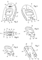
- FIG. 2 and 3 The perspective views of Figs. 2 and 3 as well as the front view of Fig. 4 reveal a lock case 21 having two opposed walls 22 and 23 and a front wall, or, fore-end 24 joining the opposed walls.
- the distance between the opposed walls defines the thickness of a door in which to mount the lock.
- An opening 25 is provided in the fore-end and the opposed walls 22, 23.
- the opening may be provided in the fore-end and one of the walls only.
- the opening is provided to give access to a bolt 26 movable within the lock case between a locking position shown and a retracted, open position.
- Openings 27, 28 are provided in the opposed walls 22, 23, respectively, for a first and a second handle member 29, 30, respectively, for the manual operation of the bolt 26 by gripping with a hand into a respective opening 29', 30' in the handle members.
- Fig. 5 shows the bolt 26 to be integral with the first handle member 29 in a first unitary block 31, preferably made of a moldable synthetic material.
- the block 31 has a generally flat surface 32 from which the first handle member rises so as to protrude through the opening 27 in the first side wall 22 as seen in Fig. 2.
- Fig. 6 shows a second unitary block 33, also preferably made of a moldable synthetic material, the second handle member 30 rising from a generally flat surface 34 thereof so as to protrude through the opening 28 in the second side wall 23 as seen in Fig. 3.
- Fig. 7 shows a guide frame 35 having a general U-shape with two parallel legs 36, 37 extending from a joining web portion 38.
- the legs have inwardly turned ends 39, 40, respectively
- the guide frame being preferably made of the same or a similar moldable material as the two blocks 31, 33, is insertable and fits between the opposed walls 22, 23 of the lock casing as indicated in Fig. 8.
- bosses 41, 42 (Fig. 7) formed at the end surfaces 39', 40' of the inwardly turned ends 39, 40, respectively, extend through corresponding apertures 43, 44 (Fig. 8), respectively, made in the fore-end 24.
- the two blocks 31, 33 are shaped to match one another so as to form together a unitary handle and bolt member by being brought together as indicated in Fig. 8 and inserted within the confines of the legs 36, 37 of the guide frame 35 as indicated by dash-dotted lines extending between the blocks 31, 33.
- the guide frame is introduced between the opposed walls 22, 23 of the lock casing as indicated by dash-dotted lines extending through the apertures 43, 44.
- the guide frame is in a position where the bolt 26 is accessible through the opening 25 in the lock casing. A seen in Figs.
- the web portion 38 of the guide frame has a protrusion 45 on its side facing the side wall 22 of the lock casing. In the final position of the guide frame, this protrusion snaps into a corresponding aperture 46 in the wall 22 and, thus, keeps the guide frame in its correct position.
- the external dimensions of the guide frame define the size of a recess in a door in which to mount the lock.
- the lock is provided with an optional -privacy latch' 47, i.e., a latch provided on the interior side of the lock to prevent intrusion.
- This latch is pivotally mounted on a trunnion 48 integrally protruding from the web portion 38 of the guide frame so as to be accessible through a correspondingly enlarged portion of the aperture 46 as seen in Fig. 2.
- the latch has a protruding pin 47'.
- a coil spring 49 is mounted on the trunnion 48 outside the latch 47 and abuts backward interior walls 50, 51 of the assembled handle members 31, 32 so as to urge them and the bolt 26 towards the fore-end 24 of the lock, i.e., the locking position of the bolt. From this locking position, the bolt is manually retractable by operation of either of the handle members 29, 30.
- the sliding motion of the two blocks 31, 33 and the bolt 26 is guided by the inner surfaces of the opposed walls 22, 23 of the lock casing as well as by the opposed surfaces of the legs 36, 37 of the guide frame 35.
- the protruding pin 47' of the privacy latch 47 is effective to either abut the assembled walls 50, 51 in its latching position, thereby preventing movement of the assembled handle members 29, 30 in their opening direction, or, pivoted to its free position, to pass through a hole 51' provided in the assembled walls 50, 51 to allow movement of the handle members in their opening direction.
- widened portions 26a, 26b thereof abutting the inner side of the fore-end 26 on either sides of the opening 25 as seen in Figs. 2 and 3.
- the widened portions are rib-like and have the full thickness of the block 31 (except for the handle protrusion) as best seen in Figs. 3 and 5, whereas the, bolt has about half the thickness of the block 31 as best seen in Fig. 4. Consequently, the rib-like portions 26a, 26b serve as stiffeners for the bolt 26.
- the second block 33 has corresponding rib-like protrusions 52, 53 as seen in Fig. 6.
- the width of the bolt 26 with its widening portions 26a, 26b is adapted to the free width between the inwardly turned ends 39, 40 of the legs 36, 37 of the guide frame 35. This is true also for the total external width of the rib-like protrusions 52, 53.
- both blocks 31" and 33" are equal and are both provided with a bolt 26" as previously described.
- one block 31" is provided with a protruding, chamfered bolt 54.
- This embodiment is particularly intended for applications where there is a need for a protruding bolt in one position of a door but this protruding bolt is not suited in another position of the door.
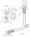
- Fig. 13 where the protruding bolt is used to lock the door in its closed position, whereas a bolt 26" is more suited to keep the door in its open position by engagement with a fixed retaining member 55.
- the bolt 54 is connected to the block 31" by means of matching ribs 56a, 56b and grooves 57a, 57b integrally formed on the bolt and in the block 33", respectively.
- the bolt 54 is formed with a channel 58 having opposed walls 59a, 59b.
- a screw 60 having a head 61 located in operation within opposed slots 62a, 62b formed in the walls 59a, 59b is threaded into a hole 63 formed in a post 64 integral with the block 31" (visible only in the lower block 33").
- the embodiment of the lock is shown to be adapted to varying door leave thickness, particularly thicker door leaves.
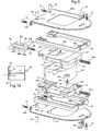
- a door leaf thickness adapter 65 As shown in Fig. 9, this adapter is a structure having a closed wall 66 shaped in conformity with the equally shaped, exterior surfaces of the walls 67 of the handle openings 29", 30".
- the sleeve-like adapter will enclose the walls 66 and - depending on the actual door leaf thickness - be more or less telescopingly slid onto the walls 67 of both handle blocks.
- a partition or dividing wall is normally mounted between the two blocks 31, 33.
- Such dividing wall may be integral with one of the blocks, or, may be a separate structure inserted between them. Anyhow, when a relatively thin door is concerned, the free space to grip a handle member to operate the door may be limited by a fixed wall to an extent that makes operation uncomfortable.
- the present invention provides a solution to that problem by making the dividing wall swingable a limited angle to either sides of a central plane between the blocks 31, 33.
- An example of such a swingable dividing wall 71 is shown in Fig. 9.
- the dividing wall 71 is shown to be integrally molded with the wall 66 of the adapter 65, as particularly appears from the section of Fig. 10.
- a relatively thin hinge portion 72 connects the wall 66 to the dividing wall 71 to make the latter easily swingable when touched by fingers inserted into the handle of the lock to operate it.
- the dividing wall is provided with swing restricting projections 73 at its base connected to the wall 66 so as to restrict swinging movement of the dividing wall in positions still preventing view through the lock by abutment against the wall 66.
- the dividing wall When inserting a hand, or, at least some fingers of a hand into a handle opening, the dividing wall will deflect and swing towards the opposite side of the lock, thereby providing essentially increased access space for operating the handle while still preventing view through the lock and the door.
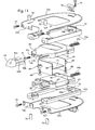
- the casing and the fore-end and the lock according to the embodiment is divided in two halves 22a, 22b and 24a, 24b as shown in Figs. 9, 11, 12 and 13.
- the guide frame is divided in two parts 35a, 35b, guiding movement of the blocks 31" and 33", respectively.
- each of the blocks 31", 33" is urged by a separate spring 49a, 49b towards the locking positions of the bolt 26" and the chamfered bolt 54.
- the springs are engaged on respective trunnions 48a, 48b formed on the guide frames 35a, 35b, respectively, and extend into holes 74a, 74b formed in the respective block 31", 33".
- Figs. 9 and 11 Shown in Figs. 9 and 11 are also screws 75 for the attachment of the lock casing halves to a door leaf, as well as rubber elastic buffers 76 to be partly introduced into corresponding holes 77 in the lock casing to prevent hard impact of the lock against encountered objects, such as portions of the wall 17 and the post 20 shown in Fig.1.
- FIGs. 9 and 11 show connectors 78 for connecting the casing parts 22a, 22b to a respective guide frame 35a, 35b by snapping into apertures 79 provided in the guide frames.
Landscapes
- Engineering & Computer Science (AREA)
- Mechanical Engineering (AREA)
- Chemical & Material Sciences (AREA)
- Combustion & Propulsion (AREA)
- Ocean & Marine Engineering (AREA)
- Casings For Electric Apparatus (AREA)
- Lock And Its Accessories (AREA)
- Control Of Vending Devices And Auxiliary Devices For Vending Devices (AREA)
- Gates (AREA)
- Patch Boards (AREA)
Claims (6)
- Serrure pour une porte battante (12) comprenant un boîtier de serrure (21) ayant une extrémité avant (24), une première paroi latérale (22) et une seconde paroi latérale (23) opposée à ladite première paroi latérale (22), au moins un pêne (26) à ressort pour s'engager dans un élément d'engagement fixe (16) d'un dormant (18) ou analogue, ledit au moins un pêne (26) étant déplaçable entre une position de verrouillage dans laquelle il ne s'étend pas au-delà de ladite extrémité avant (24), et une position ouverte, dans laquelle il est rétracté dans ledit boîtier de serrure (21), dans laquelle ledit boîtier de serrure possède une ouverture (25) dans son extrémité avant (24) et sa première paroi latérale (22), ladite ouverture permettant un engagement entre ledit élément d'engagement fixe (16) et ledit au moins un pêne (26), ledit au moins un pêne (26) étant monobloc avec un premier élément de poignée (29) dans un premier bloc unitaire (31) guidé en coulissant par rapport à la première paroi latérale (22), et un second élément de poignée (30) étant monobloc avec un second bloc unitaire (33) assemblé au premier bloc unitaire (31) pour former un élément de pêne et poignée unitaire, dans laquelle ledit élément de pêne et poignée unitaire est guidé en coulissant entre ladite première paroi latérale (22) et ladite seconde paroi latérale (23), dans laquelle une paroi de séparation (71) est disposée entre le premier et le second éléments de poignée (29, 30), la paroi de séparation étant articulée (72) au niveau d'un côté pour permettre au moins une déviation limitée de celle-ci après une manoeuvre manuelle de l'un du premier et du second éléments de poignée (29, 30).
- Serrure selon la revendication 1, caractérisée en ce que le premier bloc unitaire (31) et le second bloc unitaire (33) sont séparés mais mutuellement raccordés par un adaptateur d'épaisseur de vantail (65) transférant un mouvement entre les blocs.
- Serrure selon la revendication 2, caractérisée en ce que la paroi de séparation (71) est intégralement moulée avec la paroi (66) de l'adaptateur d'épaisseur de vantail (65).
- Serrure selon la revendication 2, caractérisée en ce que l'adaptateur d'épaisseur (65) est une structure ressemblant à un manchon, raccordée de manière télescopique aux deux desdits blocs.
- Serrure selon la revendication 3, caractérisée en ce que la paroi de séparation (71) est disposée à l'intérieur de la structure ressemblant à un manchon.
- Serrure selon la revendication 1, caractérisée en ce que le second bloc unitaire (33") possède un second pêne (26").
Applications Claiming Priority (3)
| Application Number | Priority Date | Filing Date | Title |
|---|---|---|---|
| US969822 | 2001-10-04 | ||
| US09/969,822 US6631931B2 (en) | 2001-10-04 | 2001-10-04 | Lock for a swinging door |
| PCT/SE2002/001818 WO2003029587A1 (fr) | 2001-10-04 | 2002-10-04 | Systeme de verrouillage pour porte va-et-vient |
Publications (2)
| Publication Number | Publication Date |
|---|---|
| EP1438472A1 EP1438472A1 (fr) | 2004-07-21 |
| EP1438472B1 true EP1438472B1 (fr) | 2006-05-24 |
Family
ID=25516042
Family Applications (1)
| Application Number | Title | Priority Date | Filing Date |
|---|---|---|---|
| EP02775643A Expired - Lifetime EP1438472B1 (fr) | 2001-10-04 | 2002-10-04 | Systeme de verrouillage pour porte va-et-vient |
Country Status (5)
| Country | Link |
|---|---|
| US (1) | US6631931B2 (fr) |
| EP (1) | EP1438472B1 (fr) |
| CN (1) | CN1304716C (fr) |
| GB (1) | GB2397332B (fr) |
| WO (1) | WO2003029587A1 (fr) |
Families Citing this family (31)
| Publication number | Priority date | Publication date | Assignee | Title |
|---|---|---|---|---|
| US6957513B2 (en) * | 2001-11-07 | 2005-10-25 | Newell Operating Company | Integrated tilt/sash lock assembly |
| DE10343230A1 (de) * | 2002-09-17 | 2004-09-23 | Southco, Inc. | Zweifach wirkendes Ladeflächen-Schnappschloß |
| US7607262B2 (en) | 2002-11-07 | 2009-10-27 | Newell Operating Company | Integrated tilt/sash lock assembly |
| ATE416288T1 (de) * | 2003-09-26 | 2008-12-15 | Socamel S A S | Türverschlussanordnung |
| US7222891B2 (en) * | 2004-10-23 | 2007-05-29 | Southco, Inc. | Flush mount sliding panel latch |
| WO2006132613A1 (fr) * | 2005-06-03 | 2006-12-14 | Linpac Materials Handling | Assemblage de conteneur et appareil de verrouillage et procédés apparentés |
| DE202006001052U1 (de) * | 2006-01-23 | 2006-05-11 | Fairchild Fasteners Europe - Camloc Gmbh | Verschlusselement |
| US10107021B1 (en) | 2006-03-28 | 2018-10-23 | Vision Industries Group, Inc. | Window vent stop with plastic spring member for bi-directional biasing of the tumbler |
| US11047157B1 (en) | 2006-03-28 | 2021-06-29 | Vision Industries Group, Inc. | Vent stop |
| US8235430B2 (en) | 2006-03-28 | 2012-08-07 | Vision Industries, Inc. | Window vent stop with flexible side engagement pieces |
| US8205920B2 (en) | 2008-04-28 | 2012-06-26 | Newell Operating Company | Sash lock with forced entry resistance |
| US9840860B2 (en) | 2009-05-29 | 2017-12-12 | Vision Industries Group, Inc. | Double-action, adjustable, after-market sash stop |
| CN102905480A (zh) * | 2011-07-25 | 2013-01-30 | 鸿富锦精密工业(深圳)有限公司 | 电子装置壳体 |
| US10704297B2 (en) | 2014-03-06 | 2020-07-07 | Vision Industries, Inc. | Impact resistant lock and tilt latch combination for a sliding sash window |
| US10570652B2 (en) | 2014-03-06 | 2020-02-25 | Vision Industries Group, Inc. | Integrated sash lock and tilt latch combination using one lock for two tilt latches |
| US10844642B2 (en) | 2014-03-06 | 2020-11-24 | Vision Industries Group, Inc. | Combination four-position sash lock and tilt latch also functioning as a window opening control device |
| US10119310B2 (en) | 2014-03-06 | 2018-11-06 | Vision Industries Group, Inc. | Combination sash lock and tilt latch with improved interconnection for blind mating of the latch to the lock |
| US10865592B2 (en) | 2014-03-06 | 2020-12-15 | Vision Industries Group, Inc. | Sash lock and tilt latch also functioning as a window vent stop, with automatic locking upon closure |
| US11168492B1 (en) | 2017-02-16 | 2021-11-09 | Vision Industries Group, Inc. | Tamper resistant sash lock |
| US10633897B2 (en) | 2017-02-16 | 2020-04-28 | Vision Industries Group, Inc. | Tamper-resistant lock |
| US10844636B2 (en) | 2017-05-23 | 2020-11-24 | Vision Industries Group, Inc. | Combination forced entry resistant sash lock and tilt latch, also functioning as a window opening control device |
| US11118376B1 (en) | 2017-10-18 | 2021-09-14 | Vision Industries Group, Inc. | Combination sash lock and tilt latch and slidable window vent stop |
| US10544623B2 (en) * | 2018-02-14 | 2020-01-28 | Charles Young | Security screen door for sliding doors |
| CH715020B1 (de) * | 2018-05-24 | 2022-06-15 | Hawa Sliding Solutions Ag | Schloss, Beschlag, Schliessblech und Schliessvorrichtung für Schiebetüren sowie Schiebetüranlage. |
| US11168495B1 (en) | 2018-08-01 | 2021-11-09 | Vision Industries Group, Inc. | Automatically resetting window vent stop with dual safety features |
| US11187010B1 (en) | 2019-09-19 | 2021-11-30 | Vision Industries, Inc. | Forced-entry-resistant sash lock |
| GB2600745B (en) * | 2020-11-09 | 2026-03-18 | Andersen Jesper | Child proof latch and method of fitting |
| GB202203591D0 (en) * | 2022-03-15 | 2022-04-27 | Andersen Jesper | Child safety lock |
| US12428886B1 (en) | 2022-06-16 | 2025-09-30 | Vision Industries Group, Inc. | Forced entry resistant sash lock also configured to snap into the meeting rail of the sash window |
| US12359477B1 (en) | 2022-06-16 | 2025-07-15 | Vision Industries Group, Inc. | Window sash lock configured for screwless snap-in installation onto a meeting rail |
| US12467297B1 (en) | 2023-07-18 | 2025-11-11 | Vision Industries Group, Inc. | Window balance assembly with improved brake arrangement |
Family Cites Families (19)
| Publication number | Priority date | Publication date | Assignee | Title |
|---|---|---|---|---|
| US69235A (en) | 1867-09-24 | William a | ||
| US813343A (en) * | 1905-08-19 | 1906-02-20 | Albert D Bartlett | Shutter-fastener. |
| US1058952A (en) | 1912-09-23 | 1913-04-15 | Forrest T Durner | Latch. |
| US1687388A (en) | 1926-07-30 | 1928-10-09 | Rigo Jorge | Lock |
| US2060284A (en) | 1935-08-28 | 1936-11-10 | Clement N Curtis | Fastener for closures |
| US2431105A (en) | 1945-10-19 | 1947-11-18 | Gaylord A Brinson | Lock and latch |
| GB1049948A (en) | 1963-03-07 | 1966-11-30 | Jose Alfonso Echavarria | Improvements in or relating to lock mechanisms |
| US3774420A (en) | 1971-06-03 | 1973-11-27 | Keystone Consolidated Ind Inc | Interlocking dead bolt lock and strike |
| US3782139A (en) | 1972-01-21 | 1974-01-01 | Briggs & Stratton Corp | Latch mechanism |
| US3909051A (en) * | 1974-04-05 | 1975-09-30 | Miwa Lock Company Ltd | Narrow profile door latch |
| US3937504A (en) | 1974-10-03 | 1976-02-10 | Mcelroy Richard Lee | Push and pull door latch |
| DK122080A (da) | 1980-03-21 | 1981-09-22 | B F Jensen | Snaplaas med forskydelig fjederbelastet skudrigel |
| US4440428A (en) * | 1981-09-01 | 1984-04-03 | Jessup Frank L | Apparatus for delaying the closing of a door |
| US5193707A (en) * | 1990-08-07 | 1993-03-16 | Asahi Kogaku Kogyo Kabushiki Kaisha | Lid structure including slidable lock member |
| US5174617A (en) * | 1992-02-18 | 1992-12-29 | Slideline, Inc. | Latch for "sliding" door or window |
| US5669639A (en) * | 1996-05-09 | 1997-09-23 | Lawrence; Barry G. | Window latch mechanism |
| US6021603A (en) * | 1998-04-07 | 2000-02-08 | Ashland Products, Inc. | Tilt-latch with bolt stop |
| AU3856500A (en) | 1999-02-08 | 2000-08-25 | Eric D. Hyp | Reversible slam action latch |
| CN2399494Y (zh) * | 1999-12-24 | 2000-10-04 | 张柏堉 | 管形锁的双弹簧缓冲位移门栓装置 |
-
2001
- 2001-10-04 US US09/969,822 patent/US6631931B2/en not_active Expired - Lifetime
-
2002
- 2002-10-04 WO PCT/SE2002/001818 patent/WO2003029587A1/fr not_active Ceased
- 2002-10-04 EP EP02775643A patent/EP1438472B1/fr not_active Expired - Lifetime
- 2002-10-04 CN CNB028197232A patent/CN1304716C/zh not_active Expired - Fee Related
- 2002-10-04 GB GB0409199A patent/GB2397332B/en not_active Expired - Fee Related
Also Published As
| Publication number | Publication date |
|---|---|
| CN1304716C (zh) | 2007-03-14 |
| US6631931B2 (en) | 2003-10-14 |
| WO2003029587B1 (fr) | 2004-04-08 |
| GB0409199D0 (en) | 2004-05-26 |
| CN1564901A (zh) | 2005-01-12 |
| US20030067173A1 (en) | 2003-04-10 |
| GB2397332B (en) | 2005-05-11 |
| WO2003029587A1 (fr) | 2003-04-10 |
| GB2397332A (en) | 2004-07-21 |
| EP1438472A1 (fr) | 2004-07-21 |
Similar Documents
| Publication | Publication Date | Title |
|---|---|---|
| US6631931B2 (en) | Lock for a swinging door | |
| US4683736A (en) | Cabinet lock with recessed handle | |
| US9341003B2 (en) | Latch for storage case | |
| US7797838B2 (en) | Retractable blade knife with opening assisted mechanism | |
| US4892338A (en) | Plural point door lock and flush-mountable operating mechanism with detent | |
| US6463770B1 (en) | Lock for a computer | |
| US6655540B2 (en) | Strap attaching structure and electronic apparatus | |
| US7881054B2 (en) | Computer lock system | |
| US4416126A (en) | Luggage latching system | |
| JPH06119082A (ja) | 情報処理装置 | |
| US4882919A (en) | Flush mounted panel lock construction | |
| US6536244B1 (en) | Computer security device | |
| US6257631B1 (en) | Draw latch | |
| GB2275500A (en) | Lock assembly | |
| EP3919709A1 (fr) | Verrouillage de porte à panneau | |
| AU2019271986A1 (en) | Lock assembly | |
| US11168495B1 (en) | Automatically resetting window vent stop with dual safety features | |
| KR102518541B1 (ko) | 그립 일체형 인사이드핸들 | |
| US5669256A (en) | Door lock mechanism with a release button | |
| JP7542492B2 (ja) | ケーブル連結機構 | |
| US20020080560A1 (en) | Housing for electronic device | |
| US12516558B2 (en) | Latch and locking structure | |
| KR101958223B1 (ko) | 사물함 도어 개폐장치 | |
| EP0955433A1 (fr) | Système de verrou pour cadenas | |
| KR102044630B1 (ko) | 사물함 도어용 경첩 |
Legal Events
| Date | Code | Title | Description |
|---|---|---|---|
| PUAI | Public reference made under article 153(3) epc to a published international application that has entered the european phase |
Free format text: ORIGINAL CODE: 0009012 |
|
| 17P | Request for examination filed |
Effective date: 20040409 |
|
| AK | Designated contracting states |
Kind code of ref document: A1 Designated state(s): AT BE BG CH CY CZ DE DK EE ES FI FR GB GR IE IT LI LU MC NL PT SE SK TR |
|
| AX | Request for extension of the european patent |
Extension state: AL LT LV MK RO SI |
|
| 17Q | First examination report despatched |
Effective date: 20050531 |
|
| REG | Reference to a national code |
Ref country code: DE Ref legal event code: 8566 |
|
| GRAP | Despatch of communication of intention to grant a patent |
Free format text: ORIGINAL CODE: EPIDOSNIGR1 |
|
| GRAS | Grant fee paid |
Free format text: ORIGINAL CODE: EPIDOSNIGR3 |
|
| GRAA | (expected) grant |
Free format text: ORIGINAL CODE: 0009210 |
|
| AK | Designated contracting states |
Kind code of ref document: B1 Designated state(s): FR |
|
| ET | Fr: translation filed | ||
| PLBE | No opposition filed within time limit |
Free format text: ORIGINAL CODE: 0009261 |
|
| STAA | Information on the status of an ep patent application or granted ep patent |
Free format text: STATUS: NO OPPOSITION FILED WITHIN TIME LIMIT |
|
| 26N | No opposition filed |
Effective date: 20070227 |
|
| PGFP | Annual fee paid to national office [announced via postgrant information from national office to epo] |
Ref country code: FR Payment date: 20141008 Year of fee payment: 13 |
|
| REG | Reference to a national code |
Ref country code: FR Ref legal event code: ST Effective date: 20160630 |
|
| PG25 | Lapsed in a contracting state [announced via postgrant information from national office to epo] |
Ref country code: FR Free format text: LAPSE BECAUSE OF NON-PAYMENT OF DUE FEES Effective date: 20151102 |