EP1438516B1 - Reibungskupplung mit gesteuerter nachstellvorrichtung, insbesondere für kraftfahrzeuge - Google Patents
Reibungskupplung mit gesteuerter nachstellvorrichtung, insbesondere für kraftfahrzeuge Download PDFInfo
- Publication number
- EP1438516B1 EP1438516B1 EP02801929A EP02801929A EP1438516B1 EP 1438516 B1 EP1438516 B1 EP 1438516B1 EP 02801929 A EP02801929 A EP 02801929A EP 02801929 A EP02801929 A EP 02801929A EP 1438516 B1 EP1438516 B1 EP 1438516B1
- Authority
- EP
- European Patent Office
- Prior art keywords
- plate
- fact
- clutch according
- segment
- ramps
- Prior art date
- Legal status (The legal status is an assumption and is not a legal conclusion. Google has not performed a legal analysis and makes no representation as to the accuracy of the status listed.)
- Expired - Lifetime
Links
- 238000006243 chemical reaction Methods 0.000 claims abstract description 26
- 230000000295 complement effect Effects 0.000 claims abstract description 11
- 230000001133 acceleration Effects 0.000 claims description 15
- 239000011324 bead Substances 0.000 claims description 6
- 239000002184 metal Substances 0.000 claims description 3
- 230000001788 irregular Effects 0.000 claims 1
- 238000012544 monitoring process Methods 0.000 abstract 1
- 230000014759 maintenance of location Effects 0.000 description 4
- 238000013016 damping Methods 0.000 description 3
- 241000735470 Juncus Species 0.000 description 2
- 238000002485 combustion reaction Methods 0.000 description 2
- 230000000694 effects Effects 0.000 description 2
- 230000000717 retained effect Effects 0.000 description 2
- 210000002105 tongue Anatomy 0.000 description 2
- 238000013459 approach Methods 0.000 description 1
- 230000004323 axial length Effects 0.000 description 1
- 230000000903 blocking effect Effects 0.000 description 1
- 230000008878 coupling Effects 0.000 description 1
- 238000010168 coupling process Methods 0.000 description 1
- 238000005859 coupling reaction Methods 0.000 description 1
- 238000006073 displacement reaction Methods 0.000 description 1
- 229940082150 encore Drugs 0.000 description 1
- 239000000463 material Substances 0.000 description 1
- 230000010355 oscillation Effects 0.000 description 1
- 230000003071 parasitic effect Effects 0.000 description 1
- 238000010079 rubber tapping Methods 0.000 description 1
- 238000007493 shaping process Methods 0.000 description 1
- 238000003466 welding Methods 0.000 description 1
Images



Classifications
-
- F—MECHANICAL ENGINEERING; LIGHTING; HEATING; WEAPONS; BLASTING
- F16—ENGINEERING ELEMENTS AND UNITS; GENERAL MEASURES FOR PRODUCING AND MAINTAINING EFFECTIVE FUNCTIONING OF MACHINES OR INSTALLATIONS; THERMAL INSULATION IN GENERAL
- F16D—COUPLINGS FOR TRANSMITTING ROTATION; CLUTCHES; BRAKES
- F16D13/00—Friction clutches
- F16D13/58—Details
- F16D13/75—Features relating to adjustment, e.g. slack adjusters
-
- F—MECHANICAL ENGINEERING; LIGHTING; HEATING; WEAPONS; BLASTING
- F16—ENGINEERING ELEMENTS AND UNITS; GENERAL MEASURES FOR PRODUCING AND MAINTAINING EFFECTIVE FUNCTIONING OF MACHINES OR INSTALLATIONS; THERMAL INSULATION IN GENERAL
- F16D—COUPLINGS FOR TRANSMITTING ROTATION; CLUTCHES; BRAKES
- F16D13/00—Friction clutches
- F16D13/58—Details
- F16D13/75—Features relating to adjustment, e.g. slack adjusters
- F16D13/757—Features relating to adjustment, e.g. slack adjusters the adjusting device being located on or inside the clutch cover, e.g. acting on the diaphragm or on the pressure plate
Definitions
- the present invention relates to a friction clutch, for a motor vehicle with a heat engine, and relates more particularly to a clutch equipped with a device for catching the game due mainly to the wear of the friction linings, said device operating continuously as and as wear of said linings.
- a conventional friction clutch generally comprises a reaction plate, possibly in two parts for forming a damping flywheel, set in rotation on a first shaft, usually a driving shaft such as the crankshaft of the internal combustion engine, and supporting by its outer periphery a lid to which is attached at least one pressure plate.
- the pressure plate is integral in rotation with the lid and the reaction plate while being able to move axially under the load of elastic means with axial action controlled, generally a metal diaphragm bearing on the lid, while a friction disc, bearing friction linings at its outer periphery, integral in rotation with a shaft, usually a driven shaft such as the input shaft of the gearbox, is interposed between the pressure plate and the reaction plate of to be clamped together when the clutch is in the engagement position.
- the diaphragm controls the axial displacement of the pressure plate when it is actuated by a release stop.
- Document FR 2 426 834 discloses a backlash device in which a first plate, in this case the pressure plate, is in two coaxial parts that are axially displaceable with respect to one another so that that the overall thickness of the first plate increases as wear increases.
- the two coaxial portions of the first plate are axially displaceable relative to each other by means of a catch-up device which comprises ramp means carried in complementary manner by the two coaxial parts which are furthermore displaceable. rotation relative to each other in the direction of increasing said overall thickness and prevented from rotating relative to each other in the opposite direction to the previous by unidirectional means.
- the relative rotational movement of the coaxial parts is controlled by a trigger sensitive to the state of wear and performed by a circumferential action elastic means coupled between said two coaxial parts.
- Such a device effectively makes it possible to continuously catch the play due to the wear of the friction linings.
- a friction clutch in particular for a motor vehicle, of the type comprising a reaction plate intended to be wedged in rotation on a drive shaft, a friction disc, carrying at its outer periphery friction linings, intended to be rotatably mounted on a driven shaft, a pressure plate, a cover fixed on the reaction plate, elastic means with axial action acting between the cover and the pressure plate, the pressure plate being integral in rotation with the lid while being able to move axially with respect to it, one of the two plates, reaction plate or pressure plate, said first plate, consisting of two half-plates, a half-plate, said external, and a half-plate, said internal, the inner half-plate being that which faces a friction lining and which is intended to cooperate with it, the two half-plates being integral in rotation with the shaft m but moving axially, one by relative to the other, under the action of a catch-up device due to wear mainly friction linings, which play-catching device comprises at least one pair of complementary ramps
- the adjustment ramp is formed at the periphery of a momentum member, so that the acyclism of the engine of the motor vehicle is put to advantage to make the complementary ramps their relative circumferential movement in the
- rotating acyclism results in alternating angular accelerations that can reach more or less two thousand radians per square second; thanks to the part of inertia subjected to these angular accelerations, when the clutch is disengaged and that, therefore, the two half-plates are no longer under the axial force of the elastic means with axial action, the adjustment ramp rotates in the catching direction with respect to the support ramp, since the unidirectional means prevents it from rotating in the opposite direction.
- the operation of the play catch device is automatic.
- this automation is a disadvantage because leading to a retrofit operation not related to wear, so-called over-catching operation.
- a friction clutch for a motor vehicle with a thermal engine of the type comprising a reaction plate intended to be wedged in. rotation on a driving shaft, a friction disk, bearing at its outer periphery friction linings, intended to be wedged in rotation on a driven shaft, a pressure plate, a cover fixed to the reaction plate, elastic means to axial action acting between the lid and the pressure plate, the pressure plate being integral in rotation with the lid while being able to move axially with respect thereto, one of the parts, reaction plate or pressure plate or lid, being consisting of two half-pieces, axially displaceable relative to each other, under the action of a device for compensating the play due to wear, which disposes back-up ositif comprises at least one pair of complementary ramps arranged circumferentially associated axially respectively with each of the two half-pieces, one of the ramps being adapted to move circumferential
- the unidirectional means is a split segment and the control means comprise a lever arranged globally radially, whose end is between the ends of the split ring and which is adapted to expand the split segment.
- the inner end of the lever is in a notch of the half-plate which is thus adapted to move this end in one direction or the other when it is subjected to acceleration in one direction or in the other, generating a blockage in both directions.
- the present invention aims to overcome these disadvantages.
- a friction clutch of the above type is characterized in that the lever is rotatably mounted on said piece so that it is retained radially with respect to the centrifugal force.
- said part is one of the two plates, reaction plate or pressure plate, said first plate, consisting of two half-plates, a half-plate, said external, and a half-plate, said internal, the half internal platform being one which faces a friction lining and which is intended to cooperate with it, the two half-plates being integral in rotation with the drive shaft but axially displaceable relative to one another, under the action of the play-catching device, one of the so-called support ramps, being integral in rotation with one of the half-trays, the other ramp, called the adjustment ramp, being adapted to moving circumferentially relative to the support ramp in the direction of increasing the overall thickness of said first plate.
- the support ramp is carried by the inner half-plate.
- the adjustment ramp is carried by the outer half-plate.
- the first plate is the pressure plate.
- the resilient means with axial action consist of a diaphragm, and the outer half-plate is provided with a support bead for the diaphragm.
- the adjustment ramp comprises a series of ramps extending circumferentially at the end of an annular piece of cut sheet metal and folded constituting the outer half-plate.
- the lever comprises a so-called active portion disposed in line with the slot of the split segment.
- the ends of the split segment which define its slot have a radial extension.
- the radial extension is obtained by pads reported at the end of the segment.
- the radial extension is obtained by a loop conformation of the ends of the segment.
- the segment is in one piece.
- the segment is in two pieces stapled.
- the split segment is retained axially.
- the axial retention of the split segment is obtained by radial pins, which it carries internally, received in an external groove or groove.
- the split segment is urged elastically in a direction of rotation.
- the rotation means is an axis; alternatively, the rotation means is a hinge.
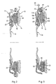
- the clutch comprises a reaction plate 13 intended to be wedged in rotation on a driving shaft, here the crankshaft of a combustion engine of a motor vehicle, a friction disk 14 bearing at its outer periphery friction linings 15 and intended to be set in rotation on a driven shaft.
- a cover 11 is fixed on the reaction plate 13 and elastic means with axial action, here a diaphragm 16, acts between the cover 11 and a pressure plate 12 integral in rotation with the cover 11 but can move axially relative to it , the diaphragm 16 applying, by pressing on the cover 11, the pressure plate 12 against the friction disc 14 so that the friction linings 15 are clamped between the pressure plates 12 and reaction 13; as known per se, the diaphragm 16 is hingedly mounted on the cover 11 by fasteners 21 riveted thereon and bears on the cover in a circumferential range 20 that it has.
- the pressure plate 12 consists of two half-trays; a half-plate 12A said outer half-plate, and a half-plate 12B, said inner half-plate, which directly faces the friction disc 14; tangential tongues conventionally connect the inner half-plate 12B to the lid 11, for connection, with axial mobility, of the pressure plate 12 with the lid 11.
- the two half-plates 12A, 12B are integral in rotation with the drive shaft but axially movable relative to each other, under the action of a backlash device due to wear.
- the backlash device comprises complementary ramps 17, 18 arranged circumferentially and respectively associated with each of the two half-plates 12A, 12B.
- the outer half-plate 12A is an annular piece housed in line with a redent 25 of the inner half-plate 12B; the axial length of the annular piece 12A is greater than the axial height of the redent 25 and its end facing the lid 11 is shaped as a support bead 19 for the diaphragm 16.
- the annular piece 12A On its face turned towards the half-plate 12B, the annular piece 12A carries ramps 18, whose axis is the axis of the clutch and which constitute the adjustment ramp.
- the annular piece 12A constituting the outer half-plate cooperates with ramps 17, complementary ramps 18, made in the inner half-plate 12B and constituting the support ramp.
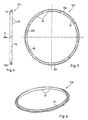
- a split segment 24 surrounds the redent 25 being disposed radially between said redent 25 and the half-plate 12A.
- the segment 24 is in one piece, of generally annular shape.
- the direction of the ramps 17 and adjustment 18 is such that, when the half-plate 12A is subjected to an acceleration in one direction, the adjustment ramp 18 moves in rotation relative to the support ramp 17 and the half-plate 12A, during this movement, advance axially relative to the inner half-plate 12B towards the cover 11, said direction having been chosen accordingly; thus, the acyclism of the heat engine is sufficient to axially out the outer half-plate 12A relative to the redent 25 if, of course, nothing opposes this output, as explained below.
- the backlash device also comprises a trigger consisting of at least one radial split elastic pin 22 introduced into a passage 28 which it passes through formed in a radial end lug 29 of the inner half-plate 12B; the diameter of the passage 28 is smaller than the outer diameter of the pin 22 in the free state so that it is frictionally mounted in the passage 28 and immobilized axially relative to the inner half-plate 12B; this immobilization friction is provided of a value such that it can be overcome by the axial force due to the diaphragm 16 and that it can not be overcome by the return force to which the pressure plate 12 is subjected, return force such as that usually coming from the tangential tongues rotatably coupling said pressure plate 12, here the half tray 12B, and the lid 11.
- three pins such as the pin 22 are provided, introduced into three passages 28 formed in three legs 29 of the inner half-plate 12B.
- Figures 2 and 3 show the engaged clutch, the friction linings 15 being new and clamped between the pressure plate 12 and the reaction plate 13.
- the pin 22 came into abutment on the cover 11, then the diaphragm continued its travel and took off from the support cord 19; since the internal half-plate 12B has only moved back by an amount equal to the clearance 26, the shoulder 19A of the support bead 19 is at a distance from the abutment cover 11A corresponding to the measured wear axially; in a second step, the outer half-plate 12A, which is no longer subjected to the action of the diaphragm, is free to move towards the diaphragm 16, thanks to the acceleration to which it is subjected due to the acyclism of the motor, as explained above; the output of the outer half-plate 12A continues until abutting the shoulder 19A of the support bead 19 on the cover abutment 11A: thus, the play due to wear has been caught.
- control means comprise a lever 30 rotatably mounted around a rotation means carried here by the inner half-plate 12B; in the form shown, the means of rotation is an axle 31 provided, on the one hand, with a head 32 holding said lever 30 axially and on the other hand with a shank 33 by which it is subjected to said half plate 12B, for example by riveting.
- the portion of the lever 30 which extends radially outwardly beyond the axis 31 is disposed in line with the slot of the split segment 24; so that this part, said active part 32 of the lever 30, can be made to expand said segment 24, under certain conditions, the ends of the split segment 24, which define its slot, have a significant radial extension, much greater than the thickness radial from the rest of the body of segment 24; here, this radial extension is obtained by pads 33, 34 attached to the ends of the segment 24, for example by welding or overmolding.
- the pads 33, 34 are arranged in a notch 23 of the inner half-plate 12B.
- a spring 35 is disposed in the notch 23 and is adapted to bias the segment 24 by means of one of the pads, here the pad 33, in a direction of rotation, here the opposite direction of that clockwise.
- the spring 35 avoids for example an over-catch when starting an engine equipped with a double damping flywheel, which, as we know, for a speed below the idle speed, is subject to phenomena of resonance leading to strong accelerations.
- the setting of the spring 35 must of course take into account the reduction effect due to the driving of the split segment 24 by the active portion 32 of the lever 30, while it moves the edges of the slot of the segment 24; this Reduction effect leads to a low expansion of the segment 24, given its circumferential movement, so a significant effort.
- the ends of the segment 24 which border its slot have a sufficient radial height obtained by bringing back pads 33, 34 for cooperation with the active part 32 of the lever 30.
- This sufficient height can be obtained otherwise, for example by appropriately shaping the ends of the segment itself.
- FIG. 9 An example is shown in Figure 9; here, the ends of a segment 124 have been folded to form loops 133, 134 having parallel straight portions 135, 136 defining the slot of the split segment 124.
- the split segment 124 internally carries radial pins 137, here four pins 137, intended to be received in an external groove or groove of the half-plate 12B for axial retention.
- segment shown in FIG. 10 is similar to segment 124 of FIG. 9 except that here it is in two parts 131, 132 stapled at 138.
- Figures 11 and 12 show a variant of control means in the form of a lever.
- the bottom of the notch 23 communicates by a radial channel 38 with an opposite notch 37, the bottom of which constitutes a seat for a shank 231 of a lever 230 whose active part 232, resulting from the shank 231, is here of parallelepipedal shape and passes through the radial channel 38; advantageously, the tail 231 cooperates with said seat according to a cylindrical or spherical bearing, which seat may have a shape complementary to that of this scope.
- the active portion 232 of the lever 230 is received in grooves 235, 236 formed at the end of the portions 233, 234 of the segment 224.
Landscapes
- Engineering & Computer Science (AREA)
- General Engineering & Computer Science (AREA)
- Mechanical Engineering (AREA)
- Mechanical Operated Clutches (AREA)
- Braking Arrangements (AREA)
- Connection Of Motors, Electrical Generators, Mechanical Devices, And The Like (AREA)
- Hydraulic Clutches, Magnetic Clutches, Fluid Clutches, And Fluid Joints (AREA)
Claims (19)
- Reibungskupplung für ein Kraftfahrzeug mit Verbrennungsmotor, umfassend eine Gegendruckplatte (13), die dazu bestimmt ist, drehfest an einer Antriebswelle angebracht zu werden, eine Reibscheibe (14), die an ihrem Außenumfang mit Reibbelägen (15) versehen ist und die dazu bestimmt ist, drehfest an einer Abtriebswelle angebracht zu werden, eine Druckplatte (12), einen an der Gegendruckplatte (13) befestigten Deckel (11), axial wirkende elastische Mittel (16), die zwischen dem Deckel (11) und der Druckplatte (12) wirken, wobei die Druckplatte (12) drehfest mit dem Deckel (11) verbunden ist und sich dabei bezüglich des Deckels axial verschieben kann, wobei eines der Teile, die Gegendruckplatte (13) oder die Druckplatte (12) oder der Deckel (11), aus zwei Teilehälften besteht, die unter der Wirkung einer Vorrichtung zum Ausgleich des auf den Verschleiß zurückzuführenden Spiels in Axialrichtung zueinander verschiebbar sind, wobei die Spielausgleichsvorrichtung mindestens ein Paar komplementärer Rampen (17, 18) umfasst, die umfangsmäßig angeordnet jeweils einer der beiden Teilehälften (12A, 12B) axial zugeordnet sind, wobei eine der Rampen (17) so ausgeführt ist, dass sie sich bezüglich der anderen Rampe (18) in Richtung der Vergrößerung der Gesamtdicke des Teils, der sogenannten Ausgleichsrichtung, umfangsgemäß bewegen kann, und durch eine sogenannte Rücklaufsperre (24, 124, 224) daran gehindert wird, sich in die andere Richtung zu bewegen, wobei die Umfangs-Bewegung durch einen auf den Verschleißzustand reagierenden Auslöser (22) aktiviert wird, wobei eine der Rampen (18) am Umfang eines Trägheitsteils (12A) ausgebildet ist, so dass der Azyklismus des Verbrennungsmotors des Kraftfahrzeugs dazu ausgenutzt wird, die umfangsgemäße Relativbewegung der komplementären Rampen in Spielausgleichsrichtung zu bewirken, wobei die Kupplung Steuermittel enthält, die so ausgeführt sind, dass sie die Spielausgleichsvorrichtung steuern, indem sie ihren Betrieb gestatten oder nicht gestatten, wobei es sich bei der Rücklaufsperre (24, 124, 224) um ein geteiltes Segment (24, 124, 224) handelt, das mit dem Teil (12) drehfest verbunden ist, und die auf Beschleunigung reagierenden Steuermittel einen allgemein radial angeordneten Hebel (30, 230) umfassen, dessen Ende sich zwischen den Enden des Sprengrings (24, 124, 224) befindet und der zum Aufweiten des geteilten Segments (24, 124, 224) ausgeführt ist, wobei der Hebel (30, 230) drehbar an dem Teil (12) so angebracht ist, dass er gegenüber der Zentrifugalkraft in radialer Richtung festgehalten wird.
- Kupplung nach Anspruch 1, dadurch gekennzeichnet, dass das Teil eine der beiden Platten, Gegendruckplatte (13) oder Druckplatte (12), als sogenannte erste Platte ist, die aus zwei Plattenhälften besteht, einer sogenannten äußeren Plattenhälfte (12A) und einer sogenannten inneren Plattenhälfte (12B), wobei die innere Plattenhälfte (12B) jene ist, die einem Reibbelag gegenüberliegt und damit zusammenwirken soll, wobei die beiden Plattenhälften (12A, 12B) drehfest mit der Antriebswelle verbunden sind, sich aber unter der Wirkung der Spielausgleichsvorrichtung relativ zueinander in Axialrichtung verschieben können, wobei eine der Rampen (17), die sogenannte Stützrampe, mit einer (12B) der Plattenhälften drehfest verbunden ist und die andere Rampe (18), die sogenannte Einstellrampe so ausgeführt ist, dass sie sich bezüglich der Stützrampe (17) in Richtung der Vergrößerung der Gesamtdicke der ersten Platte umfangsgemäß bewegen kann.
- Kupplung nach Anspruch 2, dadurch gekennzeichnet, dass die Stützrampe (17) von der inneren Plattenhälfte (12B) getragen ist.
- Kupplung nach Anspruch 2 oder 3, dadurch gekennzeichnet, dass die Einstellrampe (18) von der äußeren Plattenhälfte (12A) getragen wird.
- Kupplung nach einem der Ansprüche 1 bis 3, dadurch gekennzeichnet, dass es sich bei der ersten Platte um die Druckplatte (12) handelt.
- Kupplung nach den Ansprüchen 3 und 4, bei der die axial wirkenden elastischen Mittel (16) aus einer Federscheibe bestehen, dadurch gekennzeichnet, dass die äußere Plattenhälfte (12A) mit einem Stützstreifen (19) für die Federscheibe versehen ist.
- Kupplung nach einem der Ansprüche 2 bis 6, dadurch gekennzeichnet, dass die Einstellrampe (18) eine Reihe von Rampen umfasst, die sich am Rand eines ringförmigen, gestanzten und gebogenen Blechteils (12A), das die äußere Plattenhälfte bildet, um den Umfang erstrecken.
- Kupplung nach einem der Ansprüche 1 bis 7, dadurch gekennzeichnet, dass der Hebel (30, 230) einen sogenannten aktiven Teil (32, 232) umfasst, der am Schlitz des geteilten Segments (124, 224) angeordnet ist.
- Kupplung nach einem der Ansprüche 1 bis 8, dadurch gekennzeichnet, dass die Enden (33, 133, 233 - 34, 134, 234) des geteilten Segments (24, 124, 224), die seinen Schlitz definieren, eine radiale Aufweitung aufweisen.
- Kupplung nach Anspruch 9, dadurch gekennzeichnet, dass die radiale Aufweitung durch an den Enden des Segments (24, 224) befestigte Schuhe (33, 233 - 34, 234) erhalten wird.
- Kupplung nach Anspruch 9, dadurch gekennzeichnet, dass die radiale Ausweitung durch eine schlaufenförmige Konfiguration (133, 134) der Enden des Segments (124) erhalten wird.
- Kupplung nach einem der Ansprüche 9 bis 11, dadurch gekennzeichnet, dass das Segment (124) aus einem einzigen Teil besteht.
- Kupplung nach einem der Ansprüche 9 bis 11, dadurch gekennzeichnet, dass das Segment (124) aus zwei zusammengehefteten (138) Teilen (131, 132) besteht.
- Kupplung nach einem der Ansprüche 9 bis 13, dadurch gekennzeichnet, dass das geteilte Segment (124) axial festgehalten wird.
- Kupplung nach Anspruch 14, dadurch gekennzeichnet, dass das axiale Festhalten des geteilten Segments (124) durch radiale Stifte (137) erfolgt, mit denen es innen versehen ist und die in einer äußeren Auskehlung oder Nut aufgenommen werden.
- Kupplung nach einem der Ansprüche 1 bis 15, dadurch gekennzeichnet, dass das geteilte Segment (24, 124, 224) umfangsmäßig in einer Drehrichtung elastisch beansprucht (35) ist.
- Kupplung nach einem der Ansprüche 1 bis 16, dadurch gekennzeichnet, dass es sich bei dem Drehungsmittel um eine Achse (31) handelt.
- Kupplung nach einem der Ansprüche 1 bis 16, dadurch gekennzeichnet, dass es sich bei dem Drehungsmittel um ein Gelenk (231) handelt.
- Kupplung nach Anspruch 18, dadurch gekennzeichnet, dass zum axialen Festhalten des Hebels (230) sein aktiver Teil (232) in an den Enden des Segments (224) ausgebildeten radialen Nuten (235, 236) aufgenommen ist.
Applications Claiming Priority (3)
| Application Number | Priority Date | Filing Date | Title |
|---|---|---|---|
| FR0113701 | 2001-10-23 | ||
| FR0113701A FR2831233B1 (fr) | 2001-10-23 | 2001-10-23 | Embrayage a friction, pour vehicule automobile, equipe d'un dispositif de rattrapage de jeu pilote |
| PCT/FR2002/003348 WO2003036116A2 (fr) | 2001-10-23 | 2002-10-02 | Embrayage a friction, pour vehicule automobile, equipe d'un dispositif de rattrapage de jeu pilote |
Publications (2)
| Publication Number | Publication Date |
|---|---|
| EP1438516A2 EP1438516A2 (de) | 2004-07-21 |
| EP1438516B1 true EP1438516B1 (de) | 2007-04-04 |
Family
ID=8868635
Family Applications (1)
| Application Number | Title | Priority Date | Filing Date |
|---|---|---|---|
| EP02801929A Expired - Lifetime EP1438516B1 (de) | 2001-10-23 | 2002-10-02 | Reibungskupplung mit gesteuerter nachstellvorrichtung, insbesondere für kraftfahrzeuge |
Country Status (10)
| Country | Link |
|---|---|
| US (1) | US6957729B2 (de) |
| EP (1) | EP1438516B1 (de) |
| KR (1) | KR100910371B1 (de) |
| CN (1) | CN1325814C (de) |
| AT (1) | ATE358785T1 (de) |
| BR (1) | BR0206163B1 (de) |
| DE (1) | DE60219339T2 (de) |
| FR (1) | FR2831233B1 (de) |
| MX (1) | MXPA04003775A (de) |
| WO (1) | WO2003036116A2 (de) |
Families Citing this family (21)
| Publication number | Priority date | Publication date | Assignee | Title |
|---|---|---|---|---|
| DE10247013A1 (de) * | 2002-10-09 | 2004-04-22 | Zf Sachs Ag | Druckplattenbaugruppe für eine Reibungskupplung |
| DE502005000756D1 (de) * | 2004-02-24 | 2007-07-12 | Luk Lamellen & Kupplungsbau | Selbstnachstellende Kupplung |
| ATE448417T1 (de) * | 2005-04-08 | 2009-11-15 | Luk Lamellen & Kupplungsbau | Reibungskupplung |
| CN101523071B (zh) * | 2006-10-06 | 2011-07-20 | 卢克摩擦片和离合器两合公司 | 自补偿调节的摩擦离合器 |
| EP1972816B1 (de) * | 2007-03-22 | 2011-07-13 | Schaeffler Technologies AG & Co. KG | Selbstnachstellende Reibungskupplung sowie Doppelkupplung mit einer solchen Reibungskupplung |
| EP1972815B1 (de) * | 2007-03-22 | 2012-06-27 | Schaeffler Technologies AG & Co. KG | Antriebsfeder für eine Tellerfederhebelbaugruppe zum Betätigen einer Reibungskupplung mit integriertem Verschleißausgleich sowie Tellerfederhebelbaugruppe |
| DE102009007828B4 (de) * | 2008-03-03 | 2018-08-09 | Schaeffler Technologies AG & Co. KG | Reibungskupplung |
| WO2010057468A2 (de) * | 2008-11-24 | 2010-05-27 | Luk Lamellen Und Kupplungsbau Beteiligungs Kg | Anlasserscheibe mit rutschkupplung |
| JP4967051B2 (ja) * | 2010-08-20 | 2012-07-04 | 株式会社エクセディ | クラッチカバー組立体 |
| WO2012065589A1 (de) * | 2010-11-19 | 2012-05-24 | Schaeffler Technologies AG & Co. KG | Nachstelleinrichtung |
| WO2012142990A1 (de) * | 2011-04-21 | 2012-10-26 | Schaeffler Technologies AG & Co. KG | Nachstelleinrichtung für eine reibungskupplung |
| JP6173319B2 (ja) * | 2011-08-24 | 2017-08-02 | シェフラー テクノロジーズ アー・ゲー ウント コー. カー・ゲーSchaeffler Technologies AG & Co. KG | クラッチ装置 |
| FR2982332B1 (fr) * | 2011-11-08 | 2013-11-22 | Valeo Embrayages | Ensemble de transmission de couple, en particulier pour vehicule automobile |
| WO2014153558A1 (en) * | 2013-03-22 | 2014-09-25 | Eaton Corporation | Cam hard stop for end of life |
| WO2015142545A1 (en) * | 2014-03-18 | 2015-09-24 | Schaeffler Technologies AG & Co. KG | Improved adjustment tab for an adjustment means of a self-adjusting clutch and a clutch assembly comprising the improved adjustment tab |
| US9476462B2 (en) * | 2014-04-23 | 2016-10-25 | Schaeffler Technologies AG & Co. KG | Clutch with wire pivot ring having straight sections |
| CN108368894B (zh) * | 2015-11-25 | 2020-11-10 | 敏思工业公司 | 与可控连接组件一起使用的机电装置以及连接和机电控制组件 |
| US10132364B2 (en) | 2016-07-29 | 2018-11-20 | GM Global Technology Operations LLC | Backing plate providing axial stiffness |
| US10215237B2 (en) | 2016-07-29 | 2019-02-26 | GM Global Technology Operations LLC | Multiple-piece backing plate having parts made of different materials |
| FR3092883B1 (fr) | 2019-02-19 | 2021-05-07 | Valeo Embrayages | Mecanisme d’embrayage a rattrapage d’usure |
| CN112607552B (zh) * | 2020-12-18 | 2022-04-05 | 亿涛建设集团有限公司 | 多重防坠起重机构 |
Family Cites Families (5)
| Publication number | Priority date | Publication date | Assignee | Title |
|---|---|---|---|---|
| US4207972A (en) | 1978-05-26 | 1980-06-17 | Borg-Warner Corporation | Automatic wear compensator for Belleville spring clutches |
| JP2517821B2 (ja) * | 1992-07-23 | 1996-07-24 | 株式会社エクセディ | フライホイ―ル組立体 |
| US5641048A (en) * | 1994-11-14 | 1997-06-24 | Luk Lamellen Und Kupplungsbau Gmbh | Friction clutch |
| FR2750467B1 (fr) | 1996-06-27 | 1998-08-14 | Valeo | Embrayage a friction a dispositif de rattrapage de jeu pour vehicule automobile |
| FR2809147B1 (fr) * | 2000-05-19 | 2002-09-06 | Valeo | Embrayage a friction a dispositif de rattrapage de jeu pilote pour vehicule automobile |
-
2001
- 2001-10-23 FR FR0113701A patent/FR2831233B1/fr not_active Expired - Fee Related
-
2002
- 2002-10-02 KR KR1020047005634A patent/KR100910371B1/ko not_active Expired - Lifetime
- 2002-10-02 EP EP02801929A patent/EP1438516B1/de not_active Expired - Lifetime
- 2002-10-02 BR BRPI0206163-5A patent/BR0206163B1/pt not_active IP Right Cessation
- 2002-10-02 MX MXPA04003775A patent/MXPA04003775A/es active IP Right Grant
- 2002-10-02 WO PCT/FR2002/003348 patent/WO2003036116A2/fr not_active Ceased
- 2002-10-02 AT AT02801929T patent/ATE358785T1/de not_active IP Right Cessation
- 2002-10-02 US US10/466,910 patent/US6957729B2/en not_active Expired - Lifetime
- 2002-10-02 CN CNB028032675A patent/CN1325814C/zh not_active Expired - Lifetime
- 2002-10-02 DE DE60219339T patent/DE60219339T2/de not_active Expired - Lifetime
Non-Patent Citations (1)
| Title |
|---|
| None * |
Also Published As
| Publication number | Publication date |
|---|---|
| KR100910371B1 (ko) | 2009-08-03 |
| CN1549904A (zh) | 2004-11-24 |
| EP1438516A2 (de) | 2004-07-21 |
| CN1325814C (zh) | 2007-07-11 |
| DE60219339T2 (de) | 2007-12-13 |
| FR2831233B1 (fr) | 2004-01-16 |
| BR0206163B1 (pt) | 2011-04-05 |
| KR20040045849A (ko) | 2004-06-02 |
| ATE358785T1 (de) | 2007-04-15 |
| MXPA04003775A (es) | 2004-07-30 |
| US6957729B2 (en) | 2005-10-25 |
| WO2003036116A2 (fr) | 2003-05-01 |
| DE60219339D1 (de) | 2007-05-16 |
| WO2003036116A3 (fr) | 2004-02-12 |
| US20040079607A1 (en) | 2004-04-29 |
| FR2831233A1 (fr) | 2003-04-25 |
| BR0206163A (pt) | 2003-10-28 |
Similar Documents
| Publication | Publication Date | Title |
|---|---|---|
| EP1438516B1 (de) | Reibungskupplung mit gesteuerter nachstellvorrichtung, insbesondere für kraftfahrzeuge | |
| EP0015204B1 (de) | Vorrichtung zur Dämpfung von Drehschwingungen, insbesondere Kupplungsscheibe für Kraftfahrzeug | |
| EP0923679B1 (de) | Reibungskupplung für kraftfahrzeuge mit verschleiss-nachstelleinrichtung | |
| FR2726872A1 (fr) | Embrayage a friction a compensation automatique d'usure | |
| WO2001088400A1 (fr) | Embrayage a friction a dispositif de rattrapage de jeu pilote pour vehicule automobile | |
| EP0857263A1 (de) | Reibungskupplung für kraftfahrzeuge mit einer verschleiss-nachstelleinrichtung | |
| EP0917629B1 (de) | Reibungskupplung mit einer verschleiss-nachstelleinrichtung insbesondere für kraftfahrzeuge | |
| EP0720702B1 (de) | Kupplung mit nachstellvorrichtung, insbesondere für kraftfahrzeuge | |
| EP0857262B1 (de) | Reibungskupplung für kraftfahrzeuge mit einer verschleiss-nachstelleinrichtung | |
| EP0910753A1 (de) | Kupplungsmechanismus mit geringem lösekraftbedarf für eine kraftfahrzeug-reibkupplung | |
| WO2000028229A1 (fr) | Embrayage a friction a dispositif de rattrapage d'usure des garnitures de friction, en particulier pour vehicule automobile, equipe de moyens d'information du degre de ladite usure | |
| FR2804186A1 (fr) | Embrayage a friction a dispositif de rattrapage d'usure des garnitures de frictions, notamment pour vehicule automobile | |
| WO2000039474A1 (fr) | Embrayage a friction a dispositif de rattrapage d'usure des garnitures de friction, en particulier pour vehicule automobile | |
| EP0916035A1 (de) | Reibungskupplung mit nachstellvorrichtung mit rücksetzmitteln und zughöriges werkzeug | |
| EP0975884A1 (de) | Kupplungsmechanismus für ein kraftfahrzeug, mit einer verschleiss-nachstelleinrichtung für die reibbeläge | |
| WO1997001043A1 (fr) | Embrayage a friction a dispositif de rattrapage de jeu, notamment pour vehicule automobile | |
| EP1082549B1 (de) | Reibungskupplung mit einer verschleiss-nachstelleinrichtung ,insbesondere für kraftfahrzeuge | |
| FR2749893A1 (fr) | Ensemble formant carter d'embrayage | |
| FR2750467A1 (fr) | Embrayage a friction a dispositif de rattrapage de jeu pour vehicule automobile | |
| FR2733808A1 (fr) | Embrayage a friction a rattrapage d'usure | |
| FR2661721A1 (fr) | Embrayage autonome a friction avec disque mene a faible inertie. | |
| FR2613446A1 (fr) | Dispositif amortisseur de torsion a organe de transmission de mouvement | |
| FR2765289A1 (fr) | Embrayage a friction a dispositif de rattrapage d'usure des garnitures de friction, en particulier pour vehicule automobile | |
| FR2801356A1 (fr) | Dispositif a volant d'inertie, en particulier pour embrayage | |
| FR3092883A1 (fr) | Mecanisme d’embrayage a rattrapage d’usure |
Legal Events
| Date | Code | Title | Description |
|---|---|---|---|
| PUAI | Public reference made under article 153(3) epc to a published international application that has entered the european phase |
Free format text: ORIGINAL CODE: 0009012 |
|
| 17P | Request for examination filed |
Effective date: 20040331 |
|
| AK | Designated contracting states |
Kind code of ref document: A2 Designated state(s): AT BE BG CH CY CZ DE DK EE ES FI FR GB GR IE IT LI LU MC NL PT SE SK TR |
|
| AX | Request for extension of the european patent |
Extension state: AL LT LV MK RO SI |
|
| GRAP | Despatch of communication of intention to grant a patent |
Free format text: ORIGINAL CODE: EPIDOSNIGR1 |
|
| GRAS | Grant fee paid |
Free format text: ORIGINAL CODE: EPIDOSNIGR3 |
|
| GRAA | (expected) grant |
Free format text: ORIGINAL CODE: 0009210 |
|
| AK | Designated contracting states |
Kind code of ref document: B1 Designated state(s): AT BE BG CH CY CZ DE DK EE ES FI FR GB GR IE IT LI LU MC NL PT SE SK TR |
|
| PG25 | Lapsed in a contracting state [announced via postgrant information from national office to epo] |
Ref country code: FI Free format text: LAPSE BECAUSE OF FAILURE TO SUBMIT A TRANSLATION OF THE DESCRIPTION OR TO PAY THE FEE WITHIN THE PRESCRIBED TIME-LIMIT Effective date: 20070404 |
|
| REG | Reference to a national code |
Ref country code: GB Ref legal event code: FG4D Free format text: NOT ENGLISH |
|
| REG | Reference to a national code |
Ref country code: CH Ref legal event code: EP |
|
| REF | Corresponds to: |
Ref document number: 60219339 Country of ref document: DE Date of ref document: 20070516 Kind code of ref document: P |
|
| REG | Reference to a national code |
Ref country code: IE Ref legal event code: FG4D Free format text: LANGUAGE OF EP DOCUMENT: FRENCH |
|
| PG25 | Lapsed in a contracting state [announced via postgrant information from national office to epo] |
Ref country code: SE Free format text: LAPSE BECAUSE OF FAILURE TO SUBMIT A TRANSLATION OF THE DESCRIPTION OR TO PAY THE FEE WITHIN THE PRESCRIBED TIME-LIMIT Effective date: 20070704 |
|
| PG25 | Lapsed in a contracting state [announced via postgrant information from national office to epo] |
Ref country code: ES Free format text: LAPSE BECAUSE OF FAILURE TO SUBMIT A TRANSLATION OF THE DESCRIPTION OR TO PAY THE FEE WITHIN THE PRESCRIBED TIME-LIMIT Effective date: 20070715 |
|
| PG25 | Lapsed in a contracting state [announced via postgrant information from national office to epo] |
Ref country code: PT Free format text: LAPSE BECAUSE OF FAILURE TO SUBMIT A TRANSLATION OF THE DESCRIPTION OR TO PAY THE FEE WITHIN THE PRESCRIBED TIME-LIMIT Effective date: 20070904 |
|
| NLV1 | Nl: lapsed or annulled due to failure to fulfill the requirements of art. 29p and 29m of the patents act | ||
| GBV | Gb: ep patent (uk) treated as always having been void in accordance with gb section 77(7)/1977 [no translation filed] |
Effective date: 20070404 |
|
| PG25 | Lapsed in a contracting state [announced via postgrant information from national office to epo] |
Ref country code: AT Free format text: LAPSE BECAUSE OF FAILURE TO SUBMIT A TRANSLATION OF THE DESCRIPTION OR TO PAY THE FEE WITHIN THE PRESCRIBED TIME-LIMIT Effective date: 20070404 |
|
| REG | Reference to a national code |
Ref country code: IE Ref legal event code: FD4D |
|
| PG25 | Lapsed in a contracting state [announced via postgrant information from national office to epo] |
Ref country code: CZ Free format text: LAPSE BECAUSE OF FAILURE TO SUBMIT A TRANSLATION OF THE DESCRIPTION OR TO PAY THE FEE WITHIN THE PRESCRIBED TIME-LIMIT Effective date: 20070404 Ref country code: DK Free format text: LAPSE BECAUSE OF FAILURE TO SUBMIT A TRANSLATION OF THE DESCRIPTION OR TO PAY THE FEE WITHIN THE PRESCRIBED TIME-LIMIT Effective date: 20070404 Ref country code: BG Free format text: LAPSE BECAUSE OF FAILURE TO SUBMIT A TRANSLATION OF THE DESCRIPTION OR TO PAY THE FEE WITHIN THE PRESCRIBED TIME-LIMIT Effective date: 20070704 Ref country code: NL Free format text: LAPSE BECAUSE OF FAILURE TO SUBMIT A TRANSLATION OF THE DESCRIPTION OR TO PAY THE FEE WITHIN THE PRESCRIBED TIME-LIMIT Effective date: 20070404 Ref country code: IE Free format text: LAPSE BECAUSE OF FAILURE TO SUBMIT A TRANSLATION OF THE DESCRIPTION OR TO PAY THE FEE WITHIN THE PRESCRIBED TIME-LIMIT Effective date: 20070404 |
|
| PLBE | No opposition filed within time limit |
Free format text: ORIGINAL CODE: 0009261 |
|
| STAA | Information on the status of an ep patent application or granted ep patent |
Free format text: STATUS: NO OPPOSITION FILED WITHIN TIME LIMIT |
|
| 26N | No opposition filed |
Effective date: 20080107 |
|
| BERE | Be: lapsed |
Owner name: VALEO EMBRAYAGES Effective date: 20071031 |
|
| PG25 | Lapsed in a contracting state [announced via postgrant information from national office to epo] |
Ref country code: GB Free format text: LAPSE BECAUSE OF FAILURE TO SUBMIT A TRANSLATION OF THE DESCRIPTION OR TO PAY THE FEE WITHIN THE PRESCRIBED TIME-LIMIT Effective date: 20070404 Ref country code: GR Free format text: LAPSE BECAUSE OF FAILURE TO SUBMIT A TRANSLATION OF THE DESCRIPTION OR TO PAY THE FEE WITHIN THE PRESCRIBED TIME-LIMIT Effective date: 20070705 Ref country code: IT Free format text: LAPSE BECAUSE OF FAILURE TO SUBMIT A TRANSLATION OF THE DESCRIPTION OR TO PAY THE FEE WITHIN THE PRESCRIBED TIME-LIMIT Effective date: 20070404 |
|
| PG25 | Lapsed in a contracting state [announced via postgrant information from national office to epo] |
Ref country code: MC Free format text: LAPSE BECAUSE OF NON-PAYMENT OF DUE FEES Effective date: 20071031 |
|
| REG | Reference to a national code |
Ref country code: CH Ref legal event code: PL |
|
| PG25 | Lapsed in a contracting state [announced via postgrant information from national office to epo] |
Ref country code: LI Free format text: LAPSE BECAUSE OF NON-PAYMENT OF DUE FEES Effective date: 20071031 Ref country code: CH Free format text: LAPSE BECAUSE OF NON-PAYMENT OF DUE FEES Effective date: 20071031 |
|
| PG25 | Lapsed in a contracting state [announced via postgrant information from national office to epo] |
Ref country code: BE Free format text: LAPSE BECAUSE OF NON-PAYMENT OF DUE FEES Effective date: 20071031 |
|
| PG25 | Lapsed in a contracting state [announced via postgrant information from national office to epo] |
Ref country code: EE Free format text: LAPSE BECAUSE OF FAILURE TO SUBMIT A TRANSLATION OF THE DESCRIPTION OR TO PAY THE FEE WITHIN THE PRESCRIBED TIME-LIMIT Effective date: 20070404 |
|
| PG25 | Lapsed in a contracting state [announced via postgrant information from national office to epo] |
Ref country code: CY Free format text: LAPSE BECAUSE OF FAILURE TO SUBMIT A TRANSLATION OF THE DESCRIPTION OR TO PAY THE FEE WITHIN THE PRESCRIBED TIME-LIMIT Effective date: 20070404 |
|
| PG25 | Lapsed in a contracting state [announced via postgrant information from national office to epo] |
Ref country code: LU Free format text: LAPSE BECAUSE OF NON-PAYMENT OF DUE FEES Effective date: 20071002 |
|
| REG | Reference to a national code |
Ref country code: FR Ref legal event code: PLFP Year of fee payment: 14 |
|
| REG | Reference to a national code |
Ref country code: FR Ref legal event code: PLFP Year of fee payment: 15 |
|
| REG | Reference to a national code |
Ref country code: FR Ref legal event code: PLFP Year of fee payment: 16 |
|
| REG | Reference to a national code |
Ref country code: FR Ref legal event code: PLFP Year of fee payment: 17 |
|
| PGFP | Annual fee paid to national office [announced via postgrant information from national office to epo] |
Ref country code: SK Payment date: 20180917 Year of fee payment: 17 Ref country code: TR Payment date: 20180926 Year of fee payment: 17 |
|
| PGFP | Annual fee paid to national office [announced via postgrant information from national office to epo] |
Ref country code: DE Payment date: 20181009 Year of fee payment: 17 |
|
| PGFP | Annual fee paid to national office [announced via postgrant information from national office to epo] |
Ref country code: FR Payment date: 20181030 Year of fee payment: 17 |
|
| REG | Reference to a national code |
Ref country code: DE Ref legal event code: R119 Ref document number: 60219339 Country of ref document: DE |
|
| REG | Reference to a national code |
Ref country code: SK Ref legal event code: MM4A Ref document number: E 2143 Country of ref document: SK Effective date: 20191002 |
|
| PG25 | Lapsed in a contracting state [announced via postgrant information from national office to epo] |
Ref country code: DE Free format text: LAPSE BECAUSE OF NON-PAYMENT OF DUE FEES Effective date: 20200501 |
|
| PG25 | Lapsed in a contracting state [announced via postgrant information from national office to epo] |
Ref country code: SK Free format text: LAPSE BECAUSE OF NON-PAYMENT OF DUE FEES Effective date: 20191002 |
|
| PG25 | Lapsed in a contracting state [announced via postgrant information from national office to epo] |
Ref country code: FR Free format text: LAPSE BECAUSE OF NON-PAYMENT OF DUE FEES Effective date: 20191031 |
|
| PG25 | Lapsed in a contracting state [announced via postgrant information from national office to epo] |
Ref country code: TR Free format text: LAPSE BECAUSE OF NON-PAYMENT OF DUE FEES Effective date: 20191002 |