EP1438603B1 - Technique de fusion de donnees de plusieurs detecteurs - Google Patents
Technique de fusion de donnees de plusieurs detecteurs Download PDFInfo
- Publication number
- EP1438603B1 EP1438603B1 EP02806775.9A EP02806775A EP1438603B1 EP 1438603 B1 EP1438603 B1 EP 1438603B1 EP 02806775 A EP02806775 A EP 02806775A EP 1438603 B1 EP1438603 B1 EP 1438603B1
- Authority
- EP
- European Patent Office
- Prior art keywords
- sensor
- probability
- sub
- performance characteristics
- sensors
- Prior art date
- Legal status (The legal status is an assumption and is not a legal conclusion. Google has not performed a legal analysis and makes no representation as to the accuracy of the status listed.)
- Expired - Lifetime
Links
Images


Classifications
-
- G—PHYSICS
- G08—SIGNALLING
- G08G—TRAFFIC CONTROL SYSTEMS
- G08G5/00—Traffic control systems for aircraft
- G08G5/70—Arrangements for monitoring traffic-related situations or conditions
- G08G5/72—Arrangements for monitoring traffic-related situations or conditions for monitoring traffic
- G08G5/723—Arrangements for monitoring traffic-related situations or conditions for monitoring traffic from the aircraft
-
- G—PHYSICS
- G01—MEASURING; TESTING
- G01S—RADIO DIRECTION-FINDING; RADIO NAVIGATION; DETERMINING DISTANCE OR VELOCITY BY USE OF RADIO WAVES; LOCATING OR PRESENCE-DETECTING BY USE OF THE REFLECTION OR RERADIATION OF RADIO WAVES; ANALOGOUS ARRANGEMENTS USING OTHER WAVES
- G01S13/00—Systems using the reflection or reradiation of radio waves, e.g. radar systems; Analogous systems using reflection or reradiation of waves whose nature or wavelength is irrelevant or unspecified
- G01S13/88—Radar or analogous systems specially adapted for specific applications
- G01S13/91—Radar or analogous systems specially adapted for specific applications for traffic control
-
- G—PHYSICS
- G01—MEASURING; TESTING
- G01S—RADIO DIRECTION-FINDING; RADIO NAVIGATION; DETERMINING DISTANCE OR VELOCITY BY USE OF RADIO WAVES; LOCATING OR PRESENCE-DETECTING BY USE OF THE REFLECTION OR RERADIATION OF RADIO WAVES; ANALOGOUS ARRANGEMENTS USING OTHER WAVES
- G01S13/00—Systems using the reflection or reradiation of radio waves, e.g. radar systems; Analogous systems using reflection or reradiation of waves whose nature or wavelength is irrelevant or unspecified
- G01S13/66—Radar-tracking systems; Analogous systems
- G01S13/72—Radar-tracking systems; Analogous systems for two-dimensional [2D] tracking, e.g. combination of angle and range tracking, track-while-scan radar
- G01S13/723—Radar-tracking systems; Analogous systems for two-dimensional [2D] tracking, e.g. combination of angle and range tracking, track-while-scan radar by using numerical data
- G01S13/726—Multiple target tracking
-
- G—PHYSICS
- G01—MEASURING; TESTING
- G01S—RADIO DIRECTION-FINDING; RADIO NAVIGATION; DETERMINING DISTANCE OR VELOCITY BY USE OF RADIO WAVES; LOCATING OR PRESENCE-DETECTING BY USE OF THE REFLECTION OR RERADIATION OF RADIO WAVES; ANALOGOUS ARRANGEMENTS USING OTHER WAVES
- G01S17/00—Systems using the reflection or reradiation of electromagnetic waves other than radio waves, e.g. lidar systems
- G01S17/87—Combinations of systems using electromagnetic waves other than radio waves
-
- G—PHYSICS
- G01—MEASURING; TESTING
- G01S—RADIO DIRECTION-FINDING; RADIO NAVIGATION; DETERMINING DISTANCE OR VELOCITY BY USE OF RADIO WAVES; LOCATING OR PRESENCE-DETECTING BY USE OF THE REFLECTION OR RERADIATION OF RADIO WAVES; ANALOGOUS ARRANGEMENTS USING OTHER WAVES
- G01S7/00—Details of systems according to groups G01S13/00, G01S15/00, G01S17/00
- G01S7/003—Transmission of data between radar, sonar or lidar systems and remote stations
Definitions
- the present invention is related generally to a method and system for locating the position of, and tracking, objects. More specifically, the invention is directed towards a method and system for locating and tracking airborne aircraft.
- the margin of error when applied to each quantitative and qualitative observation, results in the tracking system applying a larger than desirable separation zone around the best estimated aircraft location.
- This separation zone, or uncertainty zone is typically increased during foul weather in order to compensate for the performance characteristics of the sensors and the less than optimal reliability and accuracy of the data.
- TCAS Traffic Alert and Collision Avoidance System
- the TCAS relies on data transmitted by a transponder located on an aircraft. Since all aircraft are not mandated to have a transponder, the system can not be relied upon for maintaining minimum and safe separation zones.
- Other current methods collect data from several sources, and then report the location information either by applying a weighted average to the data, or relaying the data from a single sensor, or transmitting all information as separate attributes (e.g., speed, direction, altitude, etc.).
- the disclosed invention is a system to determine a most likely position of an object in a location space, said system comprising:
- Figure 1 is a conceptual drawing illustrating an object locator 10 in accordance with the present invention.
- Object locator 10 preferably fuses (or aggregates) inputs from a plurality of sensors and/or sources 12, 16,20, and 24 for locating and tracking the position of an object such as an airborne aircraft.
- sensors 12 and 20 may provide quantitative data and sources 16 and 24 may provide qualitative information.
- the term sensor is used to collectively represent sensors and/or sources.
- the four sensors 12, 16, 20, and 24 shown in Figure 1 are for illustration purposes only, and any number of sensors can be accommodated by the present invention.
- Sensors 12, 16, 20, and 24 scan for objects 1, 2, 3, 4, and 5, and provide information regarding the estimated positions of these objects to the object locator 10 along paths 14, 18, 22, and 26, respectively.
- the five objects 1, 2, 3, 4, and 5 shown in Figure 1 are for illustration purposes only, and any number of objects can be accommodated by the present invention.
- Typical sensor performance characteristics include information on the sensor's accuracy, reliability, effect of environmental conditions (e.g., temperature, pressure, precipitation, etc.), degradation with age, etc. This information may be stored in a database 28 accessible by the object locator 10 along path 29. Alternately, each sensor 12, 16, 20, and 24 may transmit its performance characteristic along with the estimated positions of the objects on its respective path 14, 18, 22, and 26 to object locator 10.
- Object locator 10 preferably uses statistical methods to conduct a probability analysis on the data to generate a value indicative of the most likely location of the object.
- object locator 10 may receive conflicting reports on the estimated position of the same identified object. Additionally, each reported position will likely have a level of uncertainty associated with it reflective of the performance characteristics of the corresponding sensor or sensors.
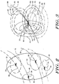
- Figure 2 wherein the four sensors of Figure 1 are shown reporting four distinctly different and conflicting positions and uncertainty levels for the same object 30. For instance, one of the four sensors is shown as reporting object 30 traversing along path 38 and located at the center of the sensor's uncertainty boundary 32. Concurrently, a second sensor is shown as reporting object 30 traversing along path 48 and positioned at the center of the sensor's uncertainty boundary 42. A third sensor is shown as reporting object 30 traversing along path 58 and located at the center of the sensor's uncertainty boundary 52. Finally, a fourth sensor is shown as reporting object 30 traversing along path 68 and positioned at the center of the sensor's uncertainty boundary 62.
- the reported locations and uncertainty boundaries may be aggregated using weighted averaging technique and object 30 may be reported as being located at the center of uncertainty boundary 72. Subsequently, a safety zone equivalent in size to uncertainty boundary 72 may be designated around object 30, and no other object is permitted to encroach into this region. Uncertainty boundary 72 encompasses, and hence may be relatively larger than, the individual sensor uncertainty boundaries 32, 42, 52, and 62. Additionally, data from only some of the available sensors may be taken into consideration. Furthermore, only a small subset of all the data available from the sensors under consideration may be analyzed. As discussed hereinafter, these shortcomings of the prior art may be reduced or eliminated in the preferred embodiment of the present invention.
- Figure 3 is a schematic representation of a most likely position of object 30 as derived by an illustrative embodiment of the present invention. Details for locating and tracking the object are presented later in discussions related to Figures 4 and 5 .
- the preferred embodiment divides the uncertainty boundary of each sensor into a plurality of segments such as 33, 34, and 35 associated with a first sensor; 43, 44, and 45 associated with a second sensor; 53, 54, and 55 associated with a third sensor; 63, 64, and 65 associated with a fourth sensor; and so on. These uncertainty boundaries for the object are propagated and decimated into a plurality of finer overlapping segments.
- each segment 33, 54, 65, etc. may be weighted with a probability measure, and a statistical combinatory approach is then preferably applied to more accurately identify the most likely position with a smaller uncertainty region 82 for object 30.
- a statistical combinatory approach is then preferably applied to more accurately identify the most likely position with a smaller uncertainty region 82 for object 30.
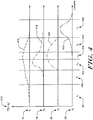
- a probability distribution may be determined based on the reported estimated position of the object and the performance characteristics of the sensor.
- example curve 412 may represent the probability distribution of the estimated position of the object as determined by sensor 12.
- example curve 416 may be the probability distribution of the estimated position of the object as determined by sensor 16.
- Example curve 420 may indicate the probability distribution of the estimated position of the object as determined by sensor 20, and example curve 424 may represent the probability distribution of the estimated position of the object as determined by sensor 24.
- the four probability distributions corresponding to the four sensors are merely illustrative in nature.
- the probability distributions are preferably segmented into sub-ranges or classes c 1 401, c 2 402, c 3 403, etc. This segmentation results in a plurality of uncertainty boundaries for the estimated position of the object, and a probability value is preferably associated with each sub-range. It should be noted that for each sensor, every sub-range such as those illustrated in Figure 4 may be represented by an uncertainty boundary in Figure 3 . Again, for illustration purposes, only three of the six sub-ranges from Figure 4 are shown as uncertainty boundaries in Figure 3 for each of the four illustrated sensors. It is desirable that the intersections of the plurality of segments result in new boundaries that indicate the probable area wherein the object may be located. These new boundaries may then be statistically evaluated to identify the class with the greatest likelihood of containing the object.
- the probability analysis may be further extended to combine the quantitative data and qualitative information (e.g., symbolic, weather conditions, reliability of source, assumptions, performance history, etc.) to provide more accuracy in locating and tracking the object.
- quantitative data and qualitative information e.g., symbolic, weather conditions, reliability of source, assumptions, performance history, etc.
- all imposed assumptions and quantitative and qualitative indicators may be taken into consideration, and a probability measure reflective of the reliability of the sensor to sense the information is preferably assigned.
- a sensor's overall historic performance data may be extrapolated to obtain a trending indication of the sensor's reliability.
- the extrapolation is preferably applied to each of the parameters (e.g., temperature, pressure, moisture level, visibility, etc.) that impact a sensor's reliability.
- An advantage of this approach is that it permits the combining of any and all types and forms of variables and parameters, collectively referred to as drivers, that can impact a sensor's reliability.
- representative examples of drivers includes fixed known values, probable ranges 504 and 510, fuzzy logic based rules on qualitative environmental conditions 508, fuzzy logic based rules on assumptions effecting sensor's operational performance 502, functional expressions 506, etc.
- Known quantities may be specified as fixed values and uncertain parameters are preferably represented by probability distributions such as 504 and 510.
- the probability distribution 504 may be representative of a best curve fit of historic data from the sensor, and the fuzzy rules on conditions 508, for example, may include qualitative information regarding the effect of environmental conditions (e.g., rain) on the accuracy of a reading from a sensor.
- all the defined drivers are preferably input to a neural network with multi-level perceptron 520 for estimating the nonlinear relationship between the driver's values and the sensor's reliability.
- Neural network 520 may be trained to determine the reliability measure, P[s] , and the realization measure P[s k ] 530, preferably indicative of the mean of the sensor reliability measure for a given class.
- a conjunctive fusion method which provides an estimation of the intersections of the probability measures, is preferably applied to all parameters affecting sensor reliability to identify the class with the most likely probability of defining an object's position.
- a method and system of the preferred embodiment of the present invention for locating and tracking an object, such as an airborne aircraft, preferably using statistical analysis and probability theory for fusing (or aggregating) quantitative data and qualitative information from a plurality of sensors and sources.
- an object such as an airborne aircraft
- statistical analysis and probability theory for fusing (or aggregating) quantitative data and qualitative information from a plurality of sensors and sources.
- a plurality of local fusion centers may be considered as a plurality of sensors reporting information on the position and probability distribution for a plurality of objects.
- the plurality of local object locators may transmit the plurality of object locations and probability distributions to a central (or global) fusion center for further locating and tracking of objects on a global basis.
- a site such as an airport
- the plurality of local object locators at a site may be considered as providing location and probability distribution information to a site fusion center for that airport, which in turn may transmit relevant data to yet another fusion center possibly receiving data from other site fusion centers.
- the lowest-most local fusion center may either transmit the fused data including object positions and probability distributions, and/or all the quantitative data and qualitative information received from its associated sensors.
Landscapes
- Engineering & Computer Science (AREA)
- Physics & Mathematics (AREA)
- Radar, Positioning & Navigation (AREA)
- Remote Sensing (AREA)
- General Physics & Mathematics (AREA)
- Aviation & Aerospace Engineering (AREA)
- Electromagnetism (AREA)
- Computer Networks & Wireless Communication (AREA)
- Radar Systems Or Details Thereof (AREA)
Claims (13)
- Système pour déterminer la position la plus probable d'un objet, ledit système comprenant :une pluralité de capteurs fournissant chacun une position estimée de l'objet ; etun processeur de données pour :déterminer une distribution de probabilité de capteur associée pour chaque capteur sur la base de la position estimée de l'objet fournie par le capteur et des caractéristiques de performances du capteur, où les caractéristiques de performances du capteur sont soit accédées par le processeur de données à partir d'une base de données, soit fournies au processeur de données par le capteur, où, en outre, les caractéristiques de performances du capteur comprennent au moins une caractéristique parmi les suivantes : précision, fiabilité, effet des conditions environnementales et dégradation avec l'âge ;segmenter la distribution de probabilité de capteur associée pour chaque capteur en sous-plages, chaque sous-plage étant représentée par un segment de frontière d'incertitude ;pour chaque sous-plage, affecter une mesure de probabilité reflétant la fiabilité de chaque capteur pour détecter la position de l'objet ;utiliser une simulation statistique pour manipuler les mesures de probabilité associées à chaque sous-plage de chaque capteur pour générer une valeur indicative de la position la plus probable de l'objet et une distribution de probabilité associée pour la position la plus probable de l'objet ;appliquer un procédé de fusion conjonctive à la position estimée de l'objet à partir de chacun de la pluralité de capteurs et des distributions de probabilité de capteur associées pour identifier une région d'intersection des sous-plages avec la probabilité la plus probable de définition de la position de l'objet.
- Système selon la revendication 1, comprenant en outre un ensemble de règles de logique floue appliquées à l'une ou aux plusieurs caractéristiques de performances des capteurs.
- Système selon la revendication 1, comprenant en outre un ensemble de règles de logique floue appliquées à un ou plusieurs paramètres qui affectent les une ou plusieurs caractéristiques de performances et/ou la distribution de probabilité de capteur.
- Système selon la revendication 1, comprenant en outre un réseau de neurones appliqué aux une ou plusieurs caractéristiques de performances des capteurs.
- Système selon la revendication 1, comprenant en outre un réseau de neurones appliqué à un ou plusieurs paramètres qui affectent les une ou plusieurs caractéristiques de performances et/ou la distribution de probabilité de capteur.
- Système selon la revendication 1, dans lequel des paramètres affectant des incertitudes de capteur sont manipulés par une règle de probabilité conditionnelle pour déterminer une distribution de probabilité conditionnelle a posteriori pour chaque sous-plage.
- Système selon la revendication 1, dans lequel toutes les distributions de probabilité pour la position de l'objet ont des sous-plages communes.
- Système selon la revendication 1, pour suivre la position relative d'une pluralité d'objets.
- Système selon la revendication 1, dans lequel le capteur comprend une pluralité de systèmes radar.
- Système selon la revendication 1, dans lequel le capteur comprend une pluralité de systèmes de balise.
- Système pour déterminer une position globale d'un objet, ledit système comprenant une pluralité de systèmes locaux tels que décrits dans la revendication 1, avec chaque système local fournissant une valeur indicative de la position la plus probable de l'objet.
- Système selon la revendication 11, dans lequel chaque système local fournit une distribution de probabilité pour la position la plus probable de l'objet.
- Système selon la revendication 1, dans lequel, en outre, le processeur de données :pondère chaque segment de frontière d'incertitude par une mesure de probabilité ; etapplique une approche combinatoire statistique pour identifier la position la plus probable de l'objet avec une région d'incertitude inférieure aux segments de frontière d'incertitude.
Applications Claiming Priority (3)
| Application Number | Priority Date | Filing Date | Title |
|---|---|---|---|
| US14626 | 1993-02-08 | ||
| US10/014,626 US7099796B2 (en) | 2001-10-22 | 2001-10-22 | Multi-sensor information fusion technique |
| PCT/US2002/033160 WO2003083500A2 (fr) | 2001-10-22 | 2002-10-17 | Technique de fusion de donnees de plusieurs detecteurs |
Publications (2)
| Publication Number | Publication Date |
|---|---|
| EP1438603A2 EP1438603A2 (fr) | 2004-07-21 |
| EP1438603B1 true EP1438603B1 (fr) | 2017-03-22 |
Family
ID=21766631
Family Applications (1)
| Application Number | Title | Priority Date | Filing Date |
|---|---|---|---|
| EP02806775.9A Expired - Lifetime EP1438603B1 (fr) | 2001-10-22 | 2002-10-17 | Technique de fusion de donnees de plusieurs detecteurs |
Country Status (5)
| Country | Link |
|---|---|
| US (1) | US7099796B2 (fr) |
| EP (1) | EP1438603B1 (fr) |
| CN (1) | CN100470256C (fr) |
| AU (1) | AU2002367633A1 (fr) |
| WO (1) | WO2003083500A2 (fr) |
Cited By (2)
| Publication number | Priority date | Publication date | Assignee | Title |
|---|---|---|---|---|
| DE102018220941A1 (de) | 2018-12-04 | 2020-06-04 | Robert Bosch Gmbh | Auswertung von Messgrößen mit KI-Modulen unter Berücksichtigung von Messunsicherheiten |
| US20220334200A1 (en) * | 2021-04-20 | 2022-10-20 | Allegro Microsystems, Llc | Multi-domain detector based on artificial neural network |
Families Citing this family (70)
| Publication number | Priority date | Publication date | Assignee | Title |
|---|---|---|---|---|
| US7146260B2 (en) | 2001-04-24 | 2006-12-05 | Medius, Inc. | Method and apparatus for dynamic configuration of multiprocessor system |
| US10298735B2 (en) | 2001-04-24 | 2019-05-21 | Northwater Intellectual Property Fund L.P. 2 | Method and apparatus for dynamic configuration of a multiprocessor health data system |
| US6944566B2 (en) * | 2002-03-26 | 2005-09-13 | Lockheed Martin Corporation | Method and system for multi-sensor data fusion using a modified dempster-shafer theory |
| US7219032B2 (en) | 2002-04-20 | 2007-05-15 | John Louis Spiesberger | Estimation algorithms and location techniques |
| US7298868B2 (en) * | 2002-10-08 | 2007-11-20 | Siemens Corporate Research, Inc. | Density estimation-based information fusion for multiple motion computation |
| SE0300894D0 (sv) * | 2003-03-28 | 2003-03-28 | Saab Ab | Metod att fastställa regler för en anordning som är avsedd att kunna användas för att generera beslutstöd |
| JP3931879B2 (ja) * | 2003-11-28 | 2007-06-20 | 株式会社デンソー | センサフュージョンシステム及びそれを用いた車両制御装置 |
| GB2432231B (en) * | 2004-04-29 | 2008-12-03 | Blaga Nikolova Iordanova | Global networking infrastructure of ground integrated operational decision support systems and their global mechanisms of control of trajectories |
| GB2430278B (en) * | 2004-04-29 | 2008-12-03 | Blaga N Iordanova | Global neural network processes and control mechanisms for automated air space-time allocation and control of 4D trajectories |
| US20060080328A1 (en) * | 2004-10-08 | 2006-04-13 | Anderson James A | Information fusion |
| US7081849B2 (en) | 2004-10-28 | 2006-07-25 | Northrop Grumman Corporation | Process for sensor resources management |
| US7167127B2 (en) | 2004-11-08 | 2007-01-23 | Northrop Grumman Corporation | Process for tracking vehicles |
| US7337650B1 (en) | 2004-11-09 | 2008-03-04 | Medius Inc. | System and method for aligning sensors on a vehicle |
| EP1851565B1 (fr) * | 2005-01-18 | 2009-10-14 | Marinvent Corporation | Procede et appareil de regroupement de capteurs permettant d'obtenir une position d'une cible d'interet |
| US7646336B2 (en) * | 2006-03-24 | 2010-01-12 | Containertrac, Inc. | Automated asset positioning for location and inventory tracking using multiple positioning techniques |
| US7925117B2 (en) * | 2006-06-27 | 2011-04-12 | Honeywell International Inc. | Fusion of sensor data and synthetic data to form an integrated image |
| US8648867B2 (en) | 2006-09-25 | 2014-02-11 | Neurala Llc | Graphic processor based accelerator system and method |
| US8666936B2 (en) | 2006-10-05 | 2014-03-04 | Trimble Navigation Limited | System and method for asset management |
| US9111234B2 (en) * | 2006-10-05 | 2015-08-18 | Trimble Navigation Limited | Enabling notifications pertaining to an asset |
| US9747329B2 (en) | 2006-10-05 | 2017-08-29 | Trimble Inc. | Limiting access to asset management information |
| US9536405B2 (en) | 2006-10-05 | 2017-01-03 | Trimble Inc. | Unreported event status change determination and alerting |
| US9519876B2 (en) * | 2006-10-05 | 2016-12-13 | Trimble Navigation Limited | Method for providing maintenance to an asset |
| US20080086391A1 (en) * | 2006-10-05 | 2008-04-10 | Kurt Maynard | Impromptu asset tracking |
| US8645176B2 (en) * | 2006-10-05 | 2014-02-04 | Trimble Navigation Limited | Utilizing historical data in an asset management environment |
| US9747571B2 (en) | 2006-10-05 | 2017-08-29 | Trimble Inc. | Integrated asset management |
| US9773222B2 (en) * | 2006-10-05 | 2017-09-26 | Trimble Inc. | Externally augmented asset management |
| US9041561B2 (en) * | 2006-10-05 | 2015-05-26 | Trimble Navigation Limited | Method for controlling power usage of a reporting device |
| US9811949B2 (en) | 2006-10-05 | 2017-11-07 | Trimble Inc. | Method for providing status information pertaining to an asset |
| US8965841B2 (en) * | 2006-10-05 | 2015-02-24 | Trimble Navigation Limited | Method for automatic asset classification |
| US7539593B2 (en) * | 2007-04-27 | 2009-05-26 | Invensys Systems, Inc. | Self-validated measurement systems |
| US8600932B2 (en) | 2007-05-07 | 2013-12-03 | Trimble Navigation Limited | Telematic asset microfluidic analysis |
| JP4991876B2 (ja) * | 2007-11-12 | 2012-08-01 | ビ−エイイ− システムズ パブリック リミテッド カンパニ− | センサ制御 |
| US7917332B2 (en) | 2007-11-12 | 2011-03-29 | Bae Systems Plc | Sensor control |
| US9404775B2 (en) * | 2008-04-30 | 2016-08-02 | Honeywell International Inc. | Systems and methods for identifying faulty sensors |
| US10535275B2 (en) | 2008-08-04 | 2020-01-14 | Aviation Communication & Surveillance Systems Llc | Systems and methods for conflict detection using position uncertainty |
| US9358924B1 (en) * | 2009-05-08 | 2016-06-07 | Eagle Harbor Holdings, Llc | System and method for modeling advanced automotive safety systems |
| WO2011137197A1 (fr) * | 2010-04-27 | 2011-11-03 | Aviation Communication & Surveillance Systems Llc | Systèmes et procédés pour détecter un conflit à l'aide de seuils dynamiques |
| CA2803404A1 (fr) | 2010-11-15 | 2012-05-24 | Image Sensing Systems, Inc. | Systeme de detection de la circulation hybride et procede associe |
| US9472097B2 (en) | 2010-11-15 | 2016-10-18 | Image Sensing Systems, Inc. | Roadway sensing systems |
| US8468111B1 (en) | 2010-11-30 | 2013-06-18 | Raytheon Company | Determining confidence of object identification |
| US8260052B1 (en) | 2010-11-30 | 2012-09-04 | Raytheon Company | Object identification via data fusion |
| US8595177B1 (en) | 2011-03-08 | 2013-11-26 | Raytheon Company | Risk management for object identification |
| US9739763B2 (en) | 2011-05-16 | 2017-08-22 | Trimble Inc. | Telematic locomotive microfluidic analysis |
| US9760685B2 (en) | 2011-05-16 | 2017-09-12 | Trimble Inc. | Telematic microfluidic analysis using handheld device |
| JP6075287B2 (ja) * | 2011-06-30 | 2017-02-08 | 日本電気株式会社 | 解析エンジン制御装置 |
| EP2549294B8 (fr) * | 2011-07-20 | 2019-10-02 | Delphi Technologies, Inc. | Procédé pour déceler et confirmer des conditions de conduite critiques |
| CN102707280B (zh) * | 2012-02-27 | 2014-02-05 | 西北工业大学 | 稳定结构的多目标跟踪方法 |
| CN102590810B (zh) * | 2012-02-27 | 2014-04-16 | 西北工业大学 | 三角平方根分解的多目标跟踪方法 |
| WO2014204615A2 (fr) | 2013-05-22 | 2014-12-24 | Neurala, Inc. | Procédés et appareil pour une architecture de temps d'exécution distribuée non spécifique itérative et son application à une intelligence en nuage |
| EP2999940A4 (fr) | 2013-05-22 | 2017-11-15 | Neurala Inc. | Procédés et appareil pour intégration sensorielle précoce et acquisition robuste de connaissances du monde réel |
| FR3013834B1 (fr) * | 2013-11-28 | 2015-12-25 | Airbus Operations Sas | Methode de fusion de donnees de capteurs utilisant un critere de coherence |
| US9626566B2 (en) | 2014-03-19 | 2017-04-18 | Neurala, Inc. | Methods and apparatus for autonomous robotic control |
| KR20170036657A (ko) | 2014-03-19 | 2017-04-03 | 뉴럴라 인코포레이티드 | 자율 로봇 제어를 위한 방법들 및 장치 |
| US9361691B2 (en) * | 2014-08-21 | 2016-06-07 | Honeywell International Inc. | Systems and methods for detecting misalignment between a helipad and an associated structure |
| CN104504728B (zh) * | 2014-09-16 | 2016-05-04 | 深圳大学 | 多机动目标跟踪方法、系统及其广义联合概率数据关联器 |
| US10762440B1 (en) | 2015-09-24 | 2020-09-01 | Apple Inc. | Sensor fusion and deep learning |
| US10304335B2 (en) | 2016-04-12 | 2019-05-28 | Ford Global Technologies, Llc | Detecting available parking spaces |
| US20170314925A1 (en) | 2016-04-28 | 2017-11-02 | Rogerson Aircraft Corporation | System and method for providing terrain imagery during low visibility conditions |
| US10451422B2 (en) | 2016-04-28 | 2019-10-22 | Rogerson Aircraft Corporation | System and method for providing persistent mission data to a fleet of vehicles |
| US10671068B1 (en) | 2016-09-21 | 2020-06-02 | Apple Inc. | Shared sensor data across sensor processing pipelines |
| US10482339B2 (en) | 2016-12-09 | 2019-11-19 | United States Of America As Represented By The Secretary Of The Air Force | Quantifying computer vision algorithm performance in the presence of system uncertainty |
| US10228693B2 (en) | 2017-01-13 | 2019-03-12 | Ford Global Technologies, Llc | Generating simulated sensor data for training and validation of detection models |
| CN107133555B (zh) * | 2017-01-20 | 2020-10-23 | 西南电子技术研究所(中国电子科技集团公司第十研究所) | 识别8字运动轨迹目标的方法 |
| DE102017212429A1 (de) * | 2017-07-20 | 2019-01-24 | Robert Bosch Gmbh | Verfahren zum Kartieren eines Streckenabschnitts und Informationssystem |
| CN107920080A (zh) * | 2017-11-22 | 2018-04-17 | 郑州云海信息技术有限公司 | 一种特征数据采集方法和系统 |
| KR102845010B1 (ko) * | 2019-01-09 | 2025-08-12 | 트리나미엑스 게엠베하 | 적어도 하나의 대상체의 위치를 결정하기 위한 검출기 |
| CN110135561B (zh) * | 2019-04-29 | 2021-06-11 | 北京航天自动控制研究所 | 一种实时在线飞行器ai神经网络系统 |
| US11814084B2 (en) * | 2021-12-17 | 2023-11-14 | Zoox, Inc. | Track confidence model |
| CN115540823B (zh) * | 2022-11-28 | 2023-03-10 | 中国水利水电第七工程局有限公司 | 一种变截面超高墩竖直度测控方法 |
| CN115755133A (zh) * | 2022-12-28 | 2023-03-07 | 广东高标电子科技有限公司 | 一种定位方法、装置、设备和存储介质 |
Family Cites Families (26)
| Publication number | Priority date | Publication date | Assignee | Title |
|---|---|---|---|---|
| DE4026740A1 (de) * | 1990-08-24 | 1992-02-27 | Wild Heerbrugg Ag | Verfahren zur praezisen lagebestimmung |
| CN1063364A (zh) * | 1991-11-16 | 1992-08-05 | 黔南布依族苗族自治州林业科学研究所 | 图示导航系统装置 |
| US5311194A (en) * | 1992-09-15 | 1994-05-10 | Navsys Corporation | GPS precision approach and landing system for aircraft |
| US5661666A (en) * | 1992-11-06 | 1997-08-26 | The United States Of America As Represented By The Secretary Of The Navy | Constant false probability data fusion system |
| JP3232724B2 (ja) * | 1992-12-08 | 2001-11-26 | 株式会社デンソー | 車間距離制御装置 |
| US5548293A (en) * | 1993-03-24 | 1996-08-20 | Leland Stanford Junior University | System and method for generating attitude determinations using GPS |
| US5482314A (en) * | 1994-04-12 | 1996-01-09 | Aerojet General Corporation | Automotive occupant sensor system and method of operation by sensor fusion |
| FR2718875B1 (fr) * | 1994-04-15 | 1996-05-15 | Sextant Avionique | Dispositif d'aide à l'atterrissage. |
| US5483241A (en) * | 1994-05-09 | 1996-01-09 | Rockwell International Corporation | Precision location of aircraft using ranging |
| US5961571A (en) * | 1994-12-27 | 1999-10-05 | Siemens Corporated Research, Inc | Method and apparatus for automatically tracking the location of vehicles |
| FR2735240B1 (fr) * | 1995-06-06 | 1998-01-30 | Soc Et Rech Et Const Electroni | Procede et dispositif pour la determination precise d'un point masque par radiolocalisation satellitaire. |
| US5832187A (en) * | 1995-11-03 | 1998-11-03 | Lemelson Medical, Education & Research Foundation, L.P. | Fire detection systems and methods |
| US5987591A (en) * | 1995-12-27 | 1999-11-16 | Fanuc Limited | Multiple-sensor robot system for obtaining two-dimensional image and three-dimensional position information |
| BR9707716A (pt) | 1996-02-29 | 2000-01-04 | Siemens Ag | Sistema de condução de aeroportos, especialmente sistema de condução de tráfego no solo de tráfego no solo de aeroportos |
| US5940523A (en) * | 1996-03-19 | 1999-08-17 | University Corporation For Atmospheric Research | Method of moment estimation and feature extraction for devices which measure spectra as a function of range or time |
| US5948043A (en) * | 1996-11-08 | 1999-09-07 | Etak, Inc. | Navigation system using GPS data |
| US6324532B1 (en) * | 1997-02-07 | 2001-11-27 | Sarnoff Corporation | Method and apparatus for training a neural network to detect objects in an image |
| US5850625A (en) * | 1997-03-13 | 1998-12-15 | Accurate Automation Corporation | Sensor fusion apparatus and method |
| US6084510A (en) * | 1997-04-18 | 2000-07-04 | Lemelson; Jerome H. | Danger warning and emergency response system and method |
| US6996549B2 (en) * | 1998-05-01 | 2006-02-07 | Health Discovery Corporation | Computer-aided image analysis |
| US6499025B1 (en) * | 1999-06-01 | 2002-12-24 | Microsoft Corporation | System and method for tracking objects by fusing results of multiple sensing modalities |
| US6456239B1 (en) * | 1999-08-25 | 2002-09-24 | Rf Technologies, Inc. | Method and apparatus for locating mobile tags |
| US6745089B2 (en) * | 2000-02-01 | 2004-06-01 | California Institute Of Technology | Adaptable state based control system |
| US6445983B1 (en) * | 2000-07-07 | 2002-09-03 | Case Corporation | Sensor-fusion navigator for automated guidance of off-road vehicles |
| US6542809B2 (en) * | 2001-02-26 | 2003-04-01 | Honeywell International Inc. | Method and system for displaying target vehicle position information |
| US7437125B2 (en) * | 2001-02-27 | 2008-10-14 | The Boeing Company | EIRP statistical calculation method |
-
2001
- 2001-10-22 US US10/014,626 patent/US7099796B2/en not_active Expired - Lifetime
-
2002
- 2002-10-17 EP EP02806775.9A patent/EP1438603B1/fr not_active Expired - Lifetime
- 2002-10-17 WO PCT/US2002/033160 patent/WO2003083500A2/fr not_active Ceased
- 2002-10-17 CN CNB028259424A patent/CN100470256C/zh not_active Expired - Fee Related
- 2002-10-17 AU AU2002367633A patent/AU2002367633A1/en not_active Abandoned
Non-Patent Citations (1)
| Title |
|---|
| None * |
Cited By (3)
| Publication number | Priority date | Publication date | Assignee | Title |
|---|---|---|---|---|
| DE102018220941A1 (de) | 2018-12-04 | 2020-06-04 | Robert Bosch Gmbh | Auswertung von Messgrößen mit KI-Modulen unter Berücksichtigung von Messunsicherheiten |
| US20220334200A1 (en) * | 2021-04-20 | 2022-10-20 | Allegro Microsystems, Llc | Multi-domain detector based on artificial neural network |
| US12360181B2 (en) * | 2021-04-20 | 2025-07-15 | Allegro Microsystems, Llc | Multi-domain detector based on artificial neural network |
Also Published As
| Publication number | Publication date |
|---|---|
| AU2002367633A8 (en) | 2003-10-13 |
| US7099796B2 (en) | 2006-08-29 |
| WO2003083500A3 (fr) | 2003-12-11 |
| EP1438603A2 (fr) | 2004-07-21 |
| AU2002367633A1 (en) | 2003-10-13 |
| US20030078754A1 (en) | 2003-04-24 |
| WO2003083500A2 (fr) | 2003-10-09 |
| CN1688896A (zh) | 2005-10-26 |
| CN100470256C (zh) | 2009-03-18 |
Similar Documents
| Publication | Publication Date | Title |
|---|---|---|
| EP1438603B1 (fr) | Technique de fusion de donnees de plusieurs detecteurs | |
| US11495134B2 (en) | System and method for database augmented ground collision avoidance | |
| US9245451B2 (en) | Air traffic control system | |
| EP1974333B1 (fr) | Contrôle de la circulation aérienne | |
| US11790794B2 (en) | System and method for community provided weather updates for aircraft | |
| US6462697B1 (en) | System and method for classifying and tracking aircraft vehicles on the grounds of an airport | |
| US8200377B2 (en) | System for securing an aircraft flight plan | |
| US7979197B2 (en) | Airport traffic management | |
| EP3048424B1 (fr) | Procédés et systèmes pour affichage d'informations de prévisions météorologiques sur la base d'un itinéraire | |
| EP3594924B1 (fr) | Systèmes et procédés de détection de la turbulence de l'air en fonction de la position de l'aéronef | |
| Wu et al. | Detect and avoid alerting performance with limited surveillance volume for non-cooperative aircraft | |
| US20250083832A1 (en) | Systems and methods for increasing fuel efficiency for an aircraft | |
| Wayllace et al. | DRAGON-V: detection and recognition of airplane goals with navigational visualization | |
| US20260042459A1 (en) | Object classification system from unstructured point clouds | |
| US20250292694A1 (en) | Systems and methods for aircraft ground collision avoidance | |
| Rong et al. | Intelligent system design with fixed-base simulation validation for general aviation | |
| SCARDINA | RESOLUTION SERVICE | |
| HK1122124B (en) | Air traffic control | |
| HK1122125B (en) | Air traffic control | |
| HK1163324B (en) | Air traffic control |
Legal Events
| Date | Code | Title | Description |
|---|---|---|---|
| PUAI | Public reference made under article 153(3) epc to a published international application that has entered the european phase |
Free format text: ORIGINAL CODE: 0009012 |
|
| 17P | Request for examination filed |
Effective date: 20040507 |
|
| AK | Designated contracting states |
Kind code of ref document: A2 Designated state(s): AT BE BG CH CY CZ DE DK EE ES FI FR GB GR IE IT LI LU MC NL PT SE SK TR |
|
| AX | Request for extension of the european patent |
Extension state: AL LT LV MK RO SI |
|
| 17Q | First examination report despatched |
Effective date: 20100406 |
|
| RAP1 | Party data changed (applicant data changed or rights of an application transferred) |
Owner name: HONEYWELL INTERNATIONAL INC. |
|
| REG | Reference to a national code |
Ref country code: DE Ref legal event code: R079 Ref document number: 60248760 Country of ref document: DE Free format text: PREVIOUS MAIN CLASS: G01S0001000000 Ipc: G01S0013910000 |
|
| GRAP | Despatch of communication of intention to grant a patent |
Free format text: ORIGINAL CODE: EPIDOSNIGR1 |
|
| RIC1 | Information provided on ipc code assigned before grant |
Ipc: G01S 13/91 20060101AFI20161017BHEP Ipc: G08G 5/00 20060101ALI20161017BHEP Ipc: G01S 17/87 20060101ALI20161017BHEP Ipc: G01S 13/72 20060101ALN20161017BHEP |
|
| INTG | Intention to grant announced |
Effective date: 20161111 |
|
| GRAS | Grant fee paid |
Free format text: ORIGINAL CODE: EPIDOSNIGR3 |
|
| GRAA | (expected) grant |
Free format text: ORIGINAL CODE: 0009210 |
|
| AK | Designated contracting states |
Kind code of ref document: B1 Designated state(s): AT BE BG CH CY CZ DE DK EE ES FI FR GB GR IE IT LI LU MC NL PT SE SK TR |
|
| REG | Reference to a national code |
Ref country code: GB Ref legal event code: FG4D |
|
| REG | Reference to a national code |
Ref country code: CH Ref legal event code: EP |
|
| REG | Reference to a national code |
Ref country code: AT Ref legal event code: REF Ref document number: 878329 Country of ref document: AT Kind code of ref document: T Effective date: 20170415 |
|
| REG | Reference to a national code |
Ref country code: IE Ref legal event code: FG4D |
|
| REG | Reference to a national code |
Ref country code: DE Ref legal event code: R096 Ref document number: 60248760 Country of ref document: DE |
|
| REG | Reference to a national code |
Ref country code: NL Ref legal event code: MP Effective date: 20170322 |
|
| PG25 | Lapsed in a contracting state [announced via postgrant information from national office to epo] |
Ref country code: FI Free format text: LAPSE BECAUSE OF FAILURE TO SUBMIT A TRANSLATION OF THE DESCRIPTION OR TO PAY THE FEE WITHIN THE PRESCRIBED TIME-LIMIT Effective date: 20170322 Ref country code: GR Free format text: LAPSE BECAUSE OF FAILURE TO SUBMIT A TRANSLATION OF THE DESCRIPTION OR TO PAY THE FEE WITHIN THE PRESCRIBED TIME-LIMIT Effective date: 20170623 |
|
| REG | Reference to a national code |
Ref country code: AT Ref legal event code: MK05 Ref document number: 878329 Country of ref document: AT Kind code of ref document: T Effective date: 20170322 |
|
| PG25 | Lapsed in a contracting state [announced via postgrant information from national office to epo] |
Ref country code: BG Free format text: LAPSE BECAUSE OF FAILURE TO SUBMIT A TRANSLATION OF THE DESCRIPTION OR TO PAY THE FEE WITHIN THE PRESCRIBED TIME-LIMIT Effective date: 20170622 Ref country code: SE Free format text: LAPSE BECAUSE OF FAILURE TO SUBMIT A TRANSLATION OF THE DESCRIPTION OR TO PAY THE FEE WITHIN THE PRESCRIBED TIME-LIMIT Effective date: 20170322 |
|
| PG25 | Lapsed in a contracting state [announced via postgrant information from national office to epo] |
Ref country code: NL Free format text: LAPSE BECAUSE OF FAILURE TO SUBMIT A TRANSLATION OF THE DESCRIPTION OR TO PAY THE FEE WITHIN THE PRESCRIBED TIME-LIMIT Effective date: 20170322 |
|
| PG25 | Lapsed in a contracting state [announced via postgrant information from national office to epo] |
Ref country code: EE Free format text: LAPSE BECAUSE OF FAILURE TO SUBMIT A TRANSLATION OF THE DESCRIPTION OR TO PAY THE FEE WITHIN THE PRESCRIBED TIME-LIMIT Effective date: 20170322 Ref country code: AT Free format text: LAPSE BECAUSE OF FAILURE TO SUBMIT A TRANSLATION OF THE DESCRIPTION OR TO PAY THE FEE WITHIN THE PRESCRIBED TIME-LIMIT Effective date: 20170322 Ref country code: IT Free format text: LAPSE BECAUSE OF FAILURE TO SUBMIT A TRANSLATION OF THE DESCRIPTION OR TO PAY THE FEE WITHIN THE PRESCRIBED TIME-LIMIT Effective date: 20170322 Ref country code: CZ Free format text: LAPSE BECAUSE OF FAILURE TO SUBMIT A TRANSLATION OF THE DESCRIPTION OR TO PAY THE FEE WITHIN THE PRESCRIBED TIME-LIMIT Effective date: 20170322 Ref country code: SK Free format text: LAPSE BECAUSE OF FAILURE TO SUBMIT A TRANSLATION OF THE DESCRIPTION OR TO PAY THE FEE WITHIN THE PRESCRIBED TIME-LIMIT Effective date: 20170322 Ref country code: ES Free format text: LAPSE BECAUSE OF FAILURE TO SUBMIT A TRANSLATION OF THE DESCRIPTION OR TO PAY THE FEE WITHIN THE PRESCRIBED TIME-LIMIT Effective date: 20170322 |
|
| REG | Reference to a national code |
Ref country code: FR Ref legal event code: PLFP Year of fee payment: 16 |
|
| PG25 | Lapsed in a contracting state [announced via postgrant information from national office to epo] |
Ref country code: PT Free format text: LAPSE BECAUSE OF FAILURE TO SUBMIT A TRANSLATION OF THE DESCRIPTION OR TO PAY THE FEE WITHIN THE PRESCRIBED TIME-LIMIT Effective date: 20170724 |
|
| REG | Reference to a national code |
Ref country code: DE Ref legal event code: R097 Ref document number: 60248760 Country of ref document: DE |
|
| PLBE | No opposition filed within time limit |
Free format text: ORIGINAL CODE: 0009261 |
|
| STAA | Information on the status of an ep patent application or granted ep patent |
Free format text: STATUS: NO OPPOSITION FILED WITHIN TIME LIMIT |
|
| PG25 | Lapsed in a contracting state [announced via postgrant information from national office to epo] |
Ref country code: DK Free format text: LAPSE BECAUSE OF FAILURE TO SUBMIT A TRANSLATION OF THE DESCRIPTION OR TO PAY THE FEE WITHIN THE PRESCRIBED TIME-LIMIT Effective date: 20170322 |
|
| 26N | No opposition filed |
Effective date: 20180102 |
|
| PG25 | Lapsed in a contracting state [announced via postgrant information from national office to epo] |
Ref country code: MC Free format text: LAPSE BECAUSE OF FAILURE TO SUBMIT A TRANSLATION OF THE DESCRIPTION OR TO PAY THE FEE WITHIN THE PRESCRIBED TIME-LIMIT Effective date: 20170322 |
|
| REG | Reference to a national code |
Ref country code: CH Ref legal event code: PL |
|
| REG | Reference to a national code |
Ref country code: IE Ref legal event code: MM4A |
|
| PG25 | Lapsed in a contracting state [announced via postgrant information from national office to epo] |
Ref country code: LU Free format text: LAPSE BECAUSE OF NON-PAYMENT OF DUE FEES Effective date: 20171017 Ref country code: LI Free format text: LAPSE BECAUSE OF NON-PAYMENT OF DUE FEES Effective date: 20171031 Ref country code: CH Free format text: LAPSE BECAUSE OF NON-PAYMENT OF DUE FEES Effective date: 20171031 |
|
| REG | Reference to a national code |
Ref country code: BE Ref legal event code: MM Effective date: 20171031 |
|
| PG25 | Lapsed in a contracting state [announced via postgrant information from national office to epo] |
Ref country code: BE Free format text: LAPSE BECAUSE OF NON-PAYMENT OF DUE FEES Effective date: 20171031 |
|
| REG | Reference to a national code |
Ref country code: FR Ref legal event code: PLFP Year of fee payment: 17 |
|
| PG25 | Lapsed in a contracting state [announced via postgrant information from national office to epo] |
Ref country code: IE Free format text: LAPSE BECAUSE OF NON-PAYMENT OF DUE FEES Effective date: 20171017 |
|
| PG25 | Lapsed in a contracting state [announced via postgrant information from national office to epo] |
Ref country code: CY Free format text: LAPSE BECAUSE OF NON-PAYMENT OF DUE FEES Effective date: 20170322 |
|
| PGFP | Annual fee paid to national office [announced via postgrant information from national office to epo] |
Ref country code: DE Payment date: 20191031 Year of fee payment: 18 |
|
| PGFP | Annual fee paid to national office [announced via postgrant information from national office to epo] |
Ref country code: FR Payment date: 20191024 Year of fee payment: 18 |
|
| PG25 | Lapsed in a contracting state [announced via postgrant information from national office to epo] |
Ref country code: TR Free format text: LAPSE BECAUSE OF FAILURE TO SUBMIT A TRANSLATION OF THE DESCRIPTION OR TO PAY THE FEE WITHIN THE PRESCRIBED TIME-LIMIT Effective date: 20170322 |
|
| PGFP | Annual fee paid to national office [announced via postgrant information from national office to epo] |
Ref country code: GB Payment date: 20191029 Year of fee payment: 18 |
|
| REG | Reference to a national code |
Ref country code: DE Ref legal event code: R119 Ref document number: 60248760 Country of ref document: DE |
|
| GBPC | Gb: european patent ceased through non-payment of renewal fee |
Effective date: 20201017 |
|
| PG25 | Lapsed in a contracting state [announced via postgrant information from national office to epo] |
Ref country code: FR Free format text: LAPSE BECAUSE OF NON-PAYMENT OF DUE FEES Effective date: 20201031 Ref country code: DE Free format text: LAPSE BECAUSE OF NON-PAYMENT OF DUE FEES Effective date: 20210501 |
|
| PG25 | Lapsed in a contracting state [announced via postgrant information from national office to epo] |
Ref country code: GB Free format text: LAPSE BECAUSE OF NON-PAYMENT OF DUE FEES Effective date: 20201017 |