EP1439007A2 - Einrichtung zum Aufbringen von Farbe - Google Patents
Einrichtung zum Aufbringen von Farbe Download PDFInfo
- Publication number
- EP1439007A2 EP1439007A2 EP04000978A EP04000978A EP1439007A2 EP 1439007 A2 EP1439007 A2 EP 1439007A2 EP 04000978 A EP04000978 A EP 04000978A EP 04000978 A EP04000978 A EP 04000978A EP 1439007 A2 EP1439007 A2 EP 1439007A2
- Authority
- EP
- European Patent Office
- Prior art keywords
- doctor
- fastening element
- squeegee
- flexible connection
- web
- Prior art date
- Legal status (The legal status is an assumption and is not a legal conclusion. Google has not performed a legal analysis and makes no representation as to the accuracy of the status listed.)
- Granted
Links
Images

Classifications
-
- B—PERFORMING OPERATIONS; TRANSPORTING
- B41—PRINTING; LINING MACHINES; TYPEWRITERS; STAMPS
- B41F—PRINTING MACHINES OR PRESSES
- B41F15/00—Screen printers
- B41F15/14—Details
- B41F15/40—Inking units
- B41F15/42—Inking units comprising squeegees or doctors
-
- B—PERFORMING OPERATIONS; TRANSPORTING
- B05—SPRAYING OR ATOMISING IN GENERAL; APPLYING FLUENT MATERIALS TO SURFACES, IN GENERAL
- B05C—APPARATUS FOR APPLYING FLUENT MATERIALS TO SURFACES, IN GENERAL
- B05C1/00—Apparatus in which liquid or other fluent material is applied to the surface of the work by contact with a member carrying the liquid or other fluent material, e.g. a porous member loaded with a liquid to be applied as a coating
- B05C1/04—Apparatus in which liquid or other fluent material is applied to the surface of the work by contact with a member carrying the liquid or other fluent material, e.g. a porous member loaded with a liquid to be applied as a coating for applying liquid or other fluent material to work of indefinite length
- B05C1/08—Apparatus in which liquid or other fluent material is applied to the surface of the work by contact with a member carrying the liquid or other fluent material, e.g. a porous member loaded with a liquid to be applied as a coating for applying liquid or other fluent material to work of indefinite length using a roller or other rotating member which contacts the work along a generating line
- B05C1/10—Apparatus in which liquid or other fluent material is applied to the surface of the work by contact with a member carrying the liquid or other fluent material, e.g. a porous member loaded with a liquid to be applied as a coating for applying liquid or other fluent material to work of indefinite length using a roller or other rotating member which contacts the work along a generating line the liquid or other fluent material being supplied from inside the roller
-
- B—PERFORMING OPERATIONS; TRANSPORTING
- B05—SPRAYING OR ATOMISING IN GENERAL; APPLYING FLUENT MATERIALS TO SURFACES, IN GENERAL
- B05C—APPARATUS FOR APPLYING FLUENT MATERIALS TO SURFACES, IN GENERAL
- B05C11/00—Component parts, details or accessories not specifically provided for in groups B05C1/00 - B05C9/00
- B05C11/02—Apparatus for spreading or distributing liquids or other fluent materials already applied to a surface ; Controlling means therefor; Control of the thickness of a coating by spreading or distributing liquids or other fluent materials already applied to the coated surface
- B05C11/023—Apparatus for spreading or distributing liquids or other fluent materials already applied to a surface
- B05C11/025—Apparatus for spreading or distributing liquids or other fluent materials already applied to a surface with an essentially cylindrical body, e.g. roll or rod
Definitions
- the object of the present invention is to provide a generic device of this type improve that the squeegee roller of the squeegee device always optimally to the stencil can be pressed.
- an at least partially flexible Connection which a movement of the doctor device relative to the fastener in allows at least two, preferably three, spatial directions between the Doctor device and the fastener is arranged.
- the doctor device can thus according to the invention relative to the fastener move at least two, preferably three spatial directions. It is therefore an adjustment the distance between the fastening element and the doctor device, as well as an oblique and / or Diagonal positions or lateral displacement of the doctor device relative to the Fastening element possible. This ensures that the squeegee roll is always optimal the stencil can be pressed on, as in the sense of optimal print quality is desirable.
- a particularly preferred embodiment variant provides that the at least partially flexible connection between the doctor device and the fastening element at least partially elastic or rubber-elastic material, preferably a cuff elastic or rubber-elastic material. This is the one you want Mobility of the doctor device relative to the fastener guaranteed.
- the at least partially flexible connection between the doctor device and the Fastening element has at least one spring, preferably a helical spring.
- the Fastening element has a clamp device with which the fastening element is detachably attachable to the paint tube. This will above all be quick and with little Effort associated replacement of the doctor device, z. B. to adjust the Squeegee width to the desired printing width.
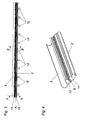
- Fig. 3 shows a side view of an embodiment of the invention Squeegee device with a fastening element 1, on which a flexible connection 8 Doctor device (with a tunnel body 16 as a roller guide and with arranged therein Doctor roll 2) is arranged.
- Fig. 1 shows a section along the line AA, Fig. 2 along the line BB.
- the fastening element 1 consists of a Fastening base body 13 and a clamp device 6 arranged thereon, which consists of an adjustable mounting plate with which the fastening element 1 the color tube 7 of the device can be detachably or removably attached.
- the clamp device 6 is fastened to the fastening base body 13 by means of the Screws 15.
- the flexible connection 8 is arranged according to the invention.
- This has in the embodiment shown one of elastic or rubber-elastic Material formed cuff 9.
- Cuff 9 also several springs 10 may be provided.
- a recess 20 is provided on the lower connecting component 11, into which the nose 19 of the tunnel body 16 can be inserted.
- the firm hold between the bottom Connecting component 11 and the tunnel body 16 is formed on the one hand by the nose 19 and on the other hand via permanent magnets 18 in connection with positioning pins 17. These secure the tunnel body 16 against displacement and thus keep it in the working position.
- in the Tunnel body 16 is a tunnel 3 with a slot-like opening along its longitudinal extent provided in which the doctor roller 2 is guided. Basically, the most varied Doctor rolls, in particular with different diameters, can be used.
- a A favorable variant is in the form of a so-called flow doctor blade in WO 02/07900 A1 portrayed.
- the tunnel body 16 with the tunnel 3 is designed as an interchangeable part around the squeegee various doctor rolls 2 or application rolls with the desired diameter to be able to assign.
- the construction of the junction between the lower Connecting component 11 and the tunnel body 16 is designed so that the power flow that the Ink sump during printing against the doctor roller 2 or doctor device, is intercepted.
- the components 11 and 16 are fixed to one another as above explained about the nose 19 and the pins 17 and the permanent magnets 18. By manual pressure against the working direction release the holding magnets 18 and give the Tunnel body 16 for cleaning or changing to a doctor roll 2 with another Diameter free.
- the doctor blade roller 2 has magnetizable material and is guided in tunnel 3 of a tunnel body 16 made of plastic.
- a series of Magnet 12 magnet 12 (magnetic line) provided.
- FIG. 4 shows a perspective view of the doctor device shown in FIGS. 1 to 3.
- the at least partially flexible connection 8 is a Stiffness that the doctor device, if no further forces on it act, essentially parallel to the fastener 1 holds.
Landscapes
- Engineering & Computer Science (AREA)
- Mechanical Engineering (AREA)
- Coating Apparatus (AREA)
- Electrical Discharge Machining, Electrochemical Machining, And Combined Machining (AREA)
- Circuit Arrangements For Discharge Lamps (AREA)
- Non-Silver Salt Photosensitive Materials And Non-Silver Salt Photography (AREA)
- Treatment Of Fiber Materials (AREA)
- Photographic Developing Apparatuses (AREA)
- Application Of Or Painting With Fluid Materials (AREA)
Abstract
Description
- Fig. 1 und 2
- Schnittdarstellungen zu den erfindungswesentlichen Details eines Ausführungsbeispiels einer erfindungsgemäßen Einrichtung
- Fig. 3
- eine Seitenansicht auf das Ausführungsbeispiel und
- Fig. 4
- eine perspektivische Darstellung des Ausführungsbeispieles
Claims (7)
- Einrichtung zum Aufbringen von Farbe auf eine Warenbahn mit einer Schablone und einer Rakeleinrichtung zum Durchpressen der Farbe durch die Schablone auf die Warenbahn sowie einem Befestigungselement, an dem die Rakeleinrichtung, welche eine Rakelrolle und eine Rollenführung aufweist, gehalten ist, dadurch gekennzeichnet, dass eine zumindest teilweise flexible Verbindung (8), welche eine Bewegung der Rakeleinrichtung relativ zum Befestigungselement (1) in mindestens zwei, vorzugsweise drei, Raumrichtungen zulässt, zwischen der Rakeleinrichtung und dem Befestigungselement (1) angeordnet ist.
- Einrichtung nach Anspruch 1, dadurch gekennzeichnet, dass die zumindest teilweise flexible Verbindung (8) zwischen der Rakeleinrichtung und dem Befestigungselement (1) zumindest teilweise elastisches oder gummielastisches Material, vorzugsweise eine Manschette (9) aus elastischem oder gummielastischem Material, aufweist.
- Einrichtung nach einem der Ansprüche 1 oder 2, dadurch gekennzeichnet, dass die zumindest teilweise flexible Verbindung (8) zwischen der Rakeleinrichtung und dem Befestigungselement (1) mindestens eine Feder (10), vorzugsweise Schraubenfeder, aufweist.
- Einrichtung nach einem der Ansprüche 1 bis 3, dadurch gekennzeichnet, dass die Rollenführung (16) einen in seiner Längsrichtung schlitzartig offenen Tunnel (3) aufweist.
- Einrichtung nach einem der Ansprüche 1 bis 4, dadurch gekennzeichnet, dass die zumindest teilweise flexible Verbindung (8) eine Steifigkeit aufweist, welche die Rakeleinrichtung, wenn keine weiteren Kräfte auf sie einwirken, im Wesentlichen parallel zum Befestigungselement (1) hält.
- Einrichtung zum Aufbringen von Farbe auf eine Warenbahn mit einer Schablone und einer Rakeleinrichtung zum Durchpressen der Farbe durch die Schablone auf die Warenbahn sowie einem Befestigungselement, an dem die Rakeleinrichtung, welche eine Rakelrolle und eine Rollenführung aufweist, gehalten ist, insbesondere nach einem der Ansprüche 1 bis 5, dadurch gekennzeichnet, dass das Befestigungselement (1) eine Klammereinrichtung (6) aufweist, mit der das Befestigungselement (1) lösbar auf das Farbrohr (7) aufsteckbar ist.
- Einrichtung nach einem der Ansprüche 1 bis 6, dadurch gekennzeichnet, dass der Tunnelkörper (16) mit dem Tunnel (3) als Wechselteil ausgebildet ist.
Applications Claiming Priority (2)
| Application Number | Priority Date | Filing Date | Title |
|---|---|---|---|
| AT632003 | 2003-01-20 | ||
| AT0006303A AT412452B (de) | 2003-01-20 | 2003-01-20 | Einrichtung zum aufbringen von farbe |
Publications (3)
| Publication Number | Publication Date |
|---|---|
| EP1439007A2 true EP1439007A2 (de) | 2004-07-21 |
| EP1439007A3 EP1439007A3 (de) | 2007-04-18 |
| EP1439007B1 EP1439007B1 (de) | 2008-03-26 |
Family
ID=32512928
Family Applications (1)
| Application Number | Title | Priority Date | Filing Date |
|---|---|---|---|
| EP04000978A Expired - Lifetime EP1439007B1 (de) | 2003-01-20 | 2004-01-19 | Einrichtung zum Aufbringen von Farbe |
Country Status (3)
| Country | Link |
|---|---|
| EP (1) | EP1439007B1 (de) |
| AT (2) | AT412452B (de) |
| DE (1) | DE502004006631D1 (de) |
Families Citing this family (1)
| Publication number | Priority date | Publication date | Assignee | Title |
|---|---|---|---|---|
| DE102010034137A1 (de) * | 2010-08-12 | 2012-02-16 | Paul Gmbh & Co. Kg Metallgewebe- Und Filterfabriken | Abstreifbeschichtungssystem und -verfahren für leicht- bis hochviskose Flüssigkeiten |
Family Cites Families (3)
| Publication number | Priority date | Publication date | Assignee | Title |
|---|---|---|---|---|
| EP0311728B1 (de) * | 1987-10-10 | 1993-03-10 | Johannes Zimmer | Rakeleinrichtung |
| DE59106731D1 (de) * | 1991-03-21 | 1995-11-23 | Johannes Zimmer | Rakelgerät. |
| DE9112032U1 (de) * | 1991-09-23 | 1993-01-28 | Zimmer, Johannes, Klagenfurt, Kärnten | Rakelgerät |
-
2003
- 2003-01-20 AT AT0006303A patent/AT412452B/de not_active IP Right Cessation
-
2004
- 2004-01-19 DE DE502004006631T patent/DE502004006631D1/de not_active Expired - Fee Related
- 2004-01-19 AT AT04000978T patent/ATE390213T1/de not_active IP Right Cessation
- 2004-01-19 EP EP04000978A patent/EP1439007B1/de not_active Expired - Lifetime
Also Published As
| Publication number | Publication date |
|---|---|
| ATE390213T1 (de) | 2008-04-15 |
| EP1439007A3 (de) | 2007-04-18 |
| DE502004006631D1 (de) | 2008-05-08 |
| AT412452B (de) | 2005-03-25 |
| EP1439007B1 (de) | 2008-03-26 |
| ATA632003A (de) | 2004-08-15 |
Similar Documents
| Publication | Publication Date | Title |
|---|---|---|
| DE2607580B2 (de) | Vorrichtung zum Justieren der Lage der Druckelemente eines Druckkopfes senkrecht zum Druckwiderlager durch ein am Druckkopf angeordnetes Abstandsorgan | |
| DE10317470B4 (de) | Sprühfeuchtwerk | |
| DE2207935A1 (de) | Einstellbare Halterung für eine Abstreichklinge im Inneren einer drehbaren Schablone einer Druckmaschine für Streifenmaterial | |
| DE4213662A1 (de) | Verfahren zum Anstellen einer Kammerrakel an eine farbabgebende Walze und Vorrichtung zur Durchführung des Verfahrens | |
| DE20012945U1 (de) | Haltevorrichtung für mindestens einen Druckkopf eines Tintenstrahldruckers | |
| DE1760393A1 (de) | Rakelvorrichtung | |
| AT412452B (de) | Einrichtung zum aufbringen von farbe | |
| DE1966853A1 (de) | Rakelvorrichtung fuer rotationssiebdruckmaschinen | |
| DE20019548U1 (de) | Variable Kreisbogenschablone | |
| DE1775034B1 (de) | Loesbare nutfederverbindung zur halterung streifen und platten foermiger bauteile insbesondere fuer abstreichleisten an papiermaschinen | |
| DE60221072T2 (de) | Farbvorrichtung und Seitenwand dafür | |
| DE202009005279U1 (de) | Bohr- bzw. Anreißlehre | |
| DE202013100111U1 (de) | Zwinge mit einer Positionierfunktion | |
| DE3021823C2 (de) | Lagerteil mit einer Aufnahmebohrung für eine Stange oder Welle | |
| DE102004059431B4 (de) | Aufhängevorrichtung für Werkzeuge | |
| DE4209566A1 (de) | Rakelgeraet | |
| DE69400654T2 (de) | Vorrichtung zum Aufhängen einer Rakel in einer Zylinderschablone einer Rotationssiebdruckmaschine | |
| EP1882554B1 (de) | Vorrichtung zum Verstellen von Positionierungsstiften zur Lagerfixierung von Werkstücken auf Werkstückträgern | |
| EP0395971B1 (de) | Federbügelzirkel | |
| DE102004042342A1 (de) | Druckplattenanbringungsvorrichtung | |
| DE10341229A1 (de) | Leitwalze | |
| DE202009014160U1 (de) | Schlitzdüsenvorrichtung | |
| DE2017534C (de) | Brillengestell | |
| DE2450231A1 (de) | Rakelanordnung | |
| DE19710871C2 (de) | Vorrichtung zum Auftragen von Flüssigkeiten |
Legal Events
| Date | Code | Title | Description |
|---|---|---|---|
| PUAI | Public reference made under article 153(3) epc to a published international application that has entered the european phase |
Free format text: ORIGINAL CODE: 0009012 |
|
| AK | Designated contracting states |
Kind code of ref document: A2 Designated state(s): AT BE BG CH CY CZ DE DK EE ES FI FR GB GR HU IE IT LI LU MC NL PT RO SE SI SK TR |
|
| AX | Request for extension of the european patent |
Extension state: AL LT LV MK |
|
| PUAL | Search report despatched |
Free format text: ORIGINAL CODE: 0009013 |
|
| AK | Designated contracting states |
Kind code of ref document: A3 Designated state(s): AT BE BG CH CY CZ DE DK EE ES FI FR GB GR HU IE IT LI LU MC NL PT RO SE SI SK TR |
|
| AX | Request for extension of the european patent |
Extension state: AL LT LV MK |
|
| 17P | Request for examination filed |
Effective date: 20070605 |
|
| GRAP | Despatch of communication of intention to grant a patent |
Free format text: ORIGINAL CODE: EPIDOSNIGR1 |
|
| AKX | Designation fees paid |
Designated state(s): AT BE BG CH CY CZ DE DK EE ES FI FR GB GR HU IE IT LI LU MC NL PT RO SE SI SK TR |
|
| GRAS | Grant fee paid |
Free format text: ORIGINAL CODE: EPIDOSNIGR3 |
|
| GRAA | (expected) grant |
Free format text: ORIGINAL CODE: 0009210 |
|
| AK | Designated contracting states |
Kind code of ref document: B1 Designated state(s): AT BE BG CH CY CZ DE DK EE ES FI FR GB GR HU IE IT LI LU MC NL PT RO SE SI SK TR |
|
| REG | Reference to a national code |
Ref country code: GB Ref legal event code: FG4D Free format text: NOT ENGLISH |
|
| REG | Reference to a national code |
Ref country code: IE Ref legal event code: FG4D Free format text: LANGUAGE OF EP DOCUMENT: GERMAN Ref country code: CH Ref legal event code: EP |
|
| REF | Corresponds to: |
Ref document number: 502004006631 Country of ref document: DE Date of ref document: 20080508 Kind code of ref document: P |
|
| PG25 | Lapsed in a contracting state [announced via postgrant information from national office to epo] |
Ref country code: FI Free format text: LAPSE BECAUSE OF FAILURE TO SUBMIT A TRANSLATION OF THE DESCRIPTION OR TO PAY THE FEE WITHIN THE PRESCRIBED TIME-LIMIT Effective date: 20080326 |
|
| NLV1 | Nl: lapsed or annulled due to failure to fulfill the requirements of art. 29p and 29m of the patents act | ||
| PG25 | Lapsed in a contracting state [announced via postgrant information from national office to epo] |
Ref country code: SI Free format text: LAPSE BECAUSE OF FAILURE TO SUBMIT A TRANSLATION OF THE DESCRIPTION OR TO PAY THE FEE WITHIN THE PRESCRIBED TIME-LIMIT Effective date: 20080326 |
|
| REG | Reference to a national code |
Ref country code: IE Ref legal event code: FD4D |
|
| PG25 | Lapsed in a contracting state [announced via postgrant information from national office to epo] |
Ref country code: SK Free format text: LAPSE BECAUSE OF FAILURE TO SUBMIT A TRANSLATION OF THE DESCRIPTION OR TO PAY THE FEE WITHIN THE PRESCRIBED TIME-LIMIT Effective date: 20080326 Ref country code: ES Free format text: LAPSE BECAUSE OF FAILURE TO SUBMIT A TRANSLATION OF THE DESCRIPTION OR TO PAY THE FEE WITHIN THE PRESCRIBED TIME-LIMIT Effective date: 20080707 Ref country code: PT Free format text: LAPSE BECAUSE OF FAILURE TO SUBMIT A TRANSLATION OF THE DESCRIPTION OR TO PAY THE FEE WITHIN THE PRESCRIBED TIME-LIMIT Effective date: 20080901 Ref country code: SE Free format text: LAPSE BECAUSE OF FAILURE TO SUBMIT A TRANSLATION OF THE DESCRIPTION OR TO PAY THE FEE WITHIN THE PRESCRIBED TIME-LIMIT Effective date: 20080626 |
|
| PG25 | Lapsed in a contracting state [announced via postgrant information from national office to epo] |
Ref country code: RO Free format text: LAPSE BECAUSE OF FAILURE TO SUBMIT A TRANSLATION OF THE DESCRIPTION OR TO PAY THE FEE WITHIN THE PRESCRIBED TIME-LIMIT Effective date: 20080326 Ref country code: NL Free format text: LAPSE BECAUSE OF FAILURE TO SUBMIT A TRANSLATION OF THE DESCRIPTION OR TO PAY THE FEE WITHIN THE PRESCRIBED TIME-LIMIT Effective date: 20080326 |
|
| EN | Fr: translation not filed | ||
| PG25 | Lapsed in a contracting state [announced via postgrant information from national office to epo] |
Ref country code: IE Free format text: LAPSE BECAUSE OF FAILURE TO SUBMIT A TRANSLATION OF THE DESCRIPTION OR TO PAY THE FEE WITHIN THE PRESCRIBED TIME-LIMIT Effective date: 20080326 Ref country code: CZ Free format text: LAPSE BECAUSE OF FAILURE TO SUBMIT A TRANSLATION OF THE DESCRIPTION OR TO PAY THE FEE WITHIN THE PRESCRIBED TIME-LIMIT Effective date: 20080326 Ref country code: DK Free format text: LAPSE BECAUSE OF FAILURE TO SUBMIT A TRANSLATION OF THE DESCRIPTION OR TO PAY THE FEE WITHIN THE PRESCRIBED TIME-LIMIT Effective date: 20080326 |
|
| PLBE | No opposition filed within time limit |
Free format text: ORIGINAL CODE: 0009261 |
|
| STAA | Information on the status of an ep patent application or granted ep patent |
Free format text: STATUS: NO OPPOSITION FILED WITHIN TIME LIMIT |
|
| 26N | No opposition filed |
Effective date: 20081230 |
|
| PG25 | Lapsed in a contracting state [announced via postgrant information from national office to epo] |
Ref country code: BG Free format text: LAPSE BECAUSE OF FAILURE TO SUBMIT A TRANSLATION OF THE DESCRIPTION OR TO PAY THE FEE WITHIN THE PRESCRIBED TIME-LIMIT Effective date: 20080626 Ref country code: FR Free format text: LAPSE BECAUSE OF FAILURE TO SUBMIT A TRANSLATION OF THE DESCRIPTION OR TO PAY THE FEE WITHIN THE PRESCRIBED TIME-LIMIT Effective date: 20090116 Ref country code: EE Free format text: LAPSE BECAUSE OF FAILURE TO SUBMIT A TRANSLATION OF THE DESCRIPTION OR TO PAY THE FEE WITHIN THE PRESCRIBED TIME-LIMIT Effective date: 20080326 |
|
| PG25 | Lapsed in a contracting state [announced via postgrant information from national office to epo] |
Ref country code: IT Free format text: LAPSE BECAUSE OF FAILURE TO SUBMIT A TRANSLATION OF THE DESCRIPTION OR TO PAY THE FEE WITHIN THE PRESCRIBED TIME-LIMIT Effective date: 20080326 Ref country code: MC Free format text: LAPSE BECAUSE OF NON-PAYMENT OF DUE FEES Effective date: 20090131 |
|
| REG | Reference to a national code |
Ref country code: CH Ref legal event code: PL |
|
| GBPC | Gb: european patent ceased through non-payment of renewal fee |
Effective date: 20090119 |
|
| PG25 | Lapsed in a contracting state [announced via postgrant information from national office to epo] |
Ref country code: CY Free format text: LAPSE BECAUSE OF FAILURE TO SUBMIT A TRANSLATION OF THE DESCRIPTION OR TO PAY THE FEE WITHIN THE PRESCRIBED TIME-LIMIT Effective date: 20080326 |
|
| PG25 | Lapsed in a contracting state [announced via postgrant information from national office to epo] |
Ref country code: CH Free format text: LAPSE BECAUSE OF NON-PAYMENT OF DUE FEES Effective date: 20090131 Ref country code: DE Free format text: LAPSE BECAUSE OF NON-PAYMENT OF DUE FEES Effective date: 20090801 Ref country code: LI Free format text: LAPSE BECAUSE OF NON-PAYMENT OF DUE FEES Effective date: 20090131 |
|
| PG25 | Lapsed in a contracting state [announced via postgrant information from national office to epo] |
Ref country code: GB Free format text: LAPSE BECAUSE OF NON-PAYMENT OF DUE FEES Effective date: 20090119 |
|
| PG25 | Lapsed in a contracting state [announced via postgrant information from national office to epo] |
Ref country code: BE Free format text: LAPSE BECAUSE OF NON-PAYMENT OF DUE FEES Effective date: 20090131 |
|
| PG25 | Lapsed in a contracting state [announced via postgrant information from national office to epo] |
Ref country code: AT Free format text: LAPSE BECAUSE OF NON-PAYMENT OF DUE FEES Effective date: 20090119 |
|
| PG25 | Lapsed in a contracting state [announced via postgrant information from national office to epo] |
Ref country code: GR Free format text: LAPSE BECAUSE OF FAILURE TO SUBMIT A TRANSLATION OF THE DESCRIPTION OR TO PAY THE FEE WITHIN THE PRESCRIBED TIME-LIMIT Effective date: 20080627 |
|
| PG25 | Lapsed in a contracting state [announced via postgrant information from national office to epo] |
Ref country code: LU Free format text: LAPSE BECAUSE OF NON-PAYMENT OF DUE FEES Effective date: 20090119 |
|
| PG25 | Lapsed in a contracting state [announced via postgrant information from national office to epo] |
Ref country code: HU Free format text: LAPSE BECAUSE OF FAILURE TO SUBMIT A TRANSLATION OF THE DESCRIPTION OR TO PAY THE FEE WITHIN THE PRESCRIBED TIME-LIMIT Effective date: 20080927 |
|
| PG25 | Lapsed in a contracting state [announced via postgrant information from national office to epo] |
Ref country code: TR Free format text: LAPSE BECAUSE OF FAILURE TO SUBMIT A TRANSLATION OF THE DESCRIPTION OR TO PAY THE FEE WITHIN THE PRESCRIBED TIME-LIMIT Effective date: 20080326 |