EP1439055A2 - Méthode pour la régulation de la position finale dans une presse pour des articles moulés ayant une dimension exacte - Google Patents
Méthode pour la régulation de la position finale dans une presse pour des articles moulés ayant une dimension exacte Download PDFInfo
- Publication number
- EP1439055A2 EP1439055A2 EP03028403A EP03028403A EP1439055A2 EP 1439055 A2 EP1439055 A2 EP 1439055A2 EP 03028403 A EP03028403 A EP 03028403A EP 03028403 A EP03028403 A EP 03028403A EP 1439055 A2 EP1439055 A2 EP 1439055A2
- Authority
- EP
- European Patent Office
- Prior art keywords
- pressing
- stamp
- press
- end position
- punch
- Prior art date
- Legal status (The legal status is an assumption and is not a legal conclusion. Google has not performed a legal analysis and makes no representation as to the accuracy of the status listed.)
- Withdrawn
Links
Images

Classifications
-
- B—PERFORMING OPERATIONS; TRANSPORTING
- B30—PRESSES
- B30B—PRESSES IN GENERAL
- B30B11/00—Presses specially adapted for forming shaped articles from material in particulate or plastic state, e.g. briquetting presses, tabletting presses
- B30B11/005—Control arrangements
-
- B—PERFORMING OPERATIONS; TRANSPORTING
- B30—PRESSES
- B30B—PRESSES IN GENERAL
- B30B15/00—Details of, or accessories for, presses; Auxiliary measures in connection with pressing
- B30B15/0094—Press load monitoring means
Definitions
- the invention relates to a method for regulating the end position of a press for dimensionally accurate moldings according to the preamble of claim 1.
- the invention requires a press with a path and a pressing force of the or Stamp can be influenced during pressing.
- the invention is therefore especially for hydraulic presses or hybrid presses mechanical / hydraulic presses, provided where an interference of the press values mentioned is readily possible during pressing.
- Powder pressing becomes a powder Material pressed into a shaped body.
- sintering or Metal powder presses are powder pressing processes.
- calibrating presses a Shaped body pressed to a nominal size or post-compressed. Specifying two exemplary pressing process serves to explain the invention in an understandable manner and should not limit this to the two methods mentioned.
- a tolerance of the pressed material influences a dimensional accuracy of the pressed molded body.
- the amount of powder filled influences the dimensional accuracy of the pressed Shaped body
- the amount of powder is larger or smaller than a target amount pressed molded body thicker or thinner than it should be.
- calibrating influences a thickness tolerance of the molded body to the thickness of the pressed molded body
- a molded body too thick before pressing also has after pressing a thickness above the setpoint.
- Further Influencing factors are an elastic expansion of the powder or the molded body and the press stamp. Depending on the attachment of a Measuring system also influences an elastic deformation of a press stand the press result.
- Presses are made as rigid as possible to improve dimensional accuracy educated.
- the path of the Stamp measured, the measurement to increase the accuracy as close as possible to an end face of the stamp and to a counter surface a counter stamp or a die.
- a measurement immediately the end face is not possible, since it dips into the die during pressing and is not accessible and since the pressure applied is a measurement on the Excludes face of the stamp.
- a measurement near the face of the Stamp largely eliminates the elasticity of the press.
- the elasticity of the press which cannot be eliminated when measuring the distance leave, as the distance measurement is not directly on the face of the stamp can be done to compensate, it has been proposed to cancel the stamp Increase elasticity.
- the elasticity can be experimentally tested Determine the pressing of a molding. Examples of such corrections describe DE 39 30 475 A1 and DE 198 46 210 A1. With the well-known A final position of the stamp of a press can be corrected achieve comparatively accurately. Take the known corrections into account however not the tolerances described at the beginning, d. H. different Powder filling quantities during powder pressing or shaped bodies of different thickness during calibration pressing. Even if the stamp of a press is always exactly that The molded body has reached the intended end position due to the Tolerances before pressing also a tolerance after pressing.
- the invention is therefore based on the object of a method for Propose end position control of a press that has a tolerance of Corrected the amount of powder or a shaped body.
- the method according to the invention provides that during the pressing process at least one characteristic press value depending on another characteristic press value is measured and a correction of a End position of a stamp of the press depending on the measurement.
- Characteristic press values are such values that the dimensional accuracy of the influence or determine the pressed molded body.
- the Force measurement is, for example, with strain gauges or piezo sensors possible, whereby the measurement with piezo sensors is very precise and very fast.
- a stamping device Measure hydraulic pressure instead of force.
- the pressing force measured, which is in front of the Presses has a setpoint.
- the stamp is in a target end position moved on. If the molded body has a larger one before pressing than the target thickness so the pressing force is at the specified position of the Press stamp larger than in the case of a shaped body with a nominal thickness. In this case the end position of the stamp is corrected, the stamp continues proceed as in the case of a shaped body of nominal thickness, d. H. the stamp is over the Move to the target end position. With a thinner before pressing Shaped body, the pressing force is smaller at the predetermined position of the punch and the stamp is moved less far, i. H.
- the above also applies accordingly to different sizes Amounts of powder in powder pressing.
- the correction of the end position of the stamp takes place in such a way that the pressed molded body has the desired size after pressing exhibit.
- a shaped body that was originally too thick is pressed further together, an originally too thin molded body is pressed less far, so that they have the desired thickness as precisely as possible after pressing. How large the correction can be determined by tests.
- During one Series production can be done by measuring the thickness of the pressed molded body Check their dimensional accuracy and correct the end position of the stamp readjust the press. In this way there is a permanently high dimensional accuracy the pressed molded body possible. Of course, this can also be done by The inventive method no absolute dimensional accuracy of the pressed Reach shaped body.
- the invention takes into account a tolerance of filled powder or a thickness of the molded body before pressing and has the advantage that it can produce moldings with higher Dimensional accuracy and lower tolerance enables.
- the measurement is preferably carried out shortly before the end position of the Stamp, because then the characteristic press values close to those on the End position are, which increases accuracy compared to early Measurement increased.
- the measurement must be carried out in good time so that the Stamp the end position even if the stroke of the stamp is shortened has not yet reached due to the correction and at the corrected end position can be brought to a standstill.
- One embodiment of the invention provides for the press to be stopped for measurement in front. After calculating the end position, the stamp is calculated up to the End position moved on.
- This embodiment of the invention is special provided when a stamp position (or a stamp path) is dependent is measured by a predetermined stamp force, because with this method the time to correct the end position during pressing is often not sufficient.
- the method can be carried out on several stamps of a press perform, preferably the inventive method on all or carried out several adjustable stamps of a press. It can be thereby pressing different dimensions of the molded body with dimensional accuracy.
- One embodiment of the invention provides that the stamp position is dependent to be measured by a pressing force, d. H. the stamp position at a to measure the specified pressing force.
- Another embodiment of the invention provides the reverse, the pressing force in To measure dependence on a stamp position, d. H. the press force at one to measure the predetermined stamp position.
- the characteristic press values in both cases are the stamp position or the stamp path and the Press force or a hydraulic pressure acting on the punch or at several regulated punches the hydraulic pressurizing the punches Pressures. A conversion into the press force is necessary to carry out the The method according to the invention is not necessary.
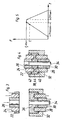
- Figure 1 shows a stamp 10 and a die 12 not otherwise shown, hydraulic calibration press.
- a hydraulic piston-cylinder unit 14 for driving the stamp 10 is shown symbolically. Instead of one Stamp or pressing force is a hydraulic pressure in a cylinder of the piston-cylinder unit 14 remains measurable with a pressure sensor 16. It is not necessary, the hydraulic pressure proportional to the punch or pressing force in the Convert force. Furthermore, a position of the stamp 10 with respect to FIG the die 12 can be measured with a distance measuring device 18.
- a molded part 20 to be calibrated is inserted into the die 12 and the punch 10 is first moved according to the method according to the invention into a predetermined pressing position s 1 , which is indicated in FIG. 1 with a broken line.
- the position s 1 is close to a target end position s 0 of the stamp 10.
- the target end position s 0 is that position of the stamp 10 in which a molded part 20, which has a target thickness before the pressing, after the pressing / calibration also has a nominal thickness, the nominal thickness after pressing / calibrating being smaller than before pressing / calibrating.
- the punch 10 is stopped at position s 1 and the hydraulic pressure in the piston-cylinder unit 14 is measured as a function of the punch position s 1 .
- measurements are taken during the compression / pressing process in order not to waste time.
- a correction value (abbreviated: corr.) Is calculated for the end position s 0 of the stamp 10 and the stamp 10 is then moved into the calculated end position s 0 + corr.
- the correction value is determined in such a way that the molded part 20 has the desired target thickness after the pressing / calibration.
- the punch 10 must be moved beyond the target end position s 0 , that is to say the molded part 20 is pressed more strongly in order to achieve the target thickness after pressing / calibration exhibit.
- the stamping force and the hydraulic pressure in the piston-cylinder unit 14 at the stamp position s 1 are greater than in the case of a molded part 20 which has the desired thickness before pressing.
- the punch 10 is not moved to the target end position s 0 , but less far, so that the molded part 20 also in this case after pressing / calibrating Has target thickness.
- the hydraulic pressure in the piston-cylinder unit 14 at the punch position s 1 is smaller than in the case of a molded part 20 which has the target thickness before the pressing. In this case the correction value is negative.
- the stamp position s 1 at which the hydraulic pressure in the piston-cylinder unit 14 is measured, is selected such that the stamp 10 has in no way passed its corrected end position.
- the stamp path s over time t is shown in FIG. 2.
- the correction value is determined on a trial basis by pressing tolerance-affected molded parts 20 in such a way that they have the desired thickness after the pressing.
- the punch 10 is stopped in position s 1 and the hydraulic pressure at this punch position and the end position of the punch 10 required to achieve the desired thickness are measured.
- the thickness of the pressed / calibrated molded parts 20 can be measured at random and, if necessary, the correction value can be changed in order to permanently ensure the desired thickness of the molded part 20 after the pressing / calibration with a small tolerance.
- the stamp 10 After pressing / calibrating, the stamp 10 is moved back and that calibrated molding 20 is with ejection pins 21 or with a lower stamp 23, as indicated by dashed lines in Figure 1, ejected.
- Figures 3 and 4 show stamps 22, 24, 26, 28, 30 and a die 32 one in the Other, not shown, hydraulic powder press in the open ( Figure 3) and closed ( Figure 4) position.
- the powder press has three tubular, nested upper punches 22, 24, 26 and two tubular, nested lower punches 28, 30 which lie in the die 32. In an inner, lower punch 30, a central pin 34 is received.
- a powder press With the A powder press becomes a metal powder 36 which is filled into the die 32, pressed into a molded part or compact 38, as shown in FIG or sintered.
- metal powder 36 ceramic powder, ferrite powder, Tungsten carbide powder or another powder are pressed or sintered. The The list is not exhaustive.
- the molded part 38 is a wheel with a hub 40, a wheel disc 42 and a rim 44 on the circumference.
- the hub 40 and the wheel rim 44 protrude axially on both sides over the wheel disc 42, which is the wheel symmetrical to a radial median plane.
- the punches 22, 24, 26, 28, 30 are moved according to the invention in such a way that each punch 22, 24, 26, 28, 30 reaches a target end position with respect to the die 32 approximately simultaneously.
- the stamp or pressing force or instead of the force of the hydraulic pressure exerted on the respective stamp 22, 24, 26, 28, 30 is measured when a predetermined stamp position is reached, and a correction value is determined which corresponds to a target final force F 0 or a target final pressure is added.
- the correction value is determined for those punches 22, 26, 30 of the powder press which press the wheel hub 40 and the wheel rim 44 and whose dimensional accuracy is high.
- the correction value can be calculated for all stamps 22, 26, 30 when one of the stamps 22, 26, 30 reaches the predetermined position s 1 or the correction value can be determined for each stamp 22, 26, 30 when the respective stamp 22, 26 , 30 reaches a predetermined stamp position.
- the correction value is determined in such a way that the wheel hub 40 and the wheel rim 44 have a desired thickness after the pressing.
- a negative correction value is determined and the stamp 22 pressing the wheel rim 44 is subjected to a pressure which is lower than the target final pressure.
- the correction values are determined experimentally and checked in series production by measuring the dimensional accuracy of the molded part 38 and changed if necessary.
- the stamp position of the stamps 26, 30 pressing the wheel hub 40 can additionally be corrected.
- the pressing force distribution of a stamp, for example stamp 26, is shown in FIG.
Landscapes
- Engineering & Computer Science (AREA)
- Mechanical Engineering (AREA)
- Powder Metallurgy (AREA)
- Forging (AREA)
Applications Claiming Priority (2)
| Application Number | Priority Date | Filing Date | Title |
|---|---|---|---|
| DE10301224 | 2003-01-15 | ||
| DE2003101224 DE10301224A1 (de) | 2003-01-15 | 2003-01-15 | Verfahren zur Endpositionsregelung einer Presse für maßgenaue Formkörper |
Publications (2)
| Publication Number | Publication Date |
|---|---|
| EP1439055A2 true EP1439055A2 (fr) | 2004-07-21 |
| EP1439055A3 EP1439055A3 (fr) | 2005-07-20 |
Family
ID=32519972
Family Applications (1)
| Application Number | Title | Priority Date | Filing Date |
|---|---|---|---|
| EP03028403A Withdrawn EP1439055A3 (fr) | 2003-01-15 | 2003-12-11 | Méthode pour la régulation de la position finale dans une presse pour des articles moulés ayant une dimension exacte |
Country Status (2)
| Country | Link |
|---|---|
| EP (1) | EP1439055A3 (fr) |
| DE (1) | DE10301224A1 (fr) |
Cited By (2)
| Publication number | Priority date | Publication date | Assignee | Title |
|---|---|---|---|---|
| EP2123435A4 (fr) * | 2007-03-20 | 2013-03-06 | Tungaloy Corp | Procédé de moulage par compression de plaquette jetable |
| EP3072688A1 (fr) * | 2015-03-26 | 2016-09-28 | Bundesdruckerei GmbH | Procede et dispositif destine a laminer un document de securite multicouches comprenant une surveillance de deformation |
Families Citing this family (4)
| Publication number | Priority date | Publication date | Assignee | Title |
|---|---|---|---|---|
| DE102009004620A1 (de) * | 2009-01-15 | 2010-07-22 | Gkn Sinter Metals Holding Gmbh | Verfahren zum Betrieb einer Pressvorrichtung zur Herstellung von Presslingen konstanter Höhe aus pulverförmigen Stoffen, Steuergerät für eine derartige Pressvorrichtung und Pressvorrichtung |
| DE102010008986A1 (de) * | 2010-02-24 | 2011-08-25 | Dorst Technologies GmbH & Co. KG, 82431 | Verfahren zur Pressparameteranpassung einer Keramik- oder Metallpulverpresse und Keramik- oder Metallpulverpresse zum Durchführen des Verfahrens |
| DE102014107127B4 (de) * | 2014-05-20 | 2016-09-15 | Fette Compacting Gmbh | Pulverpresse |
| DE102018107637A1 (de) | 2018-03-29 | 2019-10-02 | Dorst Technologies Gmbh & Co. Kg | Kalibrierverfahren |
Family Cites Families (7)
| Publication number | Priority date | Publication date | Assignee | Title |
|---|---|---|---|---|
| SE460460B (sv) * | 1983-07-01 | 1989-10-16 | Convey Teknik Ab | Foerfarande och anordning foer reglerad pressning av pulvermaterial |
| DE3715077A1 (de) * | 1987-05-06 | 1988-12-01 | Netzsch Maschinenfabrik | Verfahren zum steuern einer presse |
| DE3919821C2 (de) * | 1989-06-15 | 1994-04-07 | Mannesmann Ag | Verfahren und Vorrichtung zum Herstellen von maßhaltigen Preßlingen |
| DE3919847A1 (de) * | 1989-06-15 | 1990-12-20 | Mannesmann Ag | Verfahren und vorrichtung zur herstellung masshaltiger presslinge |
| DE3930475A1 (de) * | 1989-09-12 | 1991-03-14 | Dorst Masch & Anlagen | Presse zur herstellung masshaltiger presslinge aus pulverfoermigem material |
| DE19717217C2 (de) * | 1997-04-24 | 1999-12-02 | Fette Wilhelm Gmbh | Verfahren und Vorrichtung zur Herstellung von Preßlingen aus Hartmetall, Keramik, Sintermetall oder dergleichen |
| DE19846210A1 (de) * | 1998-10-07 | 2000-04-13 | Dorst Masch & Anlagen | Presse zum Herstellen von Formkörpern |
-
2003
- 2003-01-15 DE DE2003101224 patent/DE10301224A1/de not_active Ceased
- 2003-12-11 EP EP03028403A patent/EP1439055A3/fr not_active Withdrawn
Cited By (2)
| Publication number | Priority date | Publication date | Assignee | Title |
|---|---|---|---|---|
| EP2123435A4 (fr) * | 2007-03-20 | 2013-03-06 | Tungaloy Corp | Procédé de moulage par compression de plaquette jetable |
| EP3072688A1 (fr) * | 2015-03-26 | 2016-09-28 | Bundesdruckerei GmbH | Procede et dispositif destine a laminer un document de securite multicouches comprenant une surveillance de deformation |
Also Published As
| Publication number | Publication date |
|---|---|
| EP1439055A3 (fr) | 2005-07-20 |
| DE10301224A1 (de) | 2004-08-05 |
Similar Documents
| Publication | Publication Date | Title |
|---|---|---|
| EP0403038B1 (fr) | Procédé et dispositif pour fabriquer des articles pressés à dimensions exactes | |
| DE69309610T2 (de) | Verfahren und Vorrichtung zum Messen und Einstellen der Presskräfte an einer Presse | |
| DE102011101294B4 (de) | Vorrichtung und Verfahren zum Kalibrieren und Abgleichen einer Messeinrichtung einer Tablettenpresse sowie Tablettenpresse | |
| DE69509818T2 (de) | Verfahren und Gerät zur Optimierung der Betriebsbedingungen einer Presse auf der Basis der Pressebetriebsumgebung und/oder des Blechzustandes | |
| EP2149450B1 (fr) | Presse à poudre | |
| EP2361758B1 (fr) | Procédé d'adjustement des paramètres de pressage d'une presse à poudre céramique ou métallique et presse à poudre céramique ou métallique destinée à l'exécution du procédé | |
| EP0399296B1 (fr) | Justification automatique d'un laminoir universel après le changement des cylindres pour les profils neufs | |
| DE4209767C1 (fr) | ||
| EP1439055A2 (fr) | Méthode pour la régulation de la position finale dans une presse pour des articles moulés ayant une dimension exacte | |
| EP0353479A1 (fr) | Procédé et dispositif pour réduire la charge de presse dans une presse à découper comportant des butées fixes | |
| EP2428787B1 (fr) | Procédé et dispositif de calibrage d'un amplificateur de charge d'une chaîne de mesure piézoélectrique | |
| DE10010671A1 (de) | Verfahren zur Herstellung von Preßteilen durch Pressen von Metallpulver und anschließendes Sintern des Preßlings | |
| EP1277564B1 (fr) | Procédé de compression de matériaux en poudre | |
| EP2977196B1 (fr) | Procede de moulage a compensation d'erreurs de positionnement lors du processus de moulage et presse destinee a executer un tel procede | |
| CH716048B1 (de) | Verfahren sowie eine Messeinrichtung zum Ausmessen von Utensilien für Pressen. | |
| DE102022100935A1 (de) | Verfahren und Stanzmaschine zum Ermitteln einer Stempelaufsetzposition eines Stempels der Stanzmaschine | |
| EP1714775A2 (fr) | Procédé et appareil pour la simulation le mouvement avec friction d'au moins un poinçon supérieur et/ou d'au moins un poinçon inférieur dans une presse pour comprimés à table rotative | |
| EP1053863B1 (fr) | Dispositif pour la fabrication des pièces moulées | |
| EP2946917A1 (fr) | Presse à poudre | |
| EP1346821B1 (fr) | Machine de mesure de la position pour une presse à poudre | |
| EP3774136A1 (fr) | Procédé d'étalonnage | |
| DE102006058269A1 (de) | Verfahren zur Kalibrierung und/oder Überwachung mindestens eines Drucksensors und entsprechender Drucksensor | |
| AT520716B1 (de) | Vorrichtung und verfahren zum vermessen von elektrischen maschinen | |
| DE102024128564A1 (de) | Verfahren und Vorrichtung zum Durchsetzfügen | |
| CH689299A5 (de) | Verfahren und Vorrichtung zur maschinellen Verformung von Verbindungselementen. |
Legal Events
| Date | Code | Title | Description |
|---|---|---|---|
| PUAI | Public reference made under article 153(3) epc to a published international application that has entered the european phase |
Free format text: ORIGINAL CODE: 0009012 |
|
| AK | Designated contracting states |
Kind code of ref document: A2 Designated state(s): AT BE BG CH CY CZ DE DK EE ES FI FR GB GR HU IE IT LI LU MC NL PT RO SE SI SK TR |
|
| AX | Request for extension of the european patent |
Extension state: AL LT LV MK |
|
| PUAL | Search report despatched |
Free format text: ORIGINAL CODE: 0009013 |
|
| AK | Designated contracting states |
Kind code of ref document: A3 Designated state(s): AT BE BG CH CY CZ DE DK EE ES FI FR GB GR HU IE IT LI LU MC NL PT RO SE SI SK TR |
|
| AX | Request for extension of the european patent |
Extension state: AL LT LV MK |
|
| 17P | Request for examination filed |
Effective date: 20051026 |
|
| AKX | Designation fees paid |
Designated state(s): AT BE BG CH CY CZ DE DK EE ES FI FR GB GR HU IE IT LI LU MC NL PT RO SE SI SK TR |
|
| STAA | Information on the status of an ep patent application or granted ep patent |
Free format text: STATUS: THE APPLICATION IS DEEMED TO BE WITHDRAWN |
|
| 18D | Application deemed to be withdrawn |
Effective date: 20060529 |