EP1439125A2 - Banderoler - Google Patents
Banderoler Download PDFInfo
- Publication number
- EP1439125A2 EP1439125A2 EP03028393A EP03028393A EP1439125A2 EP 1439125 A2 EP1439125 A2 EP 1439125A2 EP 03028393 A EP03028393 A EP 03028393A EP 03028393 A EP03028393 A EP 03028393A EP 1439125 A2 EP1439125 A2 EP 1439125A2
- Authority
- EP
- European Patent Office
- Prior art keywords
- film
- film web
- web
- working
- supply
- Prior art date
- Legal status (The legal status is an assumption and is not a legal conclusion. Google has not performed a legal analysis and makes no representation as to the accuracy of the status listed.)
- Granted
Links
- 238000003466 welding Methods 0.000 claims abstract description 50
- 238000007789 sealing Methods 0.000 claims abstract description 30
- 239000000463 material Substances 0.000 claims abstract description 8
- 238000010438 heat treatment Methods 0.000 claims description 60
- 238000000034 method Methods 0.000 claims description 40
- 239000011888 foil Substances 0.000 claims description 37
- 238000000926 separation method Methods 0.000 claims description 28
- 238000003860 storage Methods 0.000 claims description 17
- 238000012432 intermediate storage Methods 0.000 claims description 7
- 230000001960 triggered effect Effects 0.000 claims description 5
- 238000005520 cutting process Methods 0.000 claims description 4
- 229920002379 silicone rubber Polymers 0.000 claims description 4
- 239000004945 silicone rubber Substances 0.000 claims description 4
- 230000000712 assembly Effects 0.000 claims description 3
- 238000000429 assembly Methods 0.000 claims description 3
- 230000015572 biosynthetic process Effects 0.000 claims description 2
- 239000002699 waste material Substances 0.000 abstract description 5
- 230000008901 benefit Effects 0.000 description 7
- 238000011161 development Methods 0.000 description 5
- 238000002955 isolation Methods 0.000 description 4
- 238000001816 cooling Methods 0.000 description 3
- 239000004698 Polyethylene Substances 0.000 description 2
- 238000013461 design Methods 0.000 description 2
- 210000003746 feather Anatomy 0.000 description 2
- 238000004519 manufacturing process Methods 0.000 description 2
- 238000012858 packaging process Methods 0.000 description 2
- -1 polyethylene Polymers 0.000 description 2
- 229920000573 polyethylene Polymers 0.000 description 2
- 244000043261 Hevea brasiliensis Species 0.000 description 1
- 239000004809 Teflon Substances 0.000 description 1
- 229920006362 Teflon® Polymers 0.000 description 1
- 208000027418 Wounds and injury Diseases 0.000 description 1
- 238000007596 consolidation process Methods 0.000 description 1
- 230000006378 damage Effects 0.000 description 1
- 230000000994 depressogenic effect Effects 0.000 description 1
- 230000000694 effects Effects 0.000 description 1
- 208000014674 injury Diseases 0.000 description 1
- 239000002184 metal Substances 0.000 description 1
- 229920003052 natural elastomer Polymers 0.000 description 1
- 229920001194 natural rubber Polymers 0.000 description 1
- 238000012856 packing Methods 0.000 description 1
- 238000004091 panning Methods 0.000 description 1
- 238000005096 rolling process Methods 0.000 description 1
- 238000007711 solidification Methods 0.000 description 1
- 230000008023 solidification Effects 0.000 description 1
- 230000003068 static effect Effects 0.000 description 1
- 239000006228 supernatant Substances 0.000 description 1
Images


Classifications
-
- B—PERFORMING OPERATIONS; TRANSPORTING
- B65—CONVEYING; PACKING; STORING; HANDLING THIN OR FILAMENTARY MATERIAL
- B65H—HANDLING THIN OR FILAMENTARY MATERIAL, e.g. SHEETS, WEBS, CABLES
- B65H19/00—Changing the web roll
- B65H19/10—Changing the web roll in unwinding mechanisms or in connection with unwinding operations
- B65H19/20—Cutting-off the expiring web
-
- B—PERFORMING OPERATIONS; TRANSPORTING
- B65—CONVEYING; PACKING; STORING; HANDLING THIN OR FILAMENTARY MATERIAL
- B65B—MACHINES, APPARATUS OR DEVICES FOR, OR METHODS OF, PACKAGING ARTICLES OR MATERIALS; UNPACKING
- B65B9/00—Enclosing successive articles, or quantities of material, e.g. liquids or semiliquids, in flat, folded, or tubular webs of flexible sheet material; Subdividing filled flexible tubes to form packages
- B65B9/02—Enclosing successive articles, or quantities of material between opposed webs
- B65B9/026—Enclosing successive articles, or quantities of material between opposed webs the webs forming a curtain
-
- B—PERFORMING OPERATIONS; TRANSPORTING
- B65—CONVEYING; PACKING; STORING; HANDLING THIN OR FILAMENTARY MATERIAL
- B65H—HANDLING THIN OR FILAMENTARY MATERIAL, e.g. SHEETS, WEBS, CABLES
- B65H19/00—Changing the web roll
- B65H19/10—Changing the web roll in unwinding mechanisms or in connection with unwinding operations
- B65H19/18—Attaching, e.g. pasting, the replacement web to the expiring web
- B65H19/1842—Attaching, e.g. pasting, the replacement web to the expiring web standing splicing, i.e. the expiring web being stationary during splicing contact
- B65H19/1852—Attaching, e.g. pasting, the replacement web to the expiring web standing splicing, i.e. the expiring web being stationary during splicing contact taking place at a distance from the replacement roll
-
- B—PERFORMING OPERATIONS; TRANSPORTING
- B65—CONVEYING; PACKING; STORING; HANDLING THIN OR FILAMENTARY MATERIAL
- B65H—HANDLING THIN OR FILAMENTARY MATERIAL, e.g. SHEETS, WEBS, CABLES
- B65H19/00—Changing the web roll
- B65H19/10—Changing the web roll in unwinding mechanisms or in connection with unwinding operations
- B65H19/18—Attaching, e.g. pasting, the replacement web to the expiring web
- B65H19/1857—Support arrangement of web rolls
- B65H19/1873—Support arrangement of web rolls with two stationary roll supports carrying alternately the replacement and the expiring roll
-
- B—PERFORMING OPERATIONS; TRANSPORTING
- B65—CONVEYING; PACKING; STORING; HANDLING THIN OR FILAMENTARY MATERIAL
- B65H—HANDLING THIN OR FILAMENTARY MATERIAL, e.g. SHEETS, WEBS, CABLES
- B65H2301/00—Handling processes for sheets or webs
- B65H2301/40—Type of handling process
- B65H2301/46—Splicing
- B65H2301/462—Form of splice
- B65H2301/4621—Overlapping article or web portions
-
- B—PERFORMING OPERATIONS; TRANSPORTING
- B65—CONVEYING; PACKING; STORING; HANDLING THIN OR FILAMENTARY MATERIAL
- B65H—HANDLING THIN OR FILAMENTARY MATERIAL, e.g. SHEETS, WEBS, CABLES
- B65H2301/00—Handling processes for sheets or webs
- B65H2301/40—Type of handling process
- B65H2301/46—Splicing
- B65H2301/463—Splicing splicing means, i.e. means by which a web end is bound to another web end
- B65H2301/4634—Heat seal splice
-
- B—PERFORMING OPERATIONS; TRANSPORTING
- B65—CONVEYING; PACKING; STORING; HANDLING THIN OR FILAMENTARY MATERIAL
- B65H—HANDLING THIN OR FILAMENTARY MATERIAL, e.g. SHEETS, WEBS, CABLES
- B65H2511/00—Dimensions; Position; Numbers; Identification; Occurrences
- B65H2511/10—Size; Dimensions
- B65H2511/14—Diameter, e.g. of roll or package
-
- B—PERFORMING OPERATIONS; TRANSPORTING
- B65—CONVEYING; PACKING; STORING; HANDLING THIN OR FILAMENTARY MATERIAL
- B65H—HANDLING THIN OR FILAMENTARY MATERIAL, e.g. SHEETS, WEBS, CABLES
- B65H2701/00—Handled material; Storage means
- B65H2701/10—Handled articles or webs
- B65H2701/17—Nature of material
- B65H2701/175—Plastic
- B65H2701/1752—Polymer film
-
- Y—GENERAL TAGGING OF NEW TECHNOLOGICAL DEVELOPMENTS; GENERAL TAGGING OF CROSS-SECTIONAL TECHNOLOGIES SPANNING OVER SEVERAL SECTIONS OF THE IPC; TECHNICAL SUBJECTS COVERED BY FORMER USPC CROSS-REFERENCE ART COLLECTIONS [XRACs] AND DIGESTS
- Y10—TECHNICAL SUBJECTS COVERED BY FORMER USPC
- Y10T—TECHNICAL SUBJECTS COVERED BY FORMER US CLASSIFICATION
- Y10T156/00—Adhesive bonding and miscellaneous chemical manufacture
- Y10T156/10—Methods of surface bonding and/or assembly therefor
- Y10T156/1052—Methods of surface bonding and/or assembly therefor with cutting, punching, tearing or severing
- Y10T156/1054—Methods of surface bonding and/or assembly therefor with cutting, punching, tearing or severing and simultaneously bonding [e.g., cut-seaming]
Definitions
- the invention relates to a banding machine with one on both sides Feed table arranged film rolls, the film webs under Formation of a through a slot of the feed table, Foil curtain are connected to each other by a sealed seam, in which the goods to be banded are pushed against the film curtain, the Put a loop around the material and the loop by means of one, at least one of the film webs temporarily clamping tightening device tightened and by means of a Welding device is welded and separated from the remainder of the film.
- Such a banding machine is for example from DE 25 34 156 known.
- a disadvantage of the known banding machine is that the Packing process when changing the foils for two to three minutes must be interrupted.
- Banding machines continue to be state of the art known in which the film change takes place automatically. Thereby in the beginning of the supply film web exactly positioned and in a second step with the working film web welded. In a third step, the old one is made Working film web from the new working film web by means of a knife Cut. If the supply film web was not positioned exactly, it can be necessary that also the excess film sheet is separated, for example, by means of a knife. In this case, falls Film waste.
- the banding machine from the state of the art has several disadvantages. For one thing, it is necessary that the beginning the supply film web is positioned exactly to avoid a Film overhang is created. Should the supply film web not be exact positioned, it is necessary to remove the excess film to cut off. Another disadvantage of the banding machine is that a welding device and a separating device separate therefrom to separate the old working film web from the new working film web must be provided.
- the invention is therefore based on the object Propose a banding machine in which the supply film web is not must be positioned exactly and with no loose film waste
- the object underlying the invention is achieved in that at least on one side of the feed table, especially on both Feed table sides, a film changing unit is provided from at least one supply film roll and one working film roll, where both the working film web and the storage film web by a preferably two, foil sealing units is guided, the Foil sealing unit at least one separation welding device for Production of a squeeze separating seam between the old working foil web and Supply film web and between the supply film web overhang and the Remaining of the old working film web in one operation.
- the Banding machine it is possible that a automatic film change is made without the Packaging process must be interrupted.
- a separation welding device ensures that the supply film web and weld the working film web to a new working film web and that at the same time the supply film overhang with the old one Working film web is welded.
- the separation of the film webs takes place in the same work step as welding the Film ends.
- the invention is also based on the object of a method for Carrying out a film change in an inventive Propose a banding machine in which there are no loose film residues attack.
- This object is achieved in that the supply film roll on a appropriate holder is placed and that the supply film web through an associated first film slot between the first and the middle component of the film sealing unit is guided to the middle component is guided around, and through a second film slot is guided through which the working film web also runs, the Afterwards, the supply film protrusion with a clamping mechanism is clamped, whereupon the Storage film web and the adjacent working film web by means of the Separation welding device separated and in the same step between two components the old working film web with the supply film web and the excess film web overhang with the rest of the old working film web are welded by means of the separation welding device, whereupon the old working film roll replaced by a new supply film roll becomes. Then proceed as described again.
- the method according to the invention has the advantage that there is no loose film waste arises because at the same time as the production of the new working film web, consisting of old working film web and storage film web, the Storage film web protrusion with the rest of the old working film web is welded.
- An advantageous embodiment provides that the film sealing unit of two, preferably arranged side by side, Separation welding devices, each with a film slot, which are arranged such that essentially three through the two, preferably parallel, film slots separate components are formed, the supply film web through both film slots is guided and partially wraps around the middle component and that Working film web through one of the two film slots, preferably in Essentially vertical; is led.
- This advantageous embodiment of the Foil sealing unit enables easy handling when threading the new supply film web. This only has to go through the two parallel ones Slots are guided. On an exact positioning of the film in Direction of travel can be omitted because the excess film overlap with the separating welding device to the rest of the old working film web is welded on.
- the film sealing unit is either of the two Separation welding devices distributed over two components. All components are encased by a smooth housing to ensure the smoothest possible To ensure sliding of the film webs. It is an advantage Working film web vertically through one or the other Foil slot guided to cause as little friction loss as possible.
- An expedient embodiment provides that each of the two Separation welding devices from each other through a film slot there are separate modules, namely a heating element and a Counter tool, two on the counter tool or on the heating element spaced clamping strips, preferably made of silicone rubber, are provided and that either on the heating element or on the Counter tool a separating edge is provided, at least one the two modules can be moved towards the other.
- each Separation welding device is on two components of the film sealing unit distributed. At least one of the assemblies, i.e. either the heating element or the counter tool can be moved towards each other.
- the separating edge on the heating elements is provided, the heating elements being static in the central component of the Foil sealing unit are attached and that the separating edges are each in Direction of the associated film slot are aligned and that in every other component a counter tool with rubber-like Separating profiles is provided in the direction of the central component is movable.
- the counter tools are with a piston rod a pneumatic or hydraulic cylinder connected to the movement allows.
- the counter tool is on top of each other To move film webs. These are by means of clip strips jammed, whereupon the further movement of the counter tool Foil webs are pressed against the cutting edge, causing it to separation of the film webs comes.
- By moving the Counter tool reaches the counter tool with the separating profiles Attachment to the heating element.
- the ends of the film in between are welded.
- the shape of the separating profile is based on the shape of the Heating element adjusted to get two optimal welds. After the cutting and welding process, the counter tool moved back towards its original position.
- each heating element in In the direction of the film slot a spring plate with an opening for clamping the Foil sheets is stored before the separation welding process, the Sheets of film between the counter tool with clamping strips and the Plate can be clamped.
- the counter tool with the clamping strip in the direction of the plate and thus clamps the two superimposed film webs between clamping strips and plate one.
- the film web ends are welded. It is an advantage Heating element coated with Teflon.
- the heating element is advantageously like this built that it tends to a sharp separation edge and that the as The sides of the elongated separating edge serving as welding surfaces are concave are bent. As a result, an optimal system as The sides of the separating edge on the separating profile serving welding surfaces reached.
- Counter tool made of a rail made of rubber-like material, preferably silicone rubber, is formed, on which Protruding areas for clamping the film and front surface for separating the superimposed foils as well as with something backward areas for sealing the old working film web and the supply film web are provided.
- the Heating element surface to be adjusted so that the function of each Areas of the counter tool front surface is guaranteed.
- the heating element can be pulse heated, consists of a thin metal plate that heats up in no time can be. It is advantageous for any configuration of the heating element No cooling device necessary, because the film rolls, depending on the thickness to be changed only once per hour, so that is long enough There is a cooling time for cooling the heating element.
- the clamping mechanism consists of a Ledge, which is spring-loaded against the underside of the middle Component of the film sealing unit can be pressed, with a magnet for Fixing the bar in an open position is provided.
- the Storage film web is inserted into both film slots as described above threaded and then clamped.
- the terminal block is preferably by hand moved against the spring force, so that the separated, with the rest of the working film web welded supply film overhang with the The rest of the old working film can be removed.
- the Clamping strip by means of one or more magnets in an open position held so that the clamping mechanism for threading the new Storage film web does not have to be opened again.
- the work film web by a Foil web intermediate storage device is guided.
- the device is intended to ensure that the packaging process during the welding process between the old film and Supply film web can continue to be operated. During this time the required working film from the film web intermediate storage device based.
- the Film web intermediate storage device from a one-sided Foil rocker exists, being on the rocker and one Housing wall of the banding machine provided film guide rollers are, the working film web alternately around the guide rollers the housing wall and around the guide rollers on the foil rocker is. Because during the welding and solidification process of the new Working roll no film web can be removed, the Working film web from the film web buffer device based. The rocker moves in the direction of Guide rollers on the housing wall.
- the film web is similar to that Pulley principle guided between the rollers.
- Benefit from that Foil rolls, preferably pneumatic drum brakes, are provided. These are usually active to prevent unintended unrolling To prevent film web. So that the banding process by a unintentional tearing of the working film web is not interrupted, is advantageously provided that the foil rocker when a certain rocker angle triggers a switch with which the preferably air operated, film roller brakes are operated.
- a spaced from the film sealing unit pivotable working film guide roller is provided in two Positions is pivotable, which are characterized in that the Working film depending on which film slot it is currently being guided through is always along the outer edge of the film slot. This is ensures that the inner film slot edge, i.e. the edge on the middle component, is free, so that the supply film web along this inner edge can be laid.
- a device for continuous determination of the roll thickness in particular in the form of a Light button, for outputting a control signal for triggering the Foil clamping process and / or the heating process for heating of the corresponding heating element is provided.
- Continuous scanning of the film roll thickness ensures that the Film clamping process and / or the heating process in good time are triggered before the working film web completely from the Working film roll is unwound.
- a temperature sensor for outputting a control signal for the triggering of the separation welding process, when one is reached Desired temperature, preferably 180 degrees, is provided.
- Desired temperature preferably 180 degrees
- the Temperature sensor ensures that the separation welding process is triggered immediately after the required temperature has been reached, so that there is no loss of time.
- the optimal temperature of the heating element in a range of approx. 170 ° C fluctuate up to approx. 220 ° C. The optimal temperature depends on the material.
- the supply roll and the Working film roll do not have their own drive.
- the foil webs only by feeding the goods into the foil curtain unrolled. It is both with the working film roll and with the Supply film roll brakes, preferably pneumatic brakes, provided to ensure that the film webs under one certain tension. Furthermore, an unintentional rolling should be avoided.
- the Brakes can be released if necessary, i.e. if the film needs to be replenished. As a rule, the brakes are closed. Only if through movement the switch is actuated, the brakes are released.
- a separation welding process comprises the following steps: First, this is Counter tool moved in the direction of the spring plate. There is one Clamping the supply film web and the one lying against it Working film web between the clamping strips of the counter tool and the sprung plate with opening. In the event of complete Design of the counter tool made of rubber-like material can the sprung plate can be dispensed with. Before, during or after The heating element heats up. After one Set temperature is reached, the spring-loaded plate is by means of Counter tool against the spring force in the direction of the heating element About suppressed. The heating element with separating edge pierces the opening the sprung plate. The overlapping foil webs are separated and the superimposed ends are each welded.
- the method provides that the working film guide role of a first position into a second position, by means of a Air cylinder is pivoted so that the new working film web runs along the outer edge of the film slot. This Panning takes place immediately after the clamping of the Foil sheets on the plate was released.
- the film clamping process and the Heating the corresponding heating element by issuing a Control signal of the device for determining the film roll thickness is triggered when the working film roll has a minimum thickness below. This ensures optimal material utilization. The right moment to change the film roll cannot be missed become.
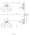
- a banding machine 1 is shown schematically in FIG. In the In the middle of the drawing is a feed table 2. To everyone Working table webs 3 are located on the feed table side Sealing seam are connected to a film curtain 4. The foil curtain 4 passes through a slot 5 of the feed table 2. The not shown banding goods are pushed against the film curtain. The Foil curtain wraps around a loop, not shown Good around. The loop is fastened by means of one of the working film webs 3 temporarily tightening tightening device 6 and tightened welded by means of a welding device, not shown, and from Film residue separated. A combined comes with advantage here too Separation welding process for use.
- Each Foil changing unit 7 has a supply foil roll 8 and one Working film roll 9 on. Both film rolls 8.9 are on one Height and are rotatable.
- the working film webs 3 are through Moving the goods in the film curtain 4 from the working film rolls 9 deducted.
- a film sealing unit 10 is located above the film rolls 8, 9 appropriate.
- Foil rockers 11 designed foil web intermediate storage devices.
- the working film web 3 is alternating between film guide rollers 12 on the housing and film guide rollers 13 on the rocker 11 in the manner of a block and tackle - the film guide rollers 12, 13 cantilevered on one side, which is an easy threading of the Working film web 3 in the film web buffer device 11 allows.
- the film web intermediate storage device 11 ensures that the banding process also during the Foil roll change can be continued. During this time is the working film web 3 from the Film web buffer device and not directly from the Working film roll 9 related.
- the foil rocker 11 moves by Swivel joint 14 upwards and releases at a certain rocker angle a switch, not shown, which is also not shown Working film roll brake releases.
- the film changing unit 7 is shown in detail in FIG.
- the Foil sealing unit 10 consists of three components 15, 16, 17.
- the two outer components 15, 17 are each by a film slot 18, 19 from middle component separated.
- deflection rollers 20, 21, which ensure that both the film 3 and the Storage film web 22 essentially perpendicular into the film slots 18, 19 are introduced.
- the working film web 3 passes essentially over the deflection roller 21 vertically into the film slot 19 and there along the outer Slot side 23 led up and there over a Work film web guide roller 24 deflected.
- the Working film guide roller 24 is on a rotatably mounted lever 25 attached.
- the lever 25 and thus the work film guide roller 24 can with a piston rod 26 articulated on the lever 25 Cylinder 27 attached to the housing from a first position 28 in a second position 29 shown in Figure 3 can be moved. there positions 28, 29 are selected so that the respective working film web 3 essentially vertically through the respective film slot 18, 19 is guided to optimally thread the supply film web 22 guarantee.
- the supply film web 22 is as shown in Figure before the separation welding process 2 shown threaded. This happens in such a way that the supply film web inserted around the deflection roller 20 from below into the film slot 18 is guided around the component 16 at the top and then from the top to below through the film slot 19 along the inner slot side 30 to be led. Then the film supply web is by means of a Clamping mechanism 31 clamped.
- the clamping mechanism 31 consists of a strip 32 which is pressed against the component 16 by means of springs 33 is pressed. Between bar 32 and component 16, the Storage film web 22 are jammed. After completing the Isolation welding process is the supply film web projection 34 with the The rest of the old working film web is welded.
- the film sealing unit consists of essentially from two separating welding devices 36, 37.
- the structure of the separating welding devices 36 and 37 is shown in FIG 3 described in detail.
- a film roll change has already taken place in FIG.
- the Working film roll 9 is now on the left side, whereas the Storage film roll is arranged on the right.
- the supply roll is one Deflection roller 21 through the film slot 19 around the component 16 out and from there through the film slot 18 in the Clamping mechanism 31.
- the working film guide roller 24 is located in position 29, which ensures that the working film web 3 is guided along the outer slot side 38 of the film slot 18. This ensures that the supply film web without disability inserted through the working film web 3 into the film slots 18, 19 and can be jammed.
- the separating welding devices 36, 37 are arranged horizontally. she consist of a counter tool 39, 40, which by means of a Pneumatic cylinders 41, 42 can be moved in the direction of component 16, and of two heating elements 43, 44 arranged in component 16 Heating elements 43, 44 run on their associated film slot 18, 19 associated end pointed and there form a separating edge 45, 46. Die Surfaces to the side of the separating edges serve as welding surfaces.
- Each Heating element 43, 44 is a spring-loaded plate 47 in the direction of the film slot, 48 assigned. In the middle of the spring-loaded plates 47, 48 is located an opening 49, 50.
- the counter tools 39, 40 have two spaced clamping strips 51, 52 made of natural rubber. In the middle of the counter tools 39, 40 are adapted to the shape of the heating elements 43, 44 Separation profiles 53, 54 on which the heating elements 43, 44 after Sideways movement of the counter tools and the one another weld the ends of the film webs 3, 22 together.
- the old one runs empty Working film roll with the rest of the old working film web welded supply film overhang 34 removed and by a Storage foil roll 8 replaced. Thereafter, the supply film web 22 is as in 2 and 3 shown around the component 16 and clamped by means of a clamping mechanism 31.
- the roll thickness is determined using a light button. Will not be light reflected more in the direction of a sensor, the working film roll 9 is thus almost processed, a control signal is issued. This will Foil clamping process and the heating process for heating the corresponding heating element 43 or 44 triggered. The other The process will again be described with reference to FIG. 3.
- the Counter tool 39 is in the direction by means of the pneumatic cylinder 41 sprung plate 47 moves. The two lying on top of each other Film webs 3, 22 are against the plate by means of the clamping strips 51 47 pressed and thus jammed. This remains in this position Counter tool until that of a temperature sensor, not shown determined actual temperature of the heating element 43 of the target temperature (at Polyethylene about 180 ° C) is reached.
- the counter tool 39 is by means of of the pneumatic cylinder in the direction of its original Position shifted, but only so far that the two together welded film ends between plate 47 and Clamping strips 51 are jammed. This clamping after separation and welding is necessary to ensure that the Tighten squeeze seams sufficiently.
Landscapes
- Engineering & Computer Science (AREA)
- Mechanical Engineering (AREA)
- Basic Packing Technique (AREA)
- Containers And Plastic Fillers For Packaging (AREA)
- Pharmaceuticals Containing Other Organic And Inorganic Compounds (AREA)
- Packaging Of Annular Or Rod-Shaped Articles, Wearing Apparel, Cassettes, Or The Like (AREA)
- Lining Or Joining Of Plastics Or The Like (AREA)
- Replacement Of Web Rolls (AREA)
Applications Claiming Priority (2)
| Application Number | Priority Date | Filing Date | Title |
|---|---|---|---|
| DE10301347A DE10301347B4 (de) | 2003-01-16 | 2003-01-16 | Banderoliermaschine |
| DE10301347 | 2003-01-16 |
Publications (3)
| Publication Number | Publication Date |
|---|---|
| EP1439125A2 true EP1439125A2 (fr) | 2004-07-21 |
| EP1439125A3 EP1439125A3 (fr) | 2006-03-22 |
| EP1439125B1 EP1439125B1 (fr) | 2008-01-02 |
Family
ID=30775633
Family Applications (1)
| Application Number | Title | Priority Date | Filing Date |
|---|---|---|---|
| EP03028393A Expired - Lifetime EP1439125B1 (fr) | 2003-01-16 | 2003-12-11 | Banderoler |
Country Status (5)
| Country | Link |
|---|---|
| US (1) | US7147737B2 (fr) |
| EP (1) | EP1439125B1 (fr) |
| AT (1) | ATE382546T1 (fr) |
| DE (2) | DE10301347B4 (fr) |
| ES (1) | ES2297091T3 (fr) |
Cited By (2)
| Publication number | Priority date | Publication date | Assignee | Title |
|---|---|---|---|---|
| US7201952B2 (en) * | 2004-12-03 | 2007-04-10 | Xerox Corporation | Low voltage e-paper |
| CN109368335A (zh) * | 2018-12-05 | 2019-02-22 | 杭州佳鹏电脑科技股份有限公司 | 送纸切换方法、装置及系统 |
Families Citing this family (26)
| Publication number | Priority date | Publication date | Assignee | Title |
|---|---|---|---|---|
| DE102004032528C5 (de) * | 2004-07-06 | 2012-04-05 | Khs Gmbh | Verfahren zum Durchführen eines Rollenwechsels bei einer Versorgungseinheit zum Zuführen eines bahnartigen Flachmaterials an eine Verpackungsmaschine oder dergleichen Verarbeitungsmaschine sowie Versorgungseinheit zum Durchführen dieses Verfahrens |
| DE102006037189A1 (de) * | 2006-08-09 | 2008-02-14 | Khs Ag | Verfahren zum Durchführen eines Rollenwechsels bei einer Versorgungseinheit zum Zuführen eines bahnartigen Flachmaterials an eine Verpackungsmaschine oder dergleichen Verarbeitungsmaschine sowie Versorgungseinheit zum Durchführen dieses Verfahrens |
| CN101177169B (zh) * | 2006-11-07 | 2011-09-28 | 国家农产品保鲜工程技术研究中心(天津) | 多列立式旋转连续生产双效保鲜纸成型包装机 |
| US8146328B2 (en) * | 2007-01-16 | 2012-04-03 | Orihiro Engineering Co., Ltd | Film supply apparatus and filling and packaging system including the film supply apparatus |
| DE102010021732A1 (de) * | 2010-05-27 | 2011-12-01 | Krones Ag | Spleißvorrichtung und Verfahren zum Spleißen eines bahnartigen Flachmaterials |
| CN101913509B (zh) * | 2010-07-29 | 2011-11-30 | 哈尔滨博实自动化股份有限公司 | 自动更换m形筒形膜卷的方法 |
| CN102514765B (zh) * | 2012-01-09 | 2014-02-26 | 山东碧海机械有限公司 | 一种无菌纸盒灌装机的密封条不间断送条装置 |
| US9211481B2 (en) * | 2012-07-27 | 2015-12-15 | Nb Tech Inc. | Visual display system and method of constructing a high-gain reflective beam-splitter |
| DE102013110944A1 (de) | 2013-10-02 | 2015-04-02 | Krones Aktiengesellschaft | Verfahren und Vorrichtung zum Wechseln von Trägereinheiten mit auf Vorratsrollen aufgewickeltem flächigem Verpackungsmaterial innerhalb einer Verpackungsmaschine |
| US10351283B2 (en) * | 2015-12-17 | 2019-07-16 | Khs Usa, Inc. | Magnetically operated sealing bar assembly for packaging machines |
| US9956797B2 (en) * | 2016-03-02 | 2018-05-01 | OCE Holding B.V. | Web feeding of weak media |
| CN105831803A (zh) * | 2016-05-17 | 2016-08-10 | 新乡东方工业科技有限公司 | 一种卷烟纸静态拼接的双面胶与粘纸板安装结构 |
| CN106043810A (zh) * | 2016-07-08 | 2016-10-26 | 张家港市德顺机械有限责任公司 | 一种膜包机自动换膜装置 |
| CN106276361B (zh) * | 2016-09-09 | 2017-09-22 | 广州祺盈机械设备有限公司 | 一种应用于裹膜机的自动换膜机 |
| CN106865336B (zh) * | 2017-04-18 | 2023-02-28 | 山东威高血液净化制品股份有限公司 | 一种空心纤维膜直线式收丝方法及装置 |
| CN107161758B (zh) * | 2017-04-19 | 2023-11-17 | 佛山市宝索机械制造有限公司 | 纸卷封口方法和装置 |
| EP3636571A1 (fr) * | 2018-10-12 | 2020-04-15 | Heberlein AG | Appareil d'épissure destiné à l'épissure de fil et procédé de fabrication d'un appareil d'épissure |
| CN109399293B (zh) * | 2018-12-10 | 2024-07-02 | 无锡先导智能装备股份有限公司 | 接料装置 |
| DE102019203742A1 (de) * | 2019-02-07 | 2020-08-13 | Bhs Corrugated Maschinen- Und Anlagenbau Gmbh | Materialbahn-Einzugsvorrichtung |
| DE102019001174A1 (de) | 2019-02-18 | 2020-08-20 | Giesecke+Devrient Currency Technology Gmbh | Vorrichtung für die Verpackung von Blattgut |
| JP7387162B2 (ja) * | 2020-01-08 | 2023-11-28 | 大森機械工業株式会社 | スプライサー及びフィルム接合方法 |
| CN111301743B (zh) * | 2020-03-30 | 2025-02-18 | 浙江希望机械有限公司 | 一种高速薄膜捆扎机 |
| CN114408268B (zh) * | 2022-02-17 | 2022-11-08 | 湖北实美科技有限公司 | 一种铝型材产品覆膜设备 |
| FI130645B1 (en) * | 2023-01-04 | 2024-01-04 | Valmet Technologies Oy | Roll cutting machine and procedure for roll cutting a fiber web |
| WO2024234877A1 (fr) * | 2023-05-16 | 2024-11-21 | 南京永成包装自动化设备有限公司 | Appareil de coupe et de couture automatique pour assembler des extrémités de rouleaux de sac, et procédé d'assemblage par coupe et couture |
| CN118273369B (zh) * | 2024-04-26 | 2025-09-12 | 中国十七冶集团有限公司 | 一种超深帷幕截水垂直施工装置及方法 |
Family Cites Families (22)
| Publication number | Priority date | Publication date | Assignee | Title |
|---|---|---|---|---|
| DE7333907U (de) * | 1974-02-28 | Wickersheim Verpackungsmaschinen Gmbh & Co | Aus einem unteren und einem oberen Schweißbalken bestehende und eine Trenneinrichtung aufweisende Schweißeinriehtung für Vorrichtungen zur Herstellung und zum Verschließen von Beutelpackungen aus schlauchförmigem Material für stückige und Schütt-Güter | |
| GB1184591A (en) * | 1967-01-04 | 1970-03-18 | Lerner Machine Company Ltd | Apparatus for Supplying Wrapping Material of Thermoplastic Synthetic Resin to Wrapping Apparatus. |
| DE2223907A1 (de) * | 1972-05-17 | 1973-12-06 | Kuper Heinrich Fa | Vorrichtung zum trennen und wiederanschweissen von folienbahnen, insbesondere an folieneinschlagmaschinen |
| FR2198476A5 (en) * | 1972-09-01 | 1974-03-29 | Lara Sa | Appts for feeding weldable band from alternate reels - makes joint between old and new reels without stopping feed of band to next station |
| DE2534156A1 (de) * | 1975-07-31 | 1977-02-17 | Pester Platinen | Antriebseinrichtung fuer straffziehvorrichtungen von banderoliermaschinen |
| DE2537882C2 (de) * | 1975-08-26 | 1986-04-17 | Heinrich Kuper GmbH & Co KG, 4835 Rietberg | Vorrichtung zum Verpacken von Gegenständen in Folie |
| US4705601A (en) * | 1987-02-05 | 1987-11-10 | B.I. Industries, Inc. | Multi-ply paper forming fabric with ovate warp yarns in lowermost ply |
| US4894679A (en) * | 1988-06-03 | 1990-01-16 | Graphics Lx Corp. | Method and apparatus for use in transferring an image |
| GB8928799D0 (en) * | 1989-12-20 | 1990-02-28 | Du Pont Canada | Self voiding jaw for packaging machine |
| IT1241724B (it) * | 1990-06-06 | 1994-02-01 | Ricciarelli Garibaldo S R L | Metodo ed apparecchiatura per la giunzione di estremi di nastri di pellicola saldabile per la formazione di sacchetti ed altro |
| US5238536A (en) * | 1991-06-26 | 1993-08-24 | Huyck Licensco, Inc. | Multilayer forming fabric |
| IT227176Y1 (it) * | 1992-11-11 | 1997-09-15 | Ocme Srl | Dispositivo per la giunzione di film di materiale plastico termoestraibile in una macchina utilizzante detto film |
| US5514237A (en) * | 1993-10-05 | 1996-05-07 | The Procter & Gamble Company | Heat splicing of thermoplastic film |
| US5518042A (en) * | 1994-09-16 | 1996-05-21 | Huyck Licensco, Inc. | Papermaker's forming fabric with additional cross machine direction locator and fiber supporting yarns |
| JPH08108957A (ja) * | 1994-10-07 | 1996-04-30 | Shikoku Kakoki Co Ltd | テープ接続装置 |
| JP3569004B2 (ja) * | 1994-10-17 | 2004-09-22 | 日本テトラパック株式会社 | フィルム接合装置 |
| DE19522110A1 (de) * | 1995-06-19 | 1997-01-02 | Kisters Maschinenbau Gmbh | Verfahren zum Verschweißen zweier von jeweils einer Vorratsrolle kommender Folienbahnen in einer Verpackungsmaschine |
| GB9604602D0 (en) * | 1996-03-04 | 1996-05-01 | Jwi Ltd | Composite papermaking fabric with paired weft binder yarns |
| DE19715263A1 (de) * | 1997-04-12 | 1998-10-15 | Tetra Laval Holdings & Finance | Vorrichtung zum Trennsiegeln von Kunststoffolien |
| DE19921032A1 (de) * | 1999-05-06 | 2000-11-09 | Skinetta Pac Syst Kiener Gmbh | Verfahren und Vorrichtung zum Einschlagen eines Gutes mit einer Kunststofffolie |
| US6533213B2 (en) * | 2000-05-01 | 2003-03-18 | Kimberly-Clark Worldwide, Inc. | Method and apparatus for unwinding web materials |
| JP3902593B2 (ja) * | 2001-12-10 | 2007-04-11 | 大成ラミック株式会社 | フィルム連結装置および連結方法 |
-
2003
- 2003-01-16 DE DE10301347A patent/DE10301347B4/de not_active Expired - Lifetime
- 2003-12-11 AT AT03028393T patent/ATE382546T1/de not_active IP Right Cessation
- 2003-12-11 ES ES03028393T patent/ES2297091T3/es not_active Expired - Lifetime
- 2003-12-11 DE DE50308909T patent/DE50308909D1/de not_active Expired - Lifetime
- 2003-12-11 EP EP03028393A patent/EP1439125B1/fr not_active Expired - Lifetime
- 2003-12-23 US US10/746,016 patent/US7147737B2/en not_active Expired - Lifetime
Cited By (2)
| Publication number | Priority date | Publication date | Assignee | Title |
|---|---|---|---|---|
| US7201952B2 (en) * | 2004-12-03 | 2007-04-10 | Xerox Corporation | Low voltage e-paper |
| CN109368335A (zh) * | 2018-12-05 | 2019-02-22 | 杭州佳鹏电脑科技股份有限公司 | 送纸切换方法、装置及系统 |
Also Published As
| Publication number | Publication date |
|---|---|
| DE10301347B4 (de) | 2013-05-08 |
| US7147737B2 (en) | 2006-12-12 |
| EP1439125A3 (fr) | 2006-03-22 |
| DE50308909D1 (de) | 2008-02-14 |
| ES2297091T3 (es) | 2008-05-01 |
| EP1439125B1 (fr) | 2008-01-02 |
| ATE382546T1 (de) | 2008-01-15 |
| DE10301347A1 (de) | 2004-02-26 |
| US20040140044A1 (en) | 2004-07-22 |
Similar Documents
| Publication | Publication Date | Title |
|---|---|---|
| EP1439125A2 (fr) | Banderoler | |
| EP0093953B1 (fr) | Presse pour ballots de fibres avec dispositif de cerclage | |
| DE2457714B2 (de) | Vorrichtung zum überlappenden Verbinden des vorderen Endes eines Streifens einer Vorratswickelrolle mit dem Streifen einer ablaufenden Wickelrolle | |
| EP1922253B1 (fr) | Banderolage d'une pile d'objets | |
| EP1097038B1 (fr) | Dispositif pour souder des bandes en materiau thermoplastique | |
| EP0551244B1 (fr) | Liage de marchandises empilées au moyen d'une bande large | |
| CH695771A5 (de) | Vorrichtung zum Speichern und Abwickeln von bahnförmigen Materialien in Buchbindereimaschinen. | |
| DE69719686T2 (de) | Schneidvorrichtung in einer Form-Füll-Siegelmaschine | |
| DE2548786A1 (de) | Vorrichtung zum banderolenartigen umhuellen von verpackungsgegenstaenden mit kunststoffolie | |
| DE4212167C2 (de) | Verfahren und Vorrichtung zum Verbinden eines Papierbahn-Einfädelteiles mit einer Papierbahn | |
| WO1995035237A1 (fr) | Procede et dispositif permettant d'emballer des articles par portions | |
| DE4443252A1 (de) | Vorrichtung zum Banderolieren von Waren | |
| DE2818325C2 (de) | Bindemaschine | |
| DE1561946A1 (de) | Verfahren zum Spleissen (Verbinden der Raender) zweier reissbarer,vorzugsweise bahnfoermiger Verpackungsmaterialien | |
| DE2928847C2 (de) | Vorrichtung zum Bearbeiten eines Schlauches aus Verpackungsmaterial | |
| DE2724886C3 (de) | Verfahren und Vorrichtung zum Herstellen von schalenartigen Werkstücken | |
| EP0662438A1 (fr) | Dispositif pour alimenter en continu une bande dans un dispositif de traitement de bandes | |
| EP0315882A1 (fr) | Procédé pour l'emballage de marchandises dans des sachets d'emballage utilisant une feuille en forme de gaine ainsi que dispositif pour appliquer ce procédé | |
| EP1305216A2 (fr) | Procede pour emballer un bloc constitue d'un materiau compressible, dispositif permettant de mettre en oeuvre ledit procede et bloc emballe correspondant | |
| CH673604A5 (fr) | ||
| DE2351069C3 (de) | Maschine zum Aufteilen von Folien, Platten, Tabletts oder anderen Gegenständen in Quer- und Längsrichtung | |
| DE10131165A1 (de) | Verfahren und Vorrichtung zum Abbinden eines Ballens in Ballenpressen | |
| DE19921032A1 (de) | Verfahren und Vorrichtung zum Einschlagen eines Gutes mit einer Kunststofffolie | |
| DE102024106754B4 (de) | Längstrennschweißeinrichtung mit Austreibvorrichtung | |
| DD147532A5 (de) | Vorrichtung und verfahren zur bildung von wickeln einer thermoplastischen bahn |
Legal Events
| Date | Code | Title | Description |
|---|---|---|---|
| PUAI | Public reference made under article 153(3) epc to a published international application that has entered the european phase |
Free format text: ORIGINAL CODE: 0009012 |
|
| AK | Designated contracting states |
Kind code of ref document: A2 Designated state(s): AT BE BG CH CY CZ DE DK EE ES FI FR GB GR HU IE IT LI LU MC NL PT RO SE SI SK TR |
|
| AX | Request for extension of the european patent |
Extension state: AL LT LV MK |
|
| PUAL | Search report despatched |
Free format text: ORIGINAL CODE: 0009013 |
|
| AK | Designated contracting states |
Kind code of ref document: A3 Designated state(s): AT BE BG CH CY CZ DE DK EE ES FI FR GB GR HU IE IT LI LU MC NL PT RO SE SI SK TR |
|
| AX | Request for extension of the european patent |
Extension state: AL LT LV MK |
|
| 17P | Request for examination filed |
Effective date: 20060725 |
|
| 17Q | First examination report despatched |
Effective date: 20060830 |
|
| AKX | Designation fees paid |
Designated state(s): AT BE BG CH CY CZ DE DK EE ES FI FR GB GR HU IE IT LI LU MC NL PT RO SE SI SK TR |
|
| GRAP | Despatch of communication of intention to grant a patent |
Free format text: ORIGINAL CODE: EPIDOSNIGR1 |
|
| GRAS | Grant fee paid |
Free format text: ORIGINAL CODE: EPIDOSNIGR3 |
|
| GRAA | (expected) grant |
Free format text: ORIGINAL CODE: 0009210 |
|
| AK | Designated contracting states |
Kind code of ref document: B1 Designated state(s): AT BE BG CH CY CZ DE DK EE ES FI FR GB GR HU IE IT LI LU MC NL PT RO SE SI SK TR |
|
| REG | Reference to a national code |
Ref country code: GB Ref legal event code: FG4D Free format text: NOT ENGLISH |
|
| REG | Reference to a national code |
Ref country code: IE Ref legal event code: FG4D Free format text: LANGUAGE OF EP DOCUMENT: GERMAN |
|
| REG | Reference to a national code |
Ref country code: CH Ref legal event code: EP |
|
| REF | Corresponds to: |
Ref document number: 50308909 Country of ref document: DE Date of ref document: 20080214 Kind code of ref document: P |
|
| GBT | Gb: translation of ep patent filed (gb section 77(6)(a)/1977) |
Effective date: 20080303 |
|
| REG | Reference to a national code |
Ref country code: ES Ref legal event code: FG2A Ref document number: 2297091 Country of ref document: ES Kind code of ref document: T3 |
|
| PG25 | Lapsed in a contracting state [announced via postgrant information from national office to epo] |
Ref country code: SI Free format text: LAPSE BECAUSE OF FAILURE TO SUBMIT A TRANSLATION OF THE DESCRIPTION OR TO PAY THE FEE WITHIN THE PRESCRIBED TIME-LIMIT Effective date: 20080102 |
|
| PG25 | Lapsed in a contracting state [announced via postgrant information from national office to epo] |
Ref country code: FI Free format text: LAPSE BECAUSE OF FAILURE TO SUBMIT A TRANSLATION OF THE DESCRIPTION OR TO PAY THE FEE WITHIN THE PRESCRIBED TIME-LIMIT Effective date: 20080102 |
|
| PG25 | Lapsed in a contracting state [announced via postgrant information from national office to epo] |
Ref country code: BG Free format text: LAPSE BECAUSE OF FAILURE TO SUBMIT A TRANSLATION OF THE DESCRIPTION OR TO PAY THE FEE WITHIN THE PRESCRIBED TIME-LIMIT Effective date: 20080402 |
|
| ET | Fr: translation filed | ||
| PLBI | Opposition filed |
Free format text: ORIGINAL CODE: 0009260 |
|
| PG25 | Lapsed in a contracting state [announced via postgrant information from national office to epo] |
Ref country code: PT Free format text: LAPSE BECAUSE OF FAILURE TO SUBMIT A TRANSLATION OF THE DESCRIPTION OR TO PAY THE FEE WITHIN THE PRESCRIBED TIME-LIMIT Effective date: 20080602 |
|
| 26 | Opposition filed |
Opponent name: CHRIST PACKING SYSTEMS GMBH & CO. KG Effective date: 20080923 |
|
| PG25 | Lapsed in a contracting state [announced via postgrant information from national office to epo] |
Ref country code: SK Free format text: LAPSE BECAUSE OF FAILURE TO SUBMIT A TRANSLATION OF THE DESCRIPTION OR TO PAY THE FEE WITHIN THE PRESCRIBED TIME-LIMIT Effective date: 20080102 Ref country code: CZ Free format text: LAPSE BECAUSE OF FAILURE TO SUBMIT A TRANSLATION OF THE DESCRIPTION OR TO PAY THE FEE WITHIN THE PRESCRIBED TIME-LIMIT Effective date: 20080102 Ref country code: SE Free format text: LAPSE BECAUSE OF FAILURE TO SUBMIT A TRANSLATION OF THE DESCRIPTION OR TO PAY THE FEE WITHIN THE PRESCRIBED TIME-LIMIT Effective date: 20080402 Ref country code: DK Free format text: LAPSE BECAUSE OF FAILURE TO SUBMIT A TRANSLATION OF THE DESCRIPTION OR TO PAY THE FEE WITHIN THE PRESCRIBED TIME-LIMIT Effective date: 20080102 |
|
| PLAX | Notice of opposition and request to file observation + time limit sent |
Free format text: ORIGINAL CODE: EPIDOSNOBS2 |
|
| PLAX | Notice of opposition and request to file observation + time limit sent |
Free format text: ORIGINAL CODE: EPIDOSNOBS2 |
|
| PG25 | Lapsed in a contracting state [announced via postgrant information from national office to epo] |
Ref country code: RO Free format text: LAPSE BECAUSE OF FAILURE TO SUBMIT A TRANSLATION OF THE DESCRIPTION OR TO PAY THE FEE WITHIN THE PRESCRIBED TIME-LIMIT Effective date: 20080102 |
|
| NLR1 | Nl: opposition has been filed with the epo |
Opponent name: CHRIST PACKING SYSTEMS GMBH & CO. KG |
|
| PLAF | Information modified related to communication of a notice of opposition and request to file observations + time limit |
Free format text: ORIGINAL CODE: EPIDOSCOBS2 |
|
| PG25 | Lapsed in a contracting state [announced via postgrant information from national office to epo] |
Ref country code: EE Free format text: LAPSE BECAUSE OF FAILURE TO SUBMIT A TRANSLATION OF THE DESCRIPTION OR TO PAY THE FEE WITHIN THE PRESCRIBED TIME-LIMIT Effective date: 20080102 |
|
| PLBB | Reply of patent proprietor to notice(s) of opposition received |
Free format text: ORIGINAL CODE: EPIDOSNOBS3 |
|
| BERE | Be: lapsed |
Owner name: EMIL PESTER G.M.B.H. Effective date: 20081231 |
|
| PG25 | Lapsed in a contracting state [announced via postgrant information from national office to epo] |
Ref country code: MC Free format text: LAPSE BECAUSE OF NON-PAYMENT OF DUE FEES Effective date: 20081231 Ref country code: CY Free format text: LAPSE BECAUSE OF FAILURE TO SUBMIT A TRANSLATION OF THE DESCRIPTION OR TO PAY THE FEE WITHIN THE PRESCRIBED TIME-LIMIT Effective date: 20080102 |
|
| REG | Reference to a national code |
Ref country code: CH Ref legal event code: PL |
|
| PG25 | Lapsed in a contracting state [announced via postgrant information from national office to epo] |
Ref country code: BE Free format text: LAPSE BECAUSE OF NON-PAYMENT OF DUE FEES Effective date: 20081231 |
|
| PG25 | Lapsed in a contracting state [announced via postgrant information from national office to epo] |
Ref country code: CH Free format text: LAPSE BECAUSE OF NON-PAYMENT OF DUE FEES Effective date: 20081231 Ref country code: LI Free format text: LAPSE BECAUSE OF NON-PAYMENT OF DUE FEES Effective date: 20081231 |
|
| REG | Reference to a national code |
Ref country code: GB Ref legal event code: 732E Free format text: REGISTERED BETWEEN 20100304 AND 20100310 |
|
| REG | Reference to a national code |
Ref country code: NL Ref legal event code: SD Effective date: 20100525 |
|
| PG25 | Lapsed in a contracting state [announced via postgrant information from national office to epo] |
Ref country code: AT Free format text: LAPSE BECAUSE OF NON-PAYMENT OF DUE FEES Effective date: 20081211 |
|
| REG | Reference to a national code |
Ref country code: FR Ref legal event code: TP |
|
| PG25 | Lapsed in a contracting state [announced via postgrant information from national office to epo] |
Ref country code: LU Free format text: LAPSE BECAUSE OF NON-PAYMENT OF DUE FEES Effective date: 20081211 Ref country code: HU Free format text: LAPSE BECAUSE OF FAILURE TO SUBMIT A TRANSLATION OF THE DESCRIPTION OR TO PAY THE FEE WITHIN THE PRESCRIBED TIME-LIMIT Effective date: 20080703 |
|
| PG25 | Lapsed in a contracting state [announced via postgrant information from national office to epo] |
Ref country code: TR Free format text: LAPSE BECAUSE OF FAILURE TO SUBMIT A TRANSLATION OF THE DESCRIPTION OR TO PAY THE FEE WITHIN THE PRESCRIBED TIME-LIMIT Effective date: 20080102 |
|
| PG25 | Lapsed in a contracting state [announced via postgrant information from national office to epo] |
Ref country code: GR Free format text: LAPSE BECAUSE OF FAILURE TO SUBMIT A TRANSLATION OF THE DESCRIPTION OR TO PAY THE FEE WITHIN THE PRESCRIBED TIME-LIMIT Effective date: 20080403 |
|
| PLCK | Communication despatched that opposition was rejected |
Free format text: ORIGINAL CODE: EPIDOSNREJ1 |
|
| PLBN | Opposition rejected |
Free format text: ORIGINAL CODE: 0009273 |
|
| STAA | Information on the status of an ep patent application or granted ep patent |
Free format text: STATUS: OPPOSITION REJECTED |
|
| 27O | Opposition rejected |
Effective date: 20121112 |
|
| REG | Reference to a national code |
Ref country code: DE Ref legal event code: R100 Ref document number: 50308909 Country of ref document: DE Effective date: 20121112 |
|
| PGFP | Annual fee paid to national office [announced via postgrant information from national office to epo] |
Ref country code: GB Payment date: 20141216 Year of fee payment: 12 Ref country code: IE Payment date: 20141230 Year of fee payment: 12 Ref country code: ES Payment date: 20141215 Year of fee payment: 12 |
|
| PGFP | Annual fee paid to national office [announced via postgrant information from national office to epo] |
Ref country code: NL Payment date: 20141215 Year of fee payment: 12 |
|
| REG | Reference to a national code |
Ref country code: FR Ref legal event code: PLFP Year of fee payment: 13 |
|
| GBPC | Gb: european patent ceased through non-payment of renewal fee |
Effective date: 20151211 |
|
| REG | Reference to a national code |
Ref country code: NL Ref legal event code: MM Effective date: 20160101 |
|
| REG | Reference to a national code |
Ref country code: IE Ref legal event code: MM4A |
|
| PG25 | Lapsed in a contracting state [announced via postgrant information from national office to epo] |
Ref country code: NL Free format text: LAPSE BECAUSE OF NON-PAYMENT OF DUE FEES Effective date: 20160101 Ref country code: GB Free format text: LAPSE BECAUSE OF NON-PAYMENT OF DUE FEES Effective date: 20151211 Ref country code: IE Free format text: LAPSE BECAUSE OF NON-PAYMENT OF DUE FEES Effective date: 20151211 |
|
| REG | Reference to a national code |
Ref country code: FR Ref legal event code: PLFP Year of fee payment: 14 |
|
| REG | Reference to a national code |
Ref country code: ES Ref legal event code: FD2A Effective date: 20170127 |
|
| PG25 | Lapsed in a contracting state [announced via postgrant information from national office to epo] |
Ref country code: ES Free format text: LAPSE BECAUSE OF NON-PAYMENT OF DUE FEES Effective date: 20151212 |
|
| REG | Reference to a national code |
Ref country code: FR Ref legal event code: PLFP Year of fee payment: 15 |
|
| PGFP | Annual fee paid to national office [announced via postgrant information from national office to epo] |
Ref country code: FR Payment date: 20221219 Year of fee payment: 20 |
|
| PGFP | Annual fee paid to national office [announced via postgrant information from national office to epo] |
Ref country code: IT Payment date: 20221230 Year of fee payment: 20 Ref country code: DE Payment date: 20221221 Year of fee payment: 20 |
|
| REG | Reference to a national code |
Ref country code: DE Ref legal event code: R071 Ref document number: 50308909 Country of ref document: DE |