EP1439399A2 - Procédé et appareil de détermination de la condition d'une batterie de véhicule - Google Patents
Procédé et appareil de détermination de la condition d'une batterie de véhicule Download PDFInfo
- Publication number
- EP1439399A2 EP1439399A2 EP03025647A EP03025647A EP1439399A2 EP 1439399 A2 EP1439399 A2 EP 1439399A2 EP 03025647 A EP03025647 A EP 03025647A EP 03025647 A EP03025647 A EP 03025647A EP 1439399 A2 EP1439399 A2 EP 1439399A2
- Authority
- EP
- European Patent Office
- Prior art keywords
- weighting factor
- voltage
- battery
- voltage threshold
- evaluation unit
- Prior art date
- Legal status (The legal status is an assumption and is not a legal conclusion. Google has not performed a legal analysis and makes no representation as to the accuracy of the status listed.)
- Withdrawn
Links
Images
Classifications
-
- G—PHYSICS
- G01—MEASURING; TESTING
- G01R—MEASURING ELECTRIC VARIABLES; MEASURING MAGNETIC VARIABLES
- G01R31/00—Arrangements for testing electric properties; Arrangements for locating electric faults; Arrangements for electrical testing characterised by what is being tested not provided for elsewhere
- G01R31/36—Arrangements for testing, measuring or monitoring the electrical condition of accumulators or electric batteries, e.g. capacity or state of charge [SoC]
- G01R31/367—Software therefor, e.g. for battery testing using modelling or look-up tables
-
- G—PHYSICS
- G01—MEASURING; TESTING
- G01R—MEASURING ELECTRIC VARIABLES; MEASURING MAGNETIC VARIABLES
- G01R31/00—Arrangements for testing electric properties; Arrangements for locating electric faults; Arrangements for electrical testing characterised by what is being tested not provided for elsewhere
- G01R31/36—Arrangements for testing, measuring or monitoring the electrical condition of accumulators or electric batteries, e.g. capacity or state of charge [SoC]
- G01R31/382—Arrangements for monitoring battery or accumulator variables, e.g. SoC
Definitions
- the invention relates to a method and a device to determine the condition of a vehicle battery.
- DE 198 45 562 Cl describes a method for the determination the wiring system state of a motor vehicle using the measurement of the battery voltage known. Doing so the battery voltage averaged over a longer period of time. A critical condition is recognized when a defined one Voltage threshold is undershot.
- a method with the features specified in claim 1 has the advantage of a more precise determination the condition of the vehicle battery.
- the condition of a vehicle battery can be temporary Events and long-term effects that are not taken into account to inaccurate or even false statements about would keep the condition of the vehicle battery in reasonable condition Way are taken into account.
- An example for a short-term event is an occurring load jump, which leads to a short-term dip in voltage leads.
- An example of a long-term effect is aging the vehicle battery.
- Another advantage of the invention is that the claimed method does not require complex recording of the Battery power needed.
- the weighting factor is according to that in the claim 3 specified relationship calculated. This can the accuracy of determining the condition of a vehicle battery by considering a variety of different Status information will be improved.
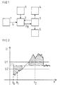
- FIG. 1 shows a block diagram of a device to determine the condition of a vehicle battery.
- the Figure 2 shows a sketch to illustrate the mode of operation a device according to a first embodiment for the invention.
- Figure 3 shows one Sketch to illustrate how a Device according to a second embodiment for The invention.
- Figure 4 shows a sketch for illustration the mode of operation of a device a third embodiment for the invention.
- FIG. 1 shows a block diagram of a device for determining the state of a vehicle battery.
- This device has a voltmeter 1, which is provided for measuring the battery voltage.
- the output signals of the voltmeter 1 are fed to an evaluation unit 2 which, using the signals supplied to it by the voltmeter 1 and preferably using further signals at its output, provides a signal U B which describes the state of the vehicle battery.
- the further signals mentioned are also referred to below as status information.
- the signal U B is fed to the energy management 3 of the vehicle. Energy management 3 is intended to influence the energy supply and energy consumption available in the vehicle.
- the energy manager 3 initiates suitable countermeasures to improve the charge balance of the vehicle battery in order to ensure that the safety-relevant components of the vehicle continue to work.
- These safety-relevant components include, for example, an electro-hydraulic brake and the power steering of the vehicle.
- the suitable countermeasures are that the energy management 3 closes a switch 4 in order to connect an auxiliary battery. Additionally or alternatively, the energy management 3 also provides a further switching unit 5 with control signals by means of which, for the purpose of reducing the energy consumption, consumers of the vehicle which are not safety-relevant are switched off or at least their power consumption is reduced.
- non-safety-relevant consumers include, for example, the rear window heating of the vehicle and the seat heating.
- the further signals which the evaluation unit 2 preferably uses to determine the signal U B describing the state of the vehicle battery are made available to the evaluation unit 2, for example by an information transmitter 6 and / or the energy management 3. This is additional information available from the vehicle electrical system. This further information includes information about the temperature of the battery, information about the energy status of the vehicle, information about load jumps occurring in the vehicle electrical system, information about voltage dips that occur, information about the battery current and information about the quiescent voltage.
- the information mentioned is sent to the evaluation unit 2 via the vehicle's CAN bus. They can also be fed to the evaluation unit 2 directly from the respective information source or via other bus configurations.
- FIG. 2 shows a sketch to illustrate the functioning of a device according to a first exemplary embodiment of the invention.
- the battery voltage U measured by the voltmeter 1 is fed to the evaluation unit 2.
- the evaluation unit 2 has an integrator. This is started after every vehicle start, after an initialization has been carried out and a battery idle current evaluation has taken place. It calculates a voltage integral L (t), which provides information about the charge balance of the vehicle battery, according to the following relationship:
- U1 is a predetermined upper voltage threshold
- U2 a predetermined lower voltage threshold. This Voltage thresholds are dependent on the given application.
- the weighting factor a [U ( ⁇ )] has for measured voltage values, those below the lower voltage threshold U2, the value 1.
- the weighting factor a [U ( ⁇ )] has for measured voltage values, those above the upper voltage threshold U1, the value 1.
- the voltage integral L determined is compared in the evaluation unit 2 with a predetermined limit value G. If the determined voltage integral L falls below this limit value, then the evaluation unit 2 generates a state of charge signal U B , which signals the energy management 3 that the state of charge of the vehicle battery is insufficient. The energy management 3 then initiates measures to improve the charge balance. For example, a switch 4 is closed in order to connect an auxiliary battery. As an alternative or in addition to this, the energy management 3 can also generate control signals for the switching unit 5, as a result of which non-safety-relevant consumers of the vehicle are switched off or their power consumption is reduced.
- the auxiliary battery then remains switched off and the non-security consumers remain - if they are currently activated - in operation.
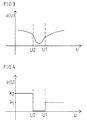
- FIG. 3 shows a sketch to illustrate the functioning of a device according to a second exemplary embodiment of the invention.
- the weighting factor a in this second exemplary embodiment also includes the dependence of the battery current on the current voltage. Consequently, in contrast to the first exemplary embodiment, the weighting factor a is no longer constant in sections, but has, for example, a profile as shown in FIG. 3.
- the information U B ascertained about the state of charge of the vehicle battery in energy management 3 is converted into control signals for switch 4 and / or switching unit 5.
- FIG. 4 shows a sketch to illustrate the Operation of a device according to a third embodiment for the invention.
- the variable is calibrated Weighting factor a by determining the state of charge using a quiescent voltage measurement.
- shape parameters that are included in the weighting factor come in, using correction data, which are obtained after a vehicle start, dynamic customized. This results in using that an integrated charge balance determination with time in the sense of self-adaptation always improved.
- a (U) a (k 1 , k 2 , ..., k n ; U).
- the weighting factor a is therefore dependent on the measured voltage U and a large number of preliminary factors k 1 , k 2 , ..., k n .
- FIG. 4 shows a simple exemplary embodiment, in which it is assumed that only two weight functions a 1 (U) and a 2 (U) are included in the calculation of the weighting factor, each of these weight functions being assigned a pre-factor k 1 and k 2 , respectively is.
- a (U) k 1 • a 1 (U) + k 2 • a 2 (U).
- any pre-factors k i can be used for the different weight functions in this exemplary embodiment.
- These pre-factors are variable and can be obtained through calibration and other available information such as status information from electrical energy management, information about load jumps and information about voltage dips in the vehicle electrical system. In practice, it makes sense to limit yourself to two or three weight functions and the associated pre-factors, depending on the application at hand.
- US, U1 and U2 are suitable voltage threshold values.
- the present invention is a Procedure that is easy and inexpensive to implement to determine the condition of a vehicle battery and the vehicle electrical system status is also available posed.
- the battery voltage is measured and fed to an evaluation unit. This is done an integration process in which a variable weighting factor is taken into account.
- the weighting factor can only depend on the measured battery voltage or also depending on other sizes his.
Landscapes
- Physics & Mathematics (AREA)
- General Physics & Mathematics (AREA)
- Secondary Cells (AREA)
- Electric Propulsion And Braking For Vehicles (AREA)
- Charge And Discharge Circuits For Batteries Or The Like (AREA)
- Tests Of Electric Status Of Batteries (AREA)
Applications Claiming Priority (2)
| Application Number | Priority Date | Filing Date | Title |
|---|---|---|---|
| DE10301529A DE10301529A1 (de) | 2003-01-17 | 2003-01-17 | Verfahren und Vorrichtung zur Ermittlung des Zustands einer Fahrzeugbatterie |
| DE10301529 | 2003-01-17 |
Publications (2)
| Publication Number | Publication Date |
|---|---|
| EP1439399A2 true EP1439399A2 (fr) | 2004-07-21 |
| EP1439399A3 EP1439399A3 (fr) | 2005-12-07 |
Family
ID=32520007
Family Applications (1)
| Application Number | Title | Priority Date | Filing Date |
|---|---|---|---|
| EP03025647A Withdrawn EP1439399A3 (fr) | 2003-01-17 | 2003-11-07 | Procédé et appareil de détermination de la condition d'une batterie de véhicule |
Country Status (3)
| Country | Link |
|---|---|
| US (1) | US7193421B2 (fr) |
| EP (1) | EP1439399A3 (fr) |
| DE (1) | DE10301529A1 (fr) |
Cited By (1)
| Publication number | Priority date | Publication date | Assignee | Title |
|---|---|---|---|---|
| DE102012212869B4 (de) | 2011-07-26 | 2021-08-12 | GM Global Technology Operations LLC (n. d. Gesetzen des Staates Delaware) | Verfahren und System zum Steuern einer Fahrzeugbatterie |
Families Citing this family (1)
| Publication number | Priority date | Publication date | Assignee | Title |
|---|---|---|---|---|
| TWI522789B (zh) * | 2014-08-29 | 2016-02-21 | 宏碁股份有限公司 | 電子裝置以及電量偵測方法 |
Family Cites Families (6)
| Publication number | Priority date | Publication date | Assignee | Title |
|---|---|---|---|---|
| US4388618A (en) * | 1981-01-07 | 1983-06-14 | Curtis Instruments, Inc. | Battery state of charge indicator operating on bidirectional integrations of terminal voltage |
| DE19845562C1 (de) * | 1998-10-02 | 2000-04-20 | Volkswagen Ag | Verfahren und Vorrichtung zur Ermittlung des Bordnetzzustands eines Kraftfahrzeugs |
| US6646561B1 (en) * | 2000-10-06 | 2003-11-11 | Battery Alert Ltd. | Method and device for in-use detecting low cranking strength of a combustion engine battery during engine starting |
| US6359419B1 (en) * | 2000-12-27 | 2002-03-19 | General Motors Corporation | Quasi-adaptive method for determining a battery's state of charge |
| US6356083B1 (en) * | 2001-02-07 | 2002-03-12 | General Motors Corporation | State of charge algorithm for a battery |
| JP4786058B2 (ja) * | 2001-05-01 | 2011-10-05 | 本田技研工業株式会社 | 蓄電装置の残容量検出装置 |
-
2003
- 2003-01-17 DE DE10301529A patent/DE10301529A1/de not_active Ceased
- 2003-11-07 EP EP03025647A patent/EP1439399A3/fr not_active Withdrawn
-
2004
- 2004-01-20 US US10/760,978 patent/US7193421B2/en not_active Expired - Fee Related
Cited By (1)
| Publication number | Priority date | Publication date | Assignee | Title |
|---|---|---|---|---|
| DE102012212869B4 (de) | 2011-07-26 | 2021-08-12 | GM Global Technology Operations LLC (n. d. Gesetzen des Staates Delaware) | Verfahren und System zum Steuern einer Fahrzeugbatterie |
Also Published As
| Publication number | Publication date |
|---|---|
| DE10301529A1 (de) | 2004-07-29 |
| US7193421B2 (en) | 2007-03-20 |
| US20040189310A1 (en) | 2004-09-30 |
| EP1439399A3 (fr) | 2005-12-07 |
Similar Documents
| Publication | Publication Date | Title |
|---|---|---|
| DE102006018208B4 (de) | Verfahren und Vorrichtung zum Detektieren eines geladenen Zustandes einer sekundären Batterie basierend auf einer Berechnung eines neuronalen Netzwerks | |
| DE4418194C2 (de) | System und Verfahren zum Bestimmen der Restkapazität einer Batterie | |
| DE69909472T2 (de) | Vorrichtung zum schätzen des ladungszustands einer batterie und verfahren zum schätzen des abnutzungszustands einer batterie | |
| EP3126181B1 (fr) | Procédé de contrôle d'une connexion entre un réseau basse tension et une batterie, et véhicule automobile | |
| DE10246383B4 (de) | Verfahren und Einrichtung zum Berechnen des Ladewirkungsgrads und der elektrischen Ladungsmenge einer Batterie | |
| EP1391742B1 (fr) | Dispositif de surveillance et procédé de détermination de l'état de fonctionnement d'une batterie d'accumulateurs | |
| EP2893365A1 (fr) | Procédé et circuit permettant de contrôler la plausibilité d'un résultat de mesure de capteur de courant | |
| DE102019218591A1 (de) | Verfahren zur Abschätzung des Zustands eines Energiespeichers | |
| DE19709234C2 (de) | Verfahren und Vorrichtung zur Durchführung einer Diagnose bei einem Elektrolytkondensator im Betrieb | |
| DE102005026077A1 (de) | Verfahren und Vorrichtung zum Bestimmen des Ladungs- und/oder Alterungszustands eines Energiespeichers | |
| DE102018123552A1 (de) | Vorrichtung und verfahren zum aufwecken einer fahrzeugbatterie | |
| WO2019072488A1 (fr) | Dispositif de stockage d'énergie et système et procédé pour déterminer une capacité d'un dispositif de stockage d'énergie | |
| DE102012224112A1 (de) | Verfahren zum Einrichten eines Stromsensors | |
| DE19740535A1 (de) | Batterieladegerät, welches verschiedene Batterien mit unterschiedlichen Anzahlen an Zellen laden kann | |
| EP2318853A1 (fr) | Procédé de calcul de l'état de charge d'une batterie | |
| DE10001340B4 (de) | Verfahren zur Meßfehlerkompensation bei der Stromerfassung in einem Energiespeicher | |
| EP1439399A2 (fr) | Procédé et appareil de détermination de la condition d'une batterie de véhicule | |
| WO2009004007A1 (fr) | Procédé de détermination d'une variable d'état d'une batterie d'automobile permettant d'établir une corrélation avec l'état de charge de la batterie | |
| DE102007031304B4 (de) | Verfahren zur Ermittlung der Ruhespannung einer Kraftfahrzeugbatterie | |
| EP1423717B1 (fr) | Procede et dispositif pour realiser a bord un diagnostic d'un reseau de bord d'une automobile | |
| DE10328055A1 (de) | Zustandsgrößen- und Parameterschätzer mit mehreren Teilmodellen für einen elektrischen Energiespeicher | |
| WO2024037915A1 (fr) | Procédé de surveillance d'éléments de batterie d'une batterie d'un véhicule à moteur, programme informatique, dispositif de traitement de données et véhicule à moteur | |
| EP0992801B1 (fr) | Procédé et appareil pour déterminer l'état d'un réseau de bord dans un vehicule automobile | |
| DE19845562C1 (de) | Verfahren und Vorrichtung zur Ermittlung des Bordnetzzustands eines Kraftfahrzeugs | |
| DE102014200669A1 (de) | Verfahren zum Bestimmen von Größen für Batteriemanagementfunktionen |
Legal Events
| Date | Code | Title | Description |
|---|---|---|---|
| PUAI | Public reference made under article 153(3) epc to a published international application that has entered the european phase |
Free format text: ORIGINAL CODE: 0009012 |
|
| AK | Designated contracting states |
Kind code of ref document: A2 Designated state(s): AT BE BG CH CY CZ DE DK EE ES FI FR GB GR HU IE IT LI LU MC NL PT RO SE SI SK TR |
|
| AX | Request for extension of the european patent |
Extension state: AL LT LV MK |
|
| PUAL | Search report despatched |
Free format text: ORIGINAL CODE: 0009013 |
|
| AK | Designated contracting states |
Kind code of ref document: A3 Designated state(s): AT BE BG CH CY CZ DE DK EE ES FI FR GB GR HU IE IT LI LU MC NL PT RO SE SI SK TR |
|
| AX | Request for extension of the european patent |
Extension state: AL LT LV MK |
|
| 17P | Request for examination filed |
Effective date: 20060607 |
|
| AKX | Designation fees paid |
Designated state(s): DE ES FR IT |
|
| 17Q | First examination report despatched |
Effective date: 20110111 |
|
| STAA | Information on the status of an ep patent application or granted ep patent |
Free format text: STATUS: THE APPLICATION IS DEEMED TO BE WITHDRAWN |
|
| 18D | Application deemed to be withdrawn |
Effective date: 20110524 |