EP1439882B1 - Stimulation sequentielle atrio-ventriculaire permanente - Google Patents
Stimulation sequentielle atrio-ventriculaire permanente Download PDFInfo
- Publication number
- EP1439882B1 EP1439882B1 EP02776087A EP02776087A EP1439882B1 EP 1439882 B1 EP1439882 B1 EP 1439882B1 EP 02776087 A EP02776087 A EP 02776087A EP 02776087 A EP02776087 A EP 02776087A EP 1439882 B1 EP1439882 B1 EP 1439882B1
- Authority
- EP
- European Patent Office
- Prior art keywords
- bundle
- pacing
- atrial
- ventricular
- ventricles
- Prior art date
- Legal status (The legal status is an assumption and is not a legal conclusion. Google has not performed a legal analysis and makes no representation as to the accuracy of the status listed.)
- Expired - Lifetime
Links
Images
Classifications
-
- A—HUMAN NECESSITIES
- A61—MEDICAL OR VETERINARY SCIENCE; HYGIENE
- A61N—ELECTROTHERAPY; MAGNETOTHERAPY; RADIATION THERAPY; ULTRASOUND THERAPY
- A61N1/00—Electrotherapy; Circuits therefor
- A61N1/18—Applying electric currents by contact electrodes
- A61N1/32—Applying electric currents by contact electrodes alternating or intermittent currents
- A61N1/36—Applying electric currents by contact electrodes alternating or intermittent currents for stimulation
- A61N1/362—Heart stimulators
- A61N1/3627—Heart stimulators for treating a mechanical deficiency of the heart, e.g. congestive heart failure or cardiomyopathy
-
- A—HUMAN NECESSITIES
- A61—MEDICAL OR VETERINARY SCIENCE; HYGIENE
- A61N—ELECTROTHERAPY; MAGNETOTHERAPY; RADIATION THERAPY; ULTRASOUND THERAPY
- A61N1/00—Electrotherapy; Circuits therefor
- A61N1/18—Applying electric currents by contact electrodes
- A61N1/32—Applying electric currents by contact electrodes alternating or intermittent currents
- A61N1/36—Applying electric currents by contact electrodes alternating or intermittent currents for stimulation
- A61N1/362—Heart stimulators
- A61N1/365—Heart stimulators controlled by a physiological parameter, e.g. heart potential
- A61N1/368—Heart stimulators controlled by a physiological parameter, e.g. heart potential comprising more than one electrode co-operating with different heart regions
Definitions
- the present invention relates to an apparatus for cardiac pacing and, more particularly, for Atrial-His-Ventricular sequential pacing to improve sinoatrial node dysfunction or heart block superior to the His bundle.
- His- Ventricular sequential pacing can be employed to treat permanent atrial fibrillation.
- the sinoatrial (SA) node represents the natural pacemaker that controls the rhythmic electrical excitation in a normal human heart.
- SA node an electrical impulse arising from the SA node is transmitted to the right and left atrial chambers. This impulse causes muscle tissue surrounding the atrium to depolarize and contract which generates an electrical signal known as a P-wave.
- the same electrical impulse arising from the SA node also travels to the right and left ventricles through the atrioventricular (AV) node and atrioventricular (AV) bundle.
- AV node situated in the lower portion of the right atrium, receives the impulse to contract.
- the impulse is then transmitted through the AV bundle comprising Common Bundle of His (His bundle), right and left bundle branches, and Purkinje fibers that cover most of the endocardial surface of the ventricles.
- His bundle Common Bundle of His
- RV bundle right and left bundle branches
- Purkinje fibers that cover most of the endocardial surface of the ventricles.
- the ventricular muscle tissue depolarizes, generating an R-wave, then contracts. This forces blood held in the ventricles through the arteries and to various body locations. This action is repeated in a rhythmic cycle in which the atrial and ventricular chambers alternately contract and pump, then relax and fill.
- An artificial pacemaker is an implantable medical device that monitors the activity of the heart for the occurrence ofP- and/or R-waves. When a P- or R wave is not sensed after a prescribed period of time, the pacemaker electronically generates stimuli in order to force the depolarization of the atria and/or ventricles.
- a pacemaker-generated stimulus that is delivered to the atria is known as an A pulse, whereas a stimulus delivered to the ventricles is a V-pulse.
- pacing leads connected to an electrode are typically implanted in the apex of the right ventricle to deliver electrical impulses to the ventricular muscle tissue.
- this type of pacing results in the loss of synchronous mechanical contraction of the right and left ventricles due to the interventricular delay in impulse propagation to the left ventricle. This results in an immediate decrease in cardiac output along with potential deterioration of ventricular function over the long term as permanent changes occur in myocardial perfusion and structure.
- a method to pace both ventricles, bi-ventricular pacing has been demonstrated to restore substantially simultaneous contraction of both ventricles and is accomplished by placing one pacing lead in the apex of the right ventricle and another pacing lead through the coronary sinus into a vein on the left ventricular wall.
- the surgical procedure used to implant the pacing lead in the coronary sinus may be complex and a long pacing lead is needed to connect the electrode to the pulse generator thus requiring a higher voltage resulting in a large drain on the power source generating the pulses.
- DDD/R dual chamber pacing
- electrodes connected to pacing leads are placed in the atria (for example the right atrium) and one or both of the ventricles.
- AV delay optimal delay between the A pulse and V pulse
- the present invention is directed to a pacing apparatus for sequentially pacing the atria, His bundle and ventricles to provide synchronous mechanical contractions to improve cardiac output and prevent long term hemodynamic effects caused by unnecessary ventricular pacing.
- the invention provides a pacemaker configured to by-pass sino-atrial node dysfunction or heart block superior to the His bundle comprising:
- the electrical pulses travel through the right and left bundle branches and to the Purkinje fibers causing the ventricles to depolarize and contract
- the ventricles contract in a more coordinated manner as compared to ventricular pacing thus improving cardiac output and performance.
- the pacing apparatus is provided for patients who suffer from sino-atrial (SA) node dysfunction or heart block superior to the His bundle. Because these patients typically have normal ventricular contraction, continuously pacing the His bundle results in electrical pulses being sent from the atria to the ventricles to travel more quickly thus allowing the ventricular pacing lead to remain dormant during the pacing cycle.
- the ventricular pacing is provided only for emergency situations such as, for example, inter alia, if the His bundle pacing lead should fail or if heart block inferior to the His bundle should occur.
- the pacing apparatus is provided for patients who suffer from permanent atrial fibrillation.
- the His bundle pacing lead is implanted following AV node ablation to provide electrical pulses to the ventricles causing depolarization and contraction.
- a ventricular pacing lead is provided but remains dormant and is activated only in emergency situations.
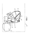
- the pacing system 10 comprises an implantable pacemaker (pacer) 11, from which three leads, 12A (trial), 12H (AV bundle) and 12V (ventricle) extend. It is recognized that actual lead packaging may vary, but at least three functional conductive leads must originate in pacer 11 to direct energy to various locations in the cardiac tissue.
- the pacing leads 12A, 12H and 12V enter the heart through the superior vena cava 13. Each pacing lead provides electrodes at or proximate to their distal ends for pacing and sensing electrical stimuli.
- Pacing lead 12A is anchored or otherwise positioned generally in the right atrium just below the SA node 14 for contacting the right atrium.
- Pacing lead 12H is positioned distal to the blocked or slowly conducting AV node and in the AV septum 15 for contacting the AV bundle comprising His bundle 16, right and left bundle branches 17, and the Purkinje fibers 18.
- the His bundle 16 is a structure of cardiac muscle through which all impulses from the atria are conducted to the ventricles of the heart.
- Pacing lead 12V is positioned so that its distal end is anchored in the apex of the right ventricle 19. The electrodes are stabilized or fixed in their respective positions in a manner well known in the art.
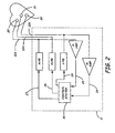
- pacer 11 a block diagram of pacer 11 is illustrated.
- the pacer is adapted to interface with the atria, His bundle and ventricles of the heart Those portions of pacer 11 that interface with the atria, His bundle and ventricles, and the corresponding portions of control system 35 are commonly referred to as the atrial, His bundle and ventricular channels, respectively.
- Pacer 11 generates electrical pulses that are transmitted through pacing leads 12A, 12H and 12V.
- Control system 35 controls pacer 11.
- the control system includes timing circuitry and a microprocessor for carrying out logical steps in analyzing received signals, and determining when pace pulses should be initiated, with particular sequences and locations comprising part of the present invention.
- the leads 12A, 12H, and 12V carry the stimulating pulses to electrodes 20, 21 and 22 from an atrial pulse generator A-PG , His bundle pulse generator H-PG and a ventricular pulse generator V-PG 27, respectively.
- An electrical pulse generated by A-PG is known as an A-pulse; an electrical pulse generated by H-PG is known as an H-pulse; and an electrical pulse generated by V-PG is known as a V-pulse.
- natural electrical signals from the atria are carried from the electrode 20, through lead 12A, to the input channel of an atrial channel sense amplifier P-AMP.
- natural electrical signals from the ventricles are carried from electrode 22, through the lead 12V, to the input terminal of a ventricular sense channel amplifier R-AMP.
- P-waves natural electrical signals from the atria
- R-waves natural electrical signals from the ventricles
- the control system 35 receives the output signals from P-AMP over signal line 25.
- the control system 35 also receives the output signals from R-AMP over signal line 26.
- the control system 35 also generates trigger signals when needed that are sent to A-PG, H-PG and V-PG over signal lines 27, 28 and 29 respectively. These trigger signals are generated each time that an electrical pulse is to be generated by the respective pulse generator.
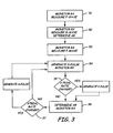
- FIG. 3 there is shown a logic control flow diagram for controlling the system of this invention to pace a patient with SA node dysfunction or AV conduction block superior to the His bundle.
- the assumption is that the right and left ventricles are functioning normally but that sinus signals from the SA node to the AV Bundle are not occurring or are being delayed from the atria to the ventricles within the AV node.
- the pacer monitors the right atrium and measures a P-wave generated by the SA node.
- the pacer transmits an H-pulse through the pacing lead to an electrode located distal to the AV node to stimulate the His bundle.
- the H-pulse is transmitted through the His bundle to the right and left bundle branches of the heart and then to the Purkinje fibers to cause ventricular depolarization. Then, the pacer senses the right ventricle for an R-wave. As shown in 55, if an R-wave is not sensed following atrial activity plus some predescribed period of time, the right ventricle is electrically paced with a V-pulse generated by the pacer. In 56, a subsequent P-wave is sensed in the right atrium. As shown in 57, if a P-wave is not sensed following ventricular activity plus some prescribed period of time, the pacer generates an electrical stimulus, or A-pulse, to the right atrium.
- An H-pulse is generated immediately following atrial activity and sent to the electrode located near the AV bundle and the right ventricle is again monitored for ventricular depolarization as the cardiac cycle continues.
- the advantage to this system is that both the atrial and ventricular pacing leads remain dormant throughout the cardiac cycle unless a P-wave or R-wave is not sensed within a prescribed period of time. This eliminates the harmful hemodynamic effects suffered by patients who are currently unnecessarily ventricularly paced.
- the His-bundle, right and left bundle branches and Purkinje fibers as a pacing pathway generates a more natural synchronous mechanical ventricular contraction to improve cardiac output
- the pacer measures a P-wave generated by the SA node.
- an electrode is placed distal to the AV node to stimulate the His bundle.
- the pacer sends an H-pulse to this electrode immediately following the sensing of a P-wave.
- the ventricular pacing lead remains dormant throughout this cycle unless an R-wave is not sensed following atrial activity plus a prescribed period of time, after which the pacer would generate a V-pulse to force the ventricles to contract.
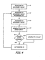
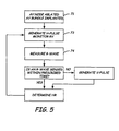
- FIG. 5 there is shown a logic control flow diagram for controlling the system of this invention to pace a patient with permanent atrial fibrillation. It's assumed that the patient suffers from a fast and unreliable ventricular response. According to current practice, these patients are treated by ablating the AV node and placing a permanent single-chamber pacemaker with the lead tip in the right ventricle to restore normal ventricular rhythm. However, this can cause hemodynamic deterioration and death in some patients. In order to provide these patients with improved long-term pacing, AV node ablation can be followed by permanent His bundle pacing. As shown in 71, AV node ablation is preceded by implanting a pacemaker distal to the AV node to stimulate the His bundle.
- Continuous H-pulses are transmitted to the His bundle via the electrode located at the AV bundle, to cause the ventricles to depolarize as shown in 73 and 74.
- a second pacing lead is anchored in the apex of the right ventricle to provide V-pulses when necessary.
- a V-pulse is generated by the pacer and transmitted to the right ventricle causing the ventricles to contract.
- the subsequent H-pulse is generated according to the operating pacing rate to continue the cardiac cycle.
- a V-pulse is generated only on an emergency basis, i.e. when heart block occurs inferior to the His bundle.
Landscapes
- Health & Medical Sciences (AREA)
- Cardiology (AREA)
- Hospice & Palliative Care (AREA)
- Heart & Thoracic Surgery (AREA)
- Engineering & Computer Science (AREA)
- Biomedical Technology (AREA)
- Nuclear Medicine, Radiotherapy & Molecular Imaging (AREA)
- Radiology & Medical Imaging (AREA)
- Life Sciences & Earth Sciences (AREA)
- Animal Behavior & Ethology (AREA)
- General Health & Medical Sciences (AREA)
- Public Health (AREA)
- Veterinary Medicine (AREA)
- Electrotherapy Devices (AREA)
Claims (2)
- Stimulateur cardiaque configuré pour éviter un dysfonctionnement d'un noeud sino-auriculaire ou un bloc cardiaque supérieur au faisceau de His (16) comportant :(a) une électrode auriculaire (20) détectant une activité électrique auriculaire ; et(b) une électrode de stimulation de faisceau de His (21) en contact avec le faisceau de His ; caractérisé par(c) une électrode de détection et de stimulation ventriculaire (22) en contact avec l'un des ventricules du coeur ; et(d) un générateur d'impulsions pour traiter une activité électrique détectée et générer des impulsions de stimulation de His (impulsion H) en commençant immédiatement après la détection de l'activité électrique auriculaire pour engendrer une dépolarisation ventriculaire ; après quoi une impulsion V est générée par le générateur d'impulsions et appliquée à l'un des ventricules du coeur si la dépolarisation ventriculaire n'est pas détectée par l'électrode ventriculaire au cours d'une durée prescrite de ladite activité auriculaire.
- Stimulateur cardiaque selon la revendication 1, dans lequel l'électrode auriculaire (20) est en outre adaptée pour stimuler l'oreillette droite et le générateur d'impulsions est en outre adapté pour générer l'activité électrique auriculaire via l'électrode auriculaire.
Applications Claiming Priority (3)
| Application Number | Priority Date | Filing Date | Title |
|---|---|---|---|
| US47632 | 1998-03-25 | ||
| US10/047,632 US6718206B2 (en) | 2001-10-23 | 2001-10-23 | Permanent atrial-his-ventricular sequential pacing |
| PCT/US2002/031390 WO2003035170A1 (fr) | 2001-10-23 | 2002-10-01 | Stimulation sequentielle atrio-ventriculaire permanente |
Publications (2)
| Publication Number | Publication Date |
|---|---|
| EP1439882A1 EP1439882A1 (fr) | 2004-07-28 |
| EP1439882B1 true EP1439882B1 (fr) | 2008-08-06 |
Family
ID=21950041
Family Applications (1)
| Application Number | Title | Priority Date | Filing Date |
|---|---|---|---|
| EP02776087A Expired - Lifetime EP1439882B1 (fr) | 2001-10-23 | 2002-10-01 | Stimulation sequentielle atrio-ventriculaire permanente |
Country Status (6)
| Country | Link |
|---|---|
| US (1) | US6718206B2 (fr) |
| EP (1) | EP1439882B1 (fr) |
| JP (1) | JP2005506884A (fr) |
| CA (1) | CA2462964A1 (fr) |
| DE (1) | DE60228112D1 (fr) |
| WO (1) | WO2003035170A1 (fr) |
Families Citing this family (50)
| Publication number | Priority date | Publication date | Assignee | Title |
|---|---|---|---|---|
| KR101085372B1 (ko) * | 2002-12-10 | 2011-11-21 | 가부시키가이샤 니콘 | 노광 장치 및 디바이스 제조 방법 |
| US7738954B1 (en) * | 2004-04-22 | 2010-06-15 | Pacesetter, Inc. | His bundle control |
| FR2873930B1 (fr) * | 2004-08-04 | 2006-09-29 | Ela Medical Sa | Dispositif medical implantable actif comprenant un mode de resynchronisation des contractions ventriculaires pour le traitement de l'insuffisance cardiaque |
| AR047851A1 (es) | 2004-12-20 | 2006-03-01 | Giniger Alberto German | Un nuevo marcapasos que restablece o preserva la conduccion electrica fisiologica del corazon y un metodo de aplicacion |
| US8010191B2 (en) | 2004-12-20 | 2011-08-30 | Cardiac Pacemakers, Inc. | Systems, devices and methods for monitoring efficiency of pacing |
| US8050756B2 (en) | 2004-12-20 | 2011-11-01 | Cardiac Pacemakers, Inc. | Circuit-based devices and methods for pulse control of endocardial pacing in cardiac rhythm management |
| US8290586B2 (en) | 2004-12-20 | 2012-10-16 | Cardiac Pacemakers, Inc. | Methods, devices and systems for single-chamber pacing using a dual-chamber pacing device |
| US8005544B2 (en) | 2004-12-20 | 2011-08-23 | Cardiac Pacemakers, Inc. | Endocardial pacing devices and methods useful for resynchronization and defibrillation |
| US8326423B2 (en) | 2004-12-20 | 2012-12-04 | Cardiac Pacemakers, Inc. | Devices and methods for steering electrical stimulation in cardiac rhythm management |
| US8423139B2 (en) | 2004-12-20 | 2013-04-16 | Cardiac Pacemakers, Inc. | Methods, devices and systems for cardiac rhythm management using an electrode arrangement |
| US8014861B2 (en) | 2004-12-20 | 2011-09-06 | Cardiac Pacemakers, Inc. | Systems, devices and methods relating to endocardial pacing for resynchronization |
| US8010192B2 (en) * | 2004-12-20 | 2011-08-30 | Cardiac Pacemakers, Inc. | Endocardial pacing relating to conduction abnormalities |
| US7460902B2 (en) * | 2005-02-02 | 2008-12-02 | The General Electric Company | Monitoring of atrial activation |
| US8565898B2 (en) * | 2005-04-28 | 2013-10-22 | Medtronic, Inc. | Rate control during AF using cellular intervention to modulate AV node |
| US8560068B2 (en) * | 2007-12-18 | 2013-10-15 | St. Jude Medical Ab | Medical device for stimulation of the HIS bundle |
| US8986253B2 (en) | 2008-01-25 | 2015-03-24 | Tandem Diabetes Care, Inc. | Two chamber pumps and related methods |
| US8874237B2 (en) | 2008-04-16 | 2014-10-28 | Medtronic, Inc. | Delivery catheter including side port and electrodes |
| US8408421B2 (en) | 2008-09-16 | 2013-04-02 | Tandem Diabetes Care, Inc. | Flow regulating stopcocks and related methods |
| EP2334234A4 (fr) | 2008-09-19 | 2013-03-20 | Tandem Diabetes Care Inc | Dispositif de mesure de la concentration d'un soluté et procédés associés |
| US10695126B2 (en) | 2008-10-06 | 2020-06-30 | Santa Anna Tech Llc | Catheter with a double balloon structure to generate and apply a heated ablative zone to tissue |
| AU2009327369B2 (en) | 2008-12-19 | 2012-10-11 | Cardiac Pacemakers, Inc. | Devices, methods, and systems including cardiac pacing |
| US8125058B2 (en) * | 2009-06-10 | 2012-02-28 | Medtronic, Inc. | Faraday cage for circuitry using substrates |
| US8172760B2 (en) | 2009-06-18 | 2012-05-08 | Medtronic, Inc. | Medical device encapsulated within bonded dies |
| US8758323B2 (en) | 2009-07-30 | 2014-06-24 | Tandem Diabetes Care, Inc. | Infusion pump system with disposable cartridge having pressure venting and pressure feedback |
| US20110230922A1 (en) * | 2010-03-17 | 2011-09-22 | Fishel Robert S | Device And Method For Peri-Hisian Pacing And/Or Simultaneous Bi-Ventricular or Tri-Ventricular Pacing For Cardiac Resynchronization |
| US8565880B2 (en) | 2010-04-27 | 2013-10-22 | Cardiac Pacemakers, Inc. | His-bundle capture verification and monitoring |
| EP2629843A1 (fr) * | 2010-10-22 | 2013-08-28 | Cardiac Pacemakers, Inc. | Appareil de synchronisation pour la stimulation du faisceau de his |
| US8666505B2 (en) | 2010-10-26 | 2014-03-04 | Medtronic, Inc. | Wafer-scale package including power source |
| US8424388B2 (en) | 2011-01-28 | 2013-04-23 | Medtronic, Inc. | Implantable capacitive pressure sensor apparatus and methods regarding same |
| US8761880B2 (en) | 2011-03-14 | 2014-06-24 | Cardiac Pacemakers, Inc. | His capture verification using electro-mechanical delay |
| US9180242B2 (en) | 2012-05-17 | 2015-11-10 | Tandem Diabetes Care, Inc. | Methods and devices for multiple fluid transfer |
| EP2719425B1 (fr) * | 2012-10-12 | 2015-04-08 | Sorin CRM SAS | Sonde de stimulation cardiaque implantable le long de la paroi du septum interventriculaire et/ou de la paroi libre du ventricule gauche |
| US9173998B2 (en) | 2013-03-14 | 2015-11-03 | Tandem Diabetes Care, Inc. | System and method for detecting occlusions in an infusion pump |
| US12364537B2 (en) | 2016-05-02 | 2025-07-22 | Santa Anna Tech Llc | Catheter with a double balloon structure to generate and apply a heated ablative zone to tissue |
| US11331140B2 (en) | 2016-05-19 | 2022-05-17 | Aqua Heart, Inc. | Heated vapor ablation systems and methods for treating cardiac conditions |
| WO2019079418A1 (fr) | 2017-10-17 | 2019-04-25 | Medtronic, Inc. | Dispositifs et procédés de stimulation de branche de faisceau |
| CN111295224B (zh) | 2017-11-02 | 2024-05-24 | 心脏起搏器股份公司 | 用于希氏束起搏的系统 |
| US10842999B2 (en) | 2018-03-22 | 2020-11-24 | Medtronic, Inc. | Monitoring of His Bundle pacing capture during ventricular pacing therapy |
| CN112543662B (zh) | 2018-07-06 | 2024-09-20 | 心脏起搏器股份公司 | 希氏束起搏器中的可调节感测 |
| US10729902B1 (en) | 2018-07-15 | 2020-08-04 | Eagle Point Medical LLC | Intraseptal multi-electrode cardiac pacemaker and methods of use thereof |
| US11000689B2 (en) | 2018-07-15 | 2021-05-11 | Eagle Point Medical LLC | Leadless multi-electrode cardiac pacemakers and methods of implantation thereof |
| US10406370B1 (en) | 2018-07-15 | 2019-09-10 | Eagle Point Medical LLC | Single conduit multi-electrode cardiac pacemaker and methods of using thereof |
| US10695558B2 (en) | 2018-07-15 | 2020-06-30 | Eagle Point Medical LLC | Single conduit multi-electrode cardiac pacemaker and methods of using thereof |
| US10850107B2 (en) | 2018-11-05 | 2020-12-01 | Pacesetter, Inc. | Automated optimization of his bundle pacing for cardiac resynchronization therapy |
| US11207523B2 (en) | 2018-12-10 | 2021-12-28 | Cardiac Pacemakers, Inc. | His-bundle pacing for rate regularization |
| US11679265B2 (en) | 2019-02-14 | 2023-06-20 | Medtronic, Inc. | Lead-in-lead systems and methods for cardiac therapy |
| US11779769B2 (en) | 2019-09-19 | 2023-10-10 | Pacesetter, Inc. | Method and device for avoiding atrial activity oversensing on his sensing channel |
| US11752347B2 (en) | 2020-07-31 | 2023-09-12 | Medtronic, Inc. | Cardiac conduction system pacing |
| US12186567B2 (en) | 2020-12-02 | 2025-01-07 | Cardiac Pacemakers, Inc. | Ventricular blanking period after atrially sensed beats |
| US12280260B2 (en) | 2020-12-02 | 2025-04-22 | Medtronic, Inc. | Evaluation and adjustment of left bundle branch (LBB) pacing therapy |
Family Cites Families (11)
| Publication number | Priority date | Publication date | Assignee | Title |
|---|---|---|---|---|
| US4354497A (en) | 1977-05-23 | 1982-10-19 | Medtronic, Inc. | Cardiac depolarization detection apparatus |
| US5320642A (en) | 1990-06-01 | 1994-06-14 | Board Of Regents For The University Of Ok | Method for alleviating and diagnosing symptoms of heart block |
| US5083564A (en) | 1990-06-01 | 1992-01-28 | Board Of Regents Of The University Of Oklahoma | Method for alleviating and diagnosing symptoms of heart block |
| US5174289A (en) | 1990-09-07 | 1992-12-29 | Cohen Fred M | Pacing systems and methods for control of the ventricular activation sequence |
| US5246014A (en) | 1991-11-08 | 1993-09-21 | Medtronic, Inc. | Implantable lead system |
| US5403356A (en) | 1993-04-28 | 1995-04-04 | Medtronic, Inc. | Method and apparatus for prevention of atrial tachy arrhythmias |
| SE9301628D0 (sv) | 1993-05-12 | 1993-05-12 | Siemens-Elema Ab | Foerfarande och anordning foer att bestaemma om elektriska signaler i ett hjaerta aer orsakade av en atriell depolarisation |
| US5514163A (en) | 1995-02-21 | 1996-05-07 | Medtronic, Inc. | Dual chamber pacing system and method with optimized adjustment of the AV escape interval for treating cardiomyopathy |
| US5643338A (en) | 1996-04-03 | 1997-07-01 | Pacesetter, Inc. | Single-pass A-V lead for pacing with stimulation of right ventricular outflow tract |
| US6493586B1 (en) | 2000-08-30 | 2002-12-10 | Cardiac Pacemakers, Inc. | Site reversion in cardiac rhythm management |
| US6609027B2 (en) | 2001-02-23 | 2003-08-19 | Pacesetter, Inc. | His Bundle sensing device and associated method |
-
2001
- 2001-10-23 US US10/047,632 patent/US6718206B2/en not_active Expired - Lifetime
-
2002
- 2002-10-01 DE DE60228112T patent/DE60228112D1/de not_active Expired - Lifetime
- 2002-10-01 WO PCT/US2002/031390 patent/WO2003035170A1/fr not_active Ceased
- 2002-10-01 JP JP2003537732A patent/JP2005506884A/ja active Pending
- 2002-10-01 EP EP02776087A patent/EP1439882B1/fr not_active Expired - Lifetime
- 2002-10-01 CA CA002462964A patent/CA2462964A1/fr not_active Abandoned
Also Published As
| Publication number | Publication date |
|---|---|
| CA2462964A1 (fr) | 2003-05-01 |
| DE60228112D1 (de) | 2008-09-18 |
| US20030078625A1 (en) | 2003-04-24 |
| US6718206B2 (en) | 2004-04-06 |
| JP2005506884A (ja) | 2005-03-10 |
| WO2003035170A1 (fr) | 2003-05-01 |
| EP1439882A1 (fr) | 2004-07-28 |
Similar Documents
| Publication | Publication Date | Title |
|---|---|---|
| US6718206B2 (en) | Permanent atrial-his-ventricular sequential pacing | |
| EP1272251B1 (fr) | Systeme de distribution spatiale et temporelle de stimulations cardiaques | |
| US6456878B1 (en) | Cardiac pacing system delivering multi-site pacing in a predetermined sequence triggered by a sense event | |
| US6292693B1 (en) | Contractility enhancement using excitable tissue control and multi-site pacing | |
| US6421564B1 (en) | Bi-chamber cardiac pacing system employing unipolar left heart chamber lead in combination with bipolar right chamber lead | |
| US6122545A (en) | Multiple channel sequential cardiac pacing method | |
| EP3326690B1 (fr) | Dispositif médical implantable bi-ventriculaire | |
| US6496730B1 (en) | Multi-site cardiac pacing system having conditional refractory period | |
| US5902324A (en) | Bi-atrial and/or bi-ventricular sequential cardiac pacing systems | |
| US6477415B1 (en) | AV synchronous cardiac pacing system delivering multi-site ventricular pacing triggered by a ventricular sense event during the AV delay | |
| US8750993B2 (en) | Multi-site pacing for atrial tachyarrhythmias | |
| CA2306708A1 (fr) | Stimulateur cardiaque implantable a detection d'onde t asservie a l'activite | |
| US9254391B2 (en) | Systems and methods for determining pacing related parameters | |
| EP2957321A1 (fr) | Appareil permettant d'optimiser des paramètres de stimulation | |
| US6324425B1 (en) | Recharge circuitry for multi-site stimulation of body tissue | |
| US7194307B2 (en) | Pacing method and device for preserving native conduction system | |
| US20070129762A1 (en) | Cardiac pacemaker with dynamic conduction time monitoring | |
| WO1998046304A1 (fr) | Periode de suppression auriculaire variable dans un dispositif medical implantable | |
| US20120239100A1 (en) | Atrial nerve stimulation with ventricular pacing | |
| CN101505828B (zh) | 用于治疗作用的间歇性高能心脏刺激 | |
| US7738954B1 (en) | His bundle control | |
| US20050055057A1 (en) | Method and apparatus for providing ipselateral therapy | |
| WO2012125222A1 (fr) | Stimulation du nerf atrial par stimulation ventriculaire |
Legal Events
| Date | Code | Title | Description |
|---|---|---|---|
| PUAI | Public reference made under article 153(3) epc to a published international application that has entered the european phase |
Free format text: ORIGINAL CODE: 0009012 |
|
| 17P | Request for examination filed |
Effective date: 20040512 |
|
| AK | Designated contracting states |
Kind code of ref document: A1 Designated state(s): AT BE BG CH CY CZ DE DK EE ES FI FR GB GR IE IT LI LU MC NL PT SE SK TR |
|
| AX | Request for extension of the european patent |
Extension state: AL LT LV MK RO SI |
|
| RAP1 | Party data changed (applicant data changed or rights of an application transferred) |
Owner name: MEDTRONIC, INC. |
|
| GRAP | Despatch of communication of intention to grant a patent |
Free format text: ORIGINAL CODE: EPIDOSNIGR1 |
|
| GRAS | Grant fee paid |
Free format text: ORIGINAL CODE: EPIDOSNIGR3 |
|
| GRAA | (expected) grant |
Free format text: ORIGINAL CODE: 0009210 |
|
| AK | Designated contracting states |
Kind code of ref document: B1 Designated state(s): CH DE FR LI NL SE |
|
| REG | Reference to a national code |
Ref country code: CH Ref legal event code: EP |
|
| REF | Corresponds to: |
Ref document number: 60228112 Country of ref document: DE Date of ref document: 20080918 Kind code of ref document: P |
|
| PG25 | Lapsed in a contracting state [announced via postgrant information from national office to epo] |
Ref country code: NL Free format text: LAPSE BECAUSE OF FAILURE TO SUBMIT A TRANSLATION OF THE DESCRIPTION OR TO PAY THE FEE WITHIN THE PRESCRIBED TIME-LIMIT Effective date: 20080806 |
|
| REG | Reference to a national code |
Ref country code: CH Ref legal event code: PL |
|
| PLBE | No opposition filed within time limit |
Free format text: ORIGINAL CODE: 0009261 |
|
| STAA | Information on the status of an ep patent application or granted ep patent |
Free format text: STATUS: NO OPPOSITION FILED WITHIN TIME LIMIT |
|
| 26N | No opposition filed |
Effective date: 20090507 |
|
| PG25 | Lapsed in a contracting state [announced via postgrant information from national office to epo] |
Ref country code: LI Free format text: LAPSE BECAUSE OF NON-PAYMENT OF DUE FEES Effective date: 20081031 Ref country code: CH Free format text: LAPSE BECAUSE OF NON-PAYMENT OF DUE FEES Effective date: 20081031 |
|
| PG25 | Lapsed in a contracting state [announced via postgrant information from national office to epo] |
Ref country code: SE Free format text: LAPSE BECAUSE OF FAILURE TO SUBMIT A TRANSLATION OF THE DESCRIPTION OR TO PAY THE FEE WITHIN THE PRESCRIBED TIME-LIMIT Effective date: 20081106 |
|
| PGFP | Annual fee paid to national office [announced via postgrant information from national office to epo] |
Ref country code: DE Payment date: 20131029 Year of fee payment: 12 Ref country code: FR Payment date: 20131017 Year of fee payment: 12 |
|
| REG | Reference to a national code |
Ref country code: DE Ref legal event code: R119 Ref document number: 60228112 Country of ref document: DE |
|
| PG25 | Lapsed in a contracting state [announced via postgrant information from national office to epo] |
Ref country code: DE Free format text: LAPSE BECAUSE OF NON-PAYMENT OF DUE FEES Effective date: 20150501 |
|
| REG | Reference to a national code |
Ref country code: FR Ref legal event code: ST Effective date: 20150630 |
|
| PG25 | Lapsed in a contracting state [announced via postgrant information from national office to epo] |
Ref country code: FR Free format text: LAPSE BECAUSE OF NON-PAYMENT OF DUE FEES Effective date: 20141031 |