EP1440211B1 - Arbeitsmaschine und verfahren zum betreiben einer arbeitsmaschine - Google Patents
Arbeitsmaschine und verfahren zum betreiben einer arbeitsmaschine Download PDFInfo
- Publication number
- EP1440211B1 EP1440211B1 EP02802301A EP02802301A EP1440211B1 EP 1440211 B1 EP1440211 B1 EP 1440211B1 EP 02802301 A EP02802301 A EP 02802301A EP 02802301 A EP02802301 A EP 02802301A EP 1440211 B1 EP1440211 B1 EP 1440211B1
- Authority
- EP
- European Patent Office
- Prior art keywords
- undercarriage
- electronics
- work machine
- machine according
- superstructure
- Prior art date
- Legal status (The legal status is an assumption and is not a legal conclusion. Google has not performed a legal analysis and makes no representation as to the accuracy of the status listed.)
- Expired - Lifetime
Links
- 238000000034 method Methods 0.000 title claims description 13
- 230000002706 hydrostatic effect Effects 0.000 claims abstract description 5
- 230000005540 biological transmission Effects 0.000 claims description 16
- 238000004891 communication Methods 0.000 claims description 10
- 230000001419 dependent effect Effects 0.000 claims description 7
- 238000010521 absorption reaction Methods 0.000 claims 2
- 230000001276 controlling effect Effects 0.000 abstract 1
- 230000001105 regulatory effect Effects 0.000 abstract 1
- 238000006073 displacement reaction Methods 0.000 description 6
- 238000010276 construction Methods 0.000 description 4
- 238000010586 diagram Methods 0.000 description 4
- 230000008901 benefit Effects 0.000 description 3
- 230000009467 reduction Effects 0.000 description 3
- 241000219098 Parthenocissus Species 0.000 description 2
- 238000001514 detection method Methods 0.000 description 2
- 238000011161 development Methods 0.000 description 2
- 238000012544 monitoring process Methods 0.000 description 2
- 230000001133 acceleration Effects 0.000 description 1
- 230000008859 change Effects 0.000 description 1
- 238000002485 combustion reaction Methods 0.000 description 1
- 230000009849 deactivation Effects 0.000 description 1
- 238000003745 diagnosis Methods 0.000 description 1
- 238000005516 engineering process Methods 0.000 description 1
- 238000011156 evaluation Methods 0.000 description 1
- 238000007726 management method Methods 0.000 description 1
- 238000004519 manufacturing process Methods 0.000 description 1
- 238000013021 overheating Methods 0.000 description 1
- 238000000926 separation method Methods 0.000 description 1
- 230000011664 signaling Effects 0.000 description 1
- 230000009747 swallowing Effects 0.000 description 1
Images


Classifications
-
- E—FIXED CONSTRUCTIONS
- E02—HYDRAULIC ENGINEERING; FOUNDATIONS; SOIL SHIFTING
- E02F—DREDGING; SOIL-SHIFTING
- E02F9/00—Component parts of dredgers or soil-shifting machines, not restricted to one of the kinds covered by groups E02F3/00 - E02F7/00
-
- E—FIXED CONSTRUCTIONS
- E02—HYDRAULIC ENGINEERING; FOUNDATIONS; SOIL SHIFTING
- E02F—DREDGING; SOIL-SHIFTING
- E02F9/00—Component parts of dredgers or soil-shifting machines, not restricted to one of the kinds covered by groups E02F3/00 - E02F7/00
- E02F9/20—Drives; Control devices
- E02F9/22—Hydraulic or pneumatic drives
- E02F9/2278—Hydraulic circuits
- E02F9/2292—Systems with two or more pumps
-
- E—FIXED CONSTRUCTIONS
- E02—HYDRAULIC ENGINEERING; FOUNDATIONS; SOIL SHIFTING
- E02F—DREDGING; SOIL-SHIFTING
- E02F9/00—Component parts of dredgers or soil-shifting machines, not restricted to one of the kinds covered by groups E02F3/00 - E02F7/00
- E02F9/08—Superstructures; Supports for superstructures
-
- E—FIXED CONSTRUCTIONS
- E02—HYDRAULIC ENGINEERING; FOUNDATIONS; SOIL SHIFTING
- E02F—DREDGING; SOIL-SHIFTING
- E02F9/00—Component parts of dredgers or soil-shifting machines, not restricted to one of the kinds covered by groups E02F3/00 - E02F7/00
- E02F9/08—Superstructures; Supports for superstructures
- E02F9/0858—Arrangement of component parts installed on superstructures not otherwise provided for, e.g. electric components, fenders, air-conditioning units
- E02F9/0866—Engine compartment, e.g. heat exchangers, exhaust filters, cooling devices, silencers, mufflers, position of hydraulic pumps in the engine compartment
-
- E—FIXED CONSTRUCTIONS
- E02—HYDRAULIC ENGINEERING; FOUNDATIONS; SOIL SHIFTING
- E02F—DREDGING; SOIL-SHIFTING
- E02F9/00—Component parts of dredgers or soil-shifting machines, not restricted to one of the kinds covered by groups E02F3/00 - E02F7/00
- E02F9/20—Drives; Control devices
- E02F9/2025—Particular purposes of control systems not otherwise provided for
-
- E—FIXED CONSTRUCTIONS
- E02—HYDRAULIC ENGINEERING; FOUNDATIONS; SOIL SHIFTING
- E02F—DREDGING; SOIL-SHIFTING
- E02F9/00—Component parts of dredgers or soil-shifting machines, not restricted to one of the kinds covered by groups E02F3/00 - E02F7/00
- E02F9/20—Drives; Control devices
- E02F9/22—Hydraulic or pneumatic drives
- E02F9/2278—Hydraulic circuits
- E02F9/2296—Systems with a variable displacement pump
Definitions
- the present invention relates to a work machine with a hydrostatic drive, in particular a Wheeled excavator according to the preamble of claim 1 and a method of operating the work machine.
- Such machines are used in a variety of ways e.g. as a wheeled excavator, crane etc.
- a hydrostatic drive and have an undercarriage and one on the undercarriage rotatably mounted upper carriage on; in the undercarriage is a Drive motor for driving the wheels provided by a in the upper carriage arranged pump supplied with pressure medium is, with additional high-pressure consumers are provided can.
- DE 19956402 A1 discloses a wheeled excavator according to the preamble of claims 1 and 26, at that to control the direction of movement and speed required control valve in the area of Uriterwagens is arranged. This reduces the number hydraulic connections for propulsion two lines, namely a delivery line and a container line. Nevertheless, the number remains through the rotary feedthrough up to leading further leads.
- this is hydraulic Braking torque limited to small values. Usually slows down a device with such a control concept a maximum delay of about 10 - 12%. This means, that there may be situations where that Braking capacity is insufficient to ensure safe operation guarantee. This can, for example, during descent in the Overrun will be the case when the slope is steeper, as the braking power of the hydraulic motor, reducing the risk the overthrust for the entire drive train exists.
- the present invention is based on the object indicate a working machine, in particular a wheeled excavator, which avoids the disadvantages of the prior art.
- a working machine in particular a wheeled excavator
- the number of lines between upper and lower chassis are reduced and safety as well as the ride comfort can be improved.
- the should Possibility be given diagnoses of the components used perform what is known in the art not possible.
- the functionality of the working machine be extensible without large construction costs, at a simultaneous reduction of production costs.
- undercarriage one or to use several electronic components, the control and / or regulation of the undercarriage components serve.
- the invention used Undercarriage electronics according to the invention via a communication link (For example, CAN or DC bus) with the On-board electronics in the superstructure by means of a rotary feedthrough connected.
- a communication link For example, CAN or DC bus
- the supply voltage for the undercarriage electronics also takes place via the rotary feedthrough.
- the main working pump 1 supplies all high-pressure consumers (Cylinders, hydraulic motors) in an open hydraulic circuit. All high-pressure consumers in the undercarriage are, such as hydraulic motor, blade, Support, must be supplied by the rotary feedthrough. Partly today is the pivot function with a another pump operated in a closed circuit.
- the pilot pump 2 delivers the oil for the entire hydraulic pilot control. Influence the pilot valves the various main control valves both in the superstructure (Tree, stalk, spoon, slewing, ...) as well as in the undercarriage (Traction motor, dozer blade, support, etc.) directly.
- the hydraulic control functions in the undercarriage for the Transmission circuit, hydraulic motor changeover (creeper), pendulum axle lock etc. are individually through the rotary feedthrough directed.
- Bremskompaktblock 5 are with a storage unit Bladder accumulator filled in the event of failure of the pressure supply allow a prescribed emergency operation. Of the Bremskompaktblock 5 is arranged in the upper carriage, so, that the two brake circuits from this block through the Rotary feedthrough be controlled hydraulically.
- the hydraulic steering unit 6 is directly on the steering wheel 7 arranged in the cabin and is powered by the steering pump 4 with Supplied oil, wherein of the hydraulic steering unit 6 two Cables via the rotary feedthrough to the double-acting Steering cylinder are guided.
- the transmission 8 is a hydraulic Downshift lock provided at high speed a downshift and thus an overkill prevents the hydraulic motor.
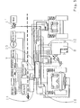
- FIG. 2 is a block diagram of an inventive device Mobile excavator shown.
- control signals for transmission circuit, accelerator pedal, hydraulic motor and pendulum axle lock by electrical switch signals (analog and digital) passed to the superstructure electronics; from there the control signals arrive via a communication connection 9 to the undercarriage electronics 10.
- electrical switch signals analog and digital
- the solenoid valves advantageously housed in the undercarriage become; their control is carried out by means of Undercarriage electronics 10.
- the transmission control block 11 directly at the transmission 8 or at another, suitable place in the To arrange undercarriage.
- an additional function "front axle deactivation" via a solenoid valve provided in the transmission control block, which of the undercarriage electronics electrically is controllable.
- this signal is processed by the undercarriage electronics 10 so that by means of this speed information the switch-back electronically.
- an automatic Gear shift provided.
- the functions in the undercarriage are logically linked. This results in a significant effort reduction and in an increase in security during the Operation. For example, in a wheeled excavator with long outrigger and four - point support the outriggers extended and locked before with the boom may be worked.
- one electrically proportional adjustable hydraulic motor with superimposed pressure control to use its proportional valve of the undercarriage electronics 10 is controllable.
- the engine has one Brake valve, with secondary-acting pressure relief valves are provided between the engine and brake valve. At the Startup, this engine stands on maximum displacement and consequently torque, thus allowing better acceleration the machine from the state.
- the adjustment The engine can therefore be dependent on a smaller displacement from the accelerator pedal position and the input speed be controlled by the transmission.
- the accelerator pedal position can also be adjusted by means of a pressure sensor between "accelerator pedal” and "slide drive" are detected.
- This concept also has the advantage that the Engine in braking mode targeted to larger displacement can be adjusted, causing an overdrive on descent is prevented. If the accelerator pedal is retracted when driving downhill, increases the braking torque due to the adjustment of the Hydromotors on larger displacement over a vorstorede Time constantly and the machine comes to a halt. One Overclocking can thus almost be ruled out. at a descent is forced so that the driver, the accelerator pedal to be able to drive. The from the hydraulic engine The oil pumped to the tank is cooled, causing overheating the units in the undercarriage is largely avoided.
- a particularly advantageous variant of the invention provides, also the hydraulic Connections between upper and undercarriage on one Reduce connection.
- the number is limited the line connections between the upper and lower carriage three, namely a hydraulic, an electrical and a Communication link. This makes the whole Undercarriage as a closed system.
- the number of oil pumps in the superstructure is accordingly of four reduced to a main work pump 1 '.
- All control commands go in the form of electrical digital or analog Signals to the on-board electronics in the superstructure and of there via the communication link to the undercarriage electronics 10, which forwards the control signals to the actuators.
- important status and diagnostic data from the actuators and sensors from the undercarriage diagnosed in the undercarriage electronics 10 and on the Communication link 9 to the on-board electronics in the uppercarriage reported ("fault management"), wherein after the evaluation Emergency or emergency operation programs can be executed.
- main working pump 1 is the pressure of the highest Consumer reported from the bottom to the superstructure.
- the flow of oil to the consumers in the undercarriage is determined by the undercarriage electronics 10. This is especially important in the event that in the labor several consumers are needed at the same time (e.g. Dozer blade, etc.).
- Another variant for the detection of the highest-highest Consumer provides, interconnected check valves use the load pressure of the highest load consumer lead via a hydraulic signaling line to the superstructure. In contrast to the first variant, this is an additional hydraulic connection between upper and lower chassis needed.
- the hydraulic power for brake, steering, hydraulic motor and blade is from the central pressure oil supply branched off the undercarriage.
- the control oil is preferably by a control oil from the high pressure supply the undercarriage by a pressure reduction diverted. The control of all consumers in the undercarriage thus takes place through the undercarriage electronics 10th
- the steer-by-wire component works as follows: The steering wheel movements are in the steer-by-wire unit in the superstructure converted into electrical signals and the superstructure electronics guided. From there comes this information via the communication link 9 to the undercarriage electronics 10. This then controls the hydraulic steer-by-wire Unit 13 electrically on. In the steer-by-wire unit The electrical signals are converted into hydraulic signals and passed on to the steering cylinder.
- the Steer-by-wire unit 13 in the undercarriage are hydraulic accumulators intended for emergency operation.
- the Steer-by-wire unit 13 can both be directly on the axle or be mounted in a suitable place in the undercarriage.
Landscapes
- Engineering & Computer Science (AREA)
- Mining & Mineral Resources (AREA)
- Civil Engineering (AREA)
- General Engineering & Computer Science (AREA)
- Structural Engineering (AREA)
- Operation Control Of Excavators (AREA)
- Motor Power Transmission Devices (AREA)
- Regulating Braking Force (AREA)
- Control Of Fluid Gearings (AREA)
- Control Of Transmission Device (AREA)
Abstract
Description
- Figur 1:
- Ein Blockdiagramm eines Mobilbaggers nach dem Stand der Technik;
- Figur 2:
- Ein Blockdiagramm eines Mobilbaggers gemäß einer ersten Ausführungsform der Erfindung; und
- Figur 3:
- Ein Blockdiagramm eines Mobilbaggers gemäß einer weiteren Ausführungsform der Erfindung.
- 1,1'
- Hauptarbeitspumpe
- 2
- Vorsteuerpumpe
- 3
- Bremspumpe
- 4
- Lenkpumpe
- 5
- Bremskompaktblock
- 6
- Lenkeinheit
- 7
- Lenkrad
- 8
- Getriebe
- 9
- Kommunikationsverbindung
- 10
- Unterwagenelektronik
- 11
- Getriebesteuerblock
- 12
- Drehzahlsensor
- 13
- Steer-by-wire Einheit
- 14
- Brake-by-wire Einheit
Claims (33)
- Arbeitsmaschine mit einem hydrostatischen Fahrantrieb, insbesondere Mobilbagger, mit einem Unterwagen, in dem ein Fahrmotor zum Antrieb der Räder vorgesehen ist und einem auf dem Unterwagen drehbar angeordneten Oberwagen, der eine Pumpe zur Versorgung des Fahrantriebs mit Druckmittel umfasst, wobei zwischen Ober- und Unterwagen eine Drehdurchführung angeordnet ist, dadurch gekennzeichnet, dass im Unterwagen eine oder mehrere Elektronikkomponenten als Unterwagenelektronik (10) vorgesehen sind, die der Steuerung und/oder Regelung der Unterwagenkomponenten dienen.
- Arbeitsmaschine nach Anspruch 1, dadurch gekennzeichnet, dass die Unterwagenelektronik (10) über eine Kommunikationsverbindung (9) mit der Bordelektronik im Oberwagen mittels der Drehdurchführung verbunden ist, wobei die Versorgungsspannung für die Unterwagenelektronik (10) über die Drehdurchführung erfolgt.
- Arbeitsmaschine nach Anspruch 1 oder 2, dadurch gekennzeichnet, dass zwischen Ober- und Unterwagen eine Steuerleitung vorgesehen ist.
- Arbeitsmaschine nach einem der vorangehenden Ansprüche, dadurch gekennzeichnet, dass die Komponenten, insbesondere Sensoren und Aktuatoren im Unterwagen von der Unterwagenelektronik (10) elektrisch und/oder hydraulisch direkt ansteuerbar und diagnostizierbar sind.
- Arbeitsmaschine nach einem der vorangehenden Ansprüche, dadurch gekennzeichnet, dass der Getriebesteuerblock (11) direkt am Getriebe (8) im Unterwagen angeordnet ist.
- Arbeitsmaschine nach einem der vorangehenden Ansprüche, dadurch gekennzeichnet, dass eine Funktion "Vorderachsabschaltung" über ein im Getriebesteuerblock (11) vorgesehenes Magnetventil, welches von der Unterwagenelektronik (10) elektrisch ansteuerbar ist, vorgesehen ist.
- Arbeitsmaschine nach einem der vorangehenden Ansprüche, dadurch gekennzeichnet, dass eine Rückschaltsperre vorgesehen ist, die von der Unterwagenelektronik (10) elektronisch ansteuerbar ist, wobei die An- und/oder Abtriebsdrehzahl durch einen vorgesehenen Drehzahlsensor (12) messbar und von der Unterwagenelektronik (10) auswertbar ist.
- Arbeitsmaschine nach einem der vorangehenden Ansprüche, dadurch gekennzeichnet, dass eine automatische Gangschaltung vorgesehen ist, die von der Unterwagenelektronik (10) anhand von Signalen des Drehzahlgebers und der Schluckvolumeneinstellung ansteuerbar ist.
- Arbeitsmaschine nach einem der vorangehenden Ansprüche, dadurch gekennzeichnet, dass die Funktionen im Unterwagen über die Unterwagenelektronik (10) logisch verknüpft sind.
- Arbeitsmaschine nach einem der vorangehenden Ansprüche, dadurch gekennzeichnet, dass ein elektrisch proportional verstellbarer Hydromotor mit überlagerter Druckregelung vorgesehen ist, dessen Proportionalventil von der Unterwagenelektronik (10) ansteuerbar ist, wobei der Motor über ein Bremsventil verfügt und wobei sekundär wirkende Druckbegrenzungsventile zwischen Motor und Bremsventil vorgesehen sind.
- Arbeitsmaschine nach Anspruch 10, dadurch gekennzeichnet, dass die Verstellung des Motors auf kleineres Schluckvolumen abhängig von der Fahrpedalstellung und der An- und/oder Abtriebsdrehzahl des Getriebes steuerbar ist.
- Arbeitsmaschine nach Anspruch 11, dadurch gekennzeichnet, dass am Fahrpedal ein analoger Sensor oder ein Steuerdrucksensor vorgesehen ist zur Erkennung der Fahrpedalstellung.
- Arbeitsmaschine nach einem der vorangehenden Ansprüche, dadurch gekennzeichnet, dass die hydraulischen Verbindungen zwischen Ober- und Unterwagen auf eine Verbindung reduziert sind, wodurch die Anzahl der Leitungsverbindungen zwischen Ober- und Unterwagen auf drei, nämlich eine hydraulische, eine elektrische und eine Kommunikationsverbindung (9) beschränkt ist.
- Arbeitsmaschine nach Anspruch 13, dadurch gekennzeichnet, dass im Oberwagen lediglich eine Hauptarbeitspumpe(1') angeordnet ist.
- Arbeitsmaschine nach Anspruch 14, dadurch gekennzeichnet, dass die Hauptarbeitspumpe(1') über eine hochdruckunabhängige Bedarfsstromregelung verfügt.
- Arbeitsmaschine nach Anspruch 15, dadurch gekennzeichnet, dass in den lastdruckführenden Leitungen Drucksensoren vorgesehen sind, deren Signale über die Unterwagenelektronik (10) an die Oberwagenelektronik zum Zweck der Hauptpumpenregelung übermittelbar sind.
- Arbeitsmaschine nach einem der vorangehenden Ansprüche, dadurch gekennzeichnet, dass für Lenkung und/oder Bremse Steer-by-wire bzw. Brake-by-wire Systeme vorgesehen sind.
- Arbeitsmaschine nach Anspruch 17, dadurch gekennzeichnet, dass im Unterwagen eine proportional-elektrohydraulische Steer-by-wire Einheit (13) und/oder eine Brake-by-wire Einheit (14) angeordnet ist.
- Arbeitsmaschine nach Anspruch 18, dadurch gekennzeichnet, dass elektronische Steuerung der Steer-by-wire Einheit (13) und der Brake-by-wire Einheit (14) in der Unterwagenelektronik (10) integriert oder in getrennten Komponenten untergebracht ist.
- Arbeitsmaschine nach Anspruch 17, 18 oder 19, dadurch gekennzeichnet, dass mittels der Steer-by-wire Einheit im Oberwagen durch einen vorgesehenen Elektromotor Lenkkräfte auf das Lenkrad (7) simulierbar sind.
- Arbeitsmaschine nach einem der vorangehenden Ansprüche, dadurch gekennzeichnet, dass die Lenkung optional mittels Joysticks bedienbar ist.
- Arbeitsmaschine nach einem der Ansprüche 17 bis 19, dadurch gekennzeichnet, dass Sensoren vorgesehen sind, welche die Bremspedalbewegungen erfassen und in elektrische Signale umsetzen, die zur Steuerung der Brake-by-wire Einheit (14) an die Unterwagenelektronik (10) weiterleitbar sind.
- Arbeitsmaschine nach einem der Ansprüche 17 bis 22, dadurch gekennzeichnet, dass in der Brake-by-wire Einheit (14) im Unterwagen hydraulische Speicher für einen Notbetrieb vorgesehen sind.
- Arbeitsmaschine nach einem der vorangehenden Ansprüche, dadurch gekennzeichnet, dass zur Realisierung von ABS bzw. ASR-Systemen Raddrehzahlsensoren vorgesehen sind.
- Arbeitsmaschine nach einem der vorangehenden Ansprüche, dadurch gekennzeichnet, dass die hydraulische Leistung für Bremse, Lenkung, Hydromotor und weitere Verbraucher aus der zentralen Druckölversorgung des Unterwagens abgezweigt wird, wobei die Ansteuerung aller Verbraucher im Unterwagen durch die Unterwagenelektronik (10) erfolgt.
- Verfahren zum Betreiben einer Arbeitsmaschine mit einem hydrostatischen Fahrantrieb, insbesondere eines Mobilbaggers, mit einem Unterwagen, in dem ein Fahrmotor zum Antrieb der Räder vorgesehen ist und einem auf dem Unterwagen drehbar angeordneten Oberwagen, der eine Pumpe zur Versorgung des Fahrantriebs mit Druckmittel umfasst, wobei zwischen Ober- und Unterwagen eine Drehdurchführung angeordnet ist, insbesondere nach einem der Ansprüche 1 bis 25, dadurch gekennzeichnet, dass im Unterwagen eine oder mehrere Elektronikkomponenten als Unterwagenelektronik (10) eingesetzt werden, die der Steuerung und/oder Regelung der Unterwagenkomponenten dienen.
- Verfahren nach Anspruch 26, dadurch gekennzeichnet, dass die Sensoren und Aktuatoren im Unterwagen von der Unterwagenelektronik elektrisch und/oder hydraulisch direkt angesteuert und diagnostiziert werden.
- Verfahren nach Anspruch 26 oder 27, dadurch gekennzeichnet, dass die Funktionen im Unterwagen über die Unterwagenelektronik (10) logisch verknüpft werden.
- Verfahren nach einem der Ansprüche 26 - 28, dadurch gekennzeichnet, dass die hydraulische Leistung für Bremse, Lenkung, Hydromotor und weitere Verbraucher aus der zentralen Druckölversorgung des Unterwagens abgezweigt wird, die Ansteuerung aller Verbraucher im Unterwagen durch die Unterwagenelektronik (10) erfolgt.
- Verfahren nach einem der Ansprüche 26-29, dadurch gekennzeichnet, dass die Hauptarbeitspumpe (1, 1') über eine hochdruckunabhängige Bedarfsstromregelung verfügt, wobei der Druck des lasthöchsten Verbrauchers vom Unterzum Oberwagen gemeldet wird und beim Erreichen der Leistungsgrenze der Ölstrom zu den Verbrauchern gleichmäßig reduziert wird und wobei der Ölstrom zu den Verbrauchern im Unterwagen von der Unterwagenelektronik (10) bestimmt wird.
- Verfahren nach Anspruch 30, dadurch gekennzeichnet, dass zur Erkennung des lasthöchsten Verbrauchers von in den lastdruckführenden Leitungen vorgesehenen Sensoren über die Unterwagenelektronik (10) an die Oberwagenelektronik übermittelt werden.
- Verfahren nach einem der Ansprüche 26 - 31, dadurch gekennzeichnet, dass der Motor abhängig von der Fahrpedalstellung und der An- und/oder Abtriebsdrehzahl des Getriebes (8) gesteuert wird.
- Verfahren nach einem der Ansprüche 26 - 32, dadurch gekennzeichnet, dass die Lenkung optional über Joysticks erfolgt.
Applications Claiming Priority (3)
| Application Number | Priority Date | Filing Date | Title |
|---|---|---|---|
| DE10153458 | 2001-10-30 | ||
| DE10153458A DE10153458A1 (de) | 2001-10-30 | 2001-10-30 | Arbeitsmaschine und Verfahren zum Betreiben einer Arbeitsmaschine |
| PCT/EP2002/011872 WO2003038200A1 (de) | 2001-10-30 | 2002-10-24 | Arbeitsmaschine und verfahren zum betreiben einer arbeitsmaschine |
Publications (2)
| Publication Number | Publication Date |
|---|---|
| EP1440211A1 EP1440211A1 (de) | 2004-07-28 |
| EP1440211B1 true EP1440211B1 (de) | 2005-04-27 |
Family
ID=7704168
Family Applications (1)
| Application Number | Title | Priority Date | Filing Date |
|---|---|---|---|
| EP02802301A Expired - Lifetime EP1440211B1 (de) | 2001-10-30 | 2002-10-24 | Arbeitsmaschine und verfahren zum betreiben einer arbeitsmaschine |
Country Status (7)
| Country | Link |
|---|---|
| US (1) | US20040249537A1 (de) |
| EP (1) | EP1440211B1 (de) |
| JP (1) | JP2005507471A (de) |
| KR (1) | KR20050039716A (de) |
| CN (1) | CN1276156C (de) |
| DE (2) | DE10153458A1 (de) |
| WO (1) | WO2003038200A1 (de) |
Cited By (1)
| Publication number | Priority date | Publication date | Assignee | Title |
|---|---|---|---|---|
| WO2021040601A1 (en) * | 2019-08-23 | 2021-03-04 | Epiroc Rock Drills Aktiebolag | Method and system for controlling a mining and/or construction machine |
Families Citing this family (6)
| Publication number | Priority date | Publication date | Assignee | Title |
|---|---|---|---|---|
| DE10343844A1 (de) * | 2003-09-23 | 2005-04-28 | Zahnradfabrik Friedrichshafen | Berührungslose Datenübertragung |
| KR100655330B1 (ko) * | 2005-12-23 | 2006-12-08 | 두산인프라코어 주식회사 | 전동 지게차의 경사 작업시 자동 정지장치 |
| DE202008008044U1 (de) * | 2008-06-16 | 2009-11-05 | Liebherr-Hydraulikbagger Gmbh | Verfahrbares Arbeitsgerät |
| NL1040157C2 (nl) * | 2013-04-12 | 2014-10-14 | Hudson Bay Holding B V | Mobiele inrichting met besturingssysteem. |
| KR101747578B1 (ko) * | 2013-08-30 | 2017-06-14 | 히다찌 겐끼 가부시키가이샤 | 작업 기계 |
| CN104691529A (zh) * | 2014-01-23 | 2015-06-10 | 青岛科瑞特激光设备有限公司 | 自走式谷物联合收割机液压驱动桥行车制动电液控制装置 |
Family Cites Families (14)
| Publication number | Priority date | Publication date | Assignee | Title |
|---|---|---|---|---|
| US4811561A (en) * | 1986-04-08 | 1989-03-14 | Vickers, Incorporated | Power transmission |
| DE3701554A1 (de) * | 1987-01-21 | 1988-08-04 | Duerr Gmbh & Co | Maschinenanlage mit mehreren aktoren |
| US5018384A (en) * | 1989-07-21 | 1991-05-28 | Nippon Seiko Kabushiki Kaisha | Rotational speed detector |
| DE19538416A1 (de) * | 1995-09-11 | 1997-03-13 | Orenstein & Koppel Ag | Verfahren und Einrichtung zur lastabhängigen automatischen Umschaltung von Fahrmotoren |
| US5884206A (en) * | 1996-11-08 | 1999-03-16 | Samsung Heavy Industries Co., Ltd. | Distributed control system for heavy construction machine |
| US6336067B1 (en) * | 1998-08-12 | 2002-01-01 | Hitachi Construction Machinery Co., Ltd. | Electronic control system and control device for construction machine |
| DE19850902C2 (de) * | 1998-11-05 | 2001-07-12 | Manfred Scherger Baumaschinen | Schnellmontagebaugruppe für einen Turmdrehkran |
| US6278204B1 (en) * | 1999-06-18 | 2001-08-21 | Eugene Roland Frenette | Method of converting internal combustion engine into electrically driven engine |
| DE19956402A1 (de) * | 1999-11-24 | 2001-05-31 | Linde Ag | Fahrzeug, insbesondere Mobilbagger |
| EP1257903A4 (de) * | 2000-02-01 | 2004-10-13 | Delphi Tech Inc | Multimodul-control-by-wire-architektur |
| DE10037676C1 (de) * | 2000-07-26 | 2002-05-23 | Jungheinrich Ag | Vorrichtung zur Regelung eines Antriebssystems für ein Flurförderzeug |
| WO2002016181A1 (de) * | 2000-08-22 | 2002-02-28 | Continental Teves Ag & Co. Ohg | Verfahren zum betreiben eines kraftfahrzeugregelungssystems und vorrichtung zur durchführung des verfahrens |
| US6695748B2 (en) * | 2000-09-08 | 2004-02-24 | Borgwarner Inc. | Transmission control apparatus |
| DE10128209A1 (de) * | 2001-06-11 | 2003-01-09 | Brueninghaus Hydromatik Gmbh | Hydrostatische Kolbenmaschine und Übertragungssystem |
-
2001
- 2001-10-30 DE DE10153458A patent/DE10153458A1/de not_active Withdrawn
-
2002
- 2002-10-24 CN CNB028185870A patent/CN1276156C/zh not_active Expired - Fee Related
- 2002-10-24 WO PCT/EP2002/011872 patent/WO2003038200A1/de not_active Ceased
- 2002-10-24 EP EP02802301A patent/EP1440211B1/de not_active Expired - Lifetime
- 2002-10-24 KR KR1020047006438A patent/KR20050039716A/ko not_active Withdrawn
- 2002-10-24 JP JP2003540453A patent/JP2005507471A/ja active Pending
- 2002-10-24 DE DE50202947T patent/DE50202947D1/de not_active Expired - Lifetime
- 2002-10-24 US US10/493,807 patent/US20040249537A1/en not_active Abandoned
Cited By (2)
| Publication number | Priority date | Publication date | Assignee | Title |
|---|---|---|---|---|
| WO2021040601A1 (en) * | 2019-08-23 | 2021-03-04 | Epiroc Rock Drills Aktiebolag | Method and system for controlling a mining and/or construction machine |
| AU2020339521B2 (en) * | 2019-08-23 | 2025-08-14 | Epiroc Rock Drills Aktiebolag | Method and system for controlling a mining and/or construction machine |
Also Published As
| Publication number | Publication date |
|---|---|
| DE50202947D1 (de) | 2005-06-02 |
| US20040249537A1 (en) | 2004-12-09 |
| EP1440211A1 (de) | 2004-07-28 |
| KR20050039716A (ko) | 2005-04-29 |
| CN1276156C (zh) | 2006-09-20 |
| DE10153458A1 (de) | 2003-05-15 |
| CN1556888A (zh) | 2004-12-22 |
| JP2005507471A (ja) | 2005-03-17 |
| WO2003038200A1 (de) | 2003-05-08 |
Similar Documents
| Publication | Publication Date | Title |
|---|---|---|
| DE102006000784B4 (de) | Arbeitsmaschinen-Hydrauliksteuersystem | |
| EP2269880A1 (de) | Abbremsung einer Zugfahrzeug-Anhänger-Kombination | |
| WO2010072299A1 (de) | Hydrostatisches antriebssystem | |
| EP1519852A1 (de) | Verfahren und vorrichtung zur steuerung von funktionen eines arbeitsfahrzeuges | |
| EP1574626B1 (de) | Hydraulisches passives Federungssystem | |
| DE10154650C1 (de) | Kettenfahrzeug | |
| EP1818245A1 (de) | Radantriebsvorrichtung und Verfahren für eine Radantriebsvorrichtung | |
| DE112006002605B4 (de) | Massenkraftsteuerung in elektrisch angetriebener Arbeitsmaschine | |
| DE60126406T2 (de) | Elektrische hilfsaggregate für einen vierradantrieb | |
| EP1440211B1 (de) | Arbeitsmaschine und verfahren zum betreiben einer arbeitsmaschine | |
| DE10154651C1 (de) | Kettenfahrzeug mit einem Antriebssystem | |
| DE10324723B4 (de) | Federspeicher-Feststellbremse für Fahrzeuge mit Fremdkraftbremsanlage | |
| DE102010054108A1 (de) | Ventilanordnung zur Steuerung eines Zusatz-Lenksystems bei mehrachsigen Fahrzeugen, insbesondere Mobilkranen | |
| DE112019003034T5 (de) | Hydraulikkreis | |
| DE10197080T5 (de) | Baumaschine mit Traktionssteuerung | |
| EP3512732B1 (de) | Hydrauliksystem | |
| DE102018127544A1 (de) | Arbeitsfahrzeug mit geschwindigkeitsabhängiger Lenkung | |
| EP2070863B1 (de) | Verfahren zur Stillstandregelung eines Nutzfahrzeuges | |
| EP1527981B1 (de) | Notfall-Lenksystem für ein Gleis- oder Raupenfahrzeug | |
| DE102013113206A1 (de) | Batterie-elektrisch betriebenes Flurförderzeug | |
| EP3461707B1 (de) | Steuersystem einer hydraulisch betätigten bremseinrichtung | |
| DE102012020821B4 (de) | Notantrieb für ein Baugerät und Verfahren zum Betrieb des Notantriebs | |
| DE10135862A1 (de) | Fahrzeuglenkung | |
| EP4402381A1 (de) | Energieeffiziente elektrisch-hydraulische steueranordnung | |
| EP2341190B1 (de) | Mobiles Arbeitsgerät mit hydraulische Anordnung |
Legal Events
| Date | Code | Title | Description |
|---|---|---|---|
| PUAI | Public reference made under article 153(3) epc to a published international application that has entered the european phase |
Free format text: ORIGINAL CODE: 0009012 |
|
| 17P | Request for examination filed |
Effective date: 20040123 |
|
| AK | Designated contracting states |
Kind code of ref document: A1 Designated state(s): AT BE BG CH CY CZ DE DK EE ES FI FR GB GR IE IT LI LU MC NL PT SE SK TR |
|
| GRAP | Despatch of communication of intention to grant a patent |
Free format text: ORIGINAL CODE: EPIDOSNIGR1 |
|
| GRAS | Grant fee paid |
Free format text: ORIGINAL CODE: EPIDOSNIGR3 |
|
| GRAA | (expected) grant |
Free format text: ORIGINAL CODE: 0009210 |
|
| AK | Designated contracting states |
Kind code of ref document: B1 Designated state(s): DE FR GB IT NL SE |
|
| RBV | Designated contracting states (corrected) |
Designated state(s): DE FR GB IT NL SE |
|
| REG | Reference to a national code |
Ref country code: GB Ref legal event code: FG4D Free format text: NOT ENGLISH |
|
| GBT | Gb: translation of ep patent filed (gb section 77(6)(a)/1977) |
Effective date: 20050427 |
|
| REG | Reference to a national code |
Ref country code: IE Ref legal event code: FG4D Free format text: LANGUAGE OF EP DOCUMENT: GERMAN |
|
| REF | Corresponds to: |
Ref document number: 50202947 Country of ref document: DE Date of ref document: 20050602 Kind code of ref document: P |
|
| REG | Reference to a national code |
Ref country code: SE Ref legal event code: TRGR |
|
| ET | Fr: translation filed | ||
| PLBE | No opposition filed within time limit |
Free format text: ORIGINAL CODE: 0009261 |
|
| STAA | Information on the status of an ep patent application or granted ep patent |
Free format text: STATUS: NO OPPOSITION FILED WITHIN TIME LIMIT |
|
| 26N | No opposition filed |
Effective date: 20060130 |
|
| PGFP | Annual fee paid to national office [announced via postgrant information from national office to epo] |
Ref country code: NL Payment date: 20061003 Year of fee payment: 5 |
|
| PGFP | Annual fee paid to national office [announced via postgrant information from national office to epo] |
Ref country code: SE Payment date: 20061004 Year of fee payment: 5 |
|
| PGFP | Annual fee paid to national office [announced via postgrant information from national office to epo] |
Ref country code: GB Payment date: 20061018 Year of fee payment: 5 |
|
| PGFP | Annual fee paid to national office [announced via postgrant information from national office to epo] |
Ref country code: IT Payment date: 20061031 Year of fee payment: 5 |
|
| EUG | Se: european patent has lapsed | ||
| GBPC | Gb: european patent ceased through non-payment of renewal fee |
Effective date: 20071024 |
|
| NLV4 | Nl: lapsed or anulled due to non-payment of the annual fee |
Effective date: 20080501 |
|
| REG | Reference to a national code |
Ref country code: FR Ref legal event code: ST Effective date: 20080630 |
|
| PG25 | Lapsed in a contracting state [announced via postgrant information from national office to epo] |
Ref country code: NL Free format text: LAPSE BECAUSE OF NON-PAYMENT OF DUE FEES Effective date: 20080501 Ref country code: SE Free format text: LAPSE BECAUSE OF NON-PAYMENT OF DUE FEES Effective date: 20071025 |
|
| PGFP | Annual fee paid to national office [announced via postgrant information from national office to epo] |
Ref country code: FR Payment date: 20061010 Year of fee payment: 5 |
|
| PG25 | Lapsed in a contracting state [announced via postgrant information from national office to epo] |
Ref country code: GB Free format text: LAPSE BECAUSE OF NON-PAYMENT OF DUE FEES Effective date: 20071024 |
|
| PG25 | Lapsed in a contracting state [announced via postgrant information from national office to epo] |
Ref country code: FR Free format text: LAPSE BECAUSE OF NON-PAYMENT OF DUE FEES Effective date: 20071031 |
|
| PG25 | Lapsed in a contracting state [announced via postgrant information from national office to epo] |
Ref country code: IT Free format text: LAPSE BECAUSE OF NON-PAYMENT OF DUE FEES Effective date: 20071024 |
|
| PGFP | Annual fee paid to national office [announced via postgrant information from national office to epo] |
Ref country code: DE Payment date: 20181009 Year of fee payment: 17 |
|
| REG | Reference to a national code |
Ref country code: DE Ref legal event code: R119 Ref document number: 50202947 Country of ref document: DE |
|
| PG25 | Lapsed in a contracting state [announced via postgrant information from national office to epo] |
Ref country code: DE Free format text: LAPSE BECAUSE OF NON-PAYMENT OF DUE FEES Effective date: 20200501 |