EP1440252B1 - Courroie pour transmission a variation continue - Google Patents
Courroie pour transmission a variation continue Download PDFInfo
- Publication number
- EP1440252B1 EP1440252B1 EP02800612A EP02800612A EP1440252B1 EP 1440252 B1 EP1440252 B1 EP 1440252B1 EP 02800612 A EP02800612 A EP 02800612A EP 02800612 A EP02800612 A EP 02800612A EP 1440252 B1 EP1440252 B1 EP 1440252B1
- Authority
- EP
- European Patent Office
- Prior art keywords
- belt
- endless band
- toothing
- transmission members
- members
- Prior art date
- Legal status (The legal status is an assumption and is not a legal conclusion. Google has not performed a legal analysis and makes no representation as to the accuracy of the status listed.)
- Expired - Lifetime
Links
Images


Classifications
-
- F—MECHANICAL ENGINEERING; LIGHTING; HEATING; WEAPONS; BLASTING
- F16—ENGINEERING ELEMENTS AND UNITS; GENERAL MEASURES FOR PRODUCING AND MAINTAINING EFFECTIVE FUNCTIONING OF MACHINES OR INSTALLATIONS; THERMAL INSULATION IN GENERAL
- F16G—BELTS, CABLES, OR ROPES, PREDOMINANTLY USED FOR DRIVING PURPOSES; CHAINS; FITTINGS PREDOMINANTLY USED THEREFOR
- F16G5/00—V-belts, i.e. belts of tapered cross-section
- F16G5/16—V-belts, i.e. belts of tapered cross-section consisting of several parts
- F16G5/166—V-belts, i.e. belts of tapered cross-section consisting of several parts with non-metallic rings
Definitions
- the present invention relates to a belt for a continuously variable transmission (CVT).
- CVT continuously variable transmission
- continuously variable transmissions or variable speed drives
- belts with a substantially trapezial cross section V-belts
- V-belts which are provided with lateral friction surfaces designed to co-operate with respective sides of pulleys with trapezial or vee-shaped races.
- Variation of the transmission ratio is performed by modifying, via mechanisms of a known type, the width of the race of the pulleys and consequently the winding diameter of the belt.
- belts having a body made of elastomeric material and provided with longitudinal cord reinforcing elements designed to bestow the necessary mechanical tensile strength on the belt.
- the body made of elastomeric material is normally provided with an internal indentation and an external indentation, having the purpose of bestowing on the belt a good flexibility, thus enabling the belt to operate with reduced winding diameters, at the same time maintaining a sufficiently extended lateral surface.
- transverse stiffening elements which are set on top of respective teeth of the external indentation and internal indentation and are designed to limit the transverse compression deformations of the belt itself.
- the stiffening elements set on top of each pair of teeth set opposite to one another, i.e. the inner one and the outer one respectively, can be connected by a connection member extending through the body of the belt.
- the above-described belts in which power transmission occurs through direct contact between the elastomeric material of the body and the pulleys, are not suitable for high-power drives, such as, for instance, the ones that can be employed in variable-speed drives for motor vehicles.
- belts have been proposed for dry power drives, which comprise an endless band having an elastomeric body, provided with an internal toothing and an external toothing and a plurality of longitudinal cord inserts embedded in the body, as well as a plurality of discrete transmission members overmoulded on the endless band, so as to embed one tooth of the external toothing and one tooth of the internal toothing.
- An example of belts of this type is illustrated in EP-A-1 106 865.
- An object of the present invention is to devise an improved CVT belt which allows to increase torque transmission and belt life and is still relatively simple and unexpensive to manufacture.
- a CVT belt comprising an endless flexible band having a body made of elastomeric material and a plurality of longitudinal cord inserts embedded in said body, and a plurality of transmission members fixed along the endless band and laterally delimited by mutually inclined friction flanks for engagement with a vee-shaped race of a pulley, characterised in that each transmission member includes an inner block moulded around said endless band so as to completely surround a length of said endless band and be secured thereto, and a pair of half-shell covering members transversally fitted onto said inner block and defining said friction flanks.
- numeral 1 designates, as a whole, a belt for a continuously variable transmission (CVT).
- CVT continuously variable transmission
- the belt 1 basically comprises a closed-loop endless flexible band 2, having the purpose of transmitting the load, and a plurality of transmission members 3, anchored to the endless band 2 adjacent to one another, having a substantially vee-shaped cross section in order to co-operate by friction, by means of respective pairs of mutually inclined friction flanks 4, with a vee-shaped race 5 of a pulley P (schematically indicated with a dashed line in Figures 1 and 3).
- the endless band 2 basically comprises a toothed body 6 made of elastomeric material, for example HNBR, and a plurality of cord inserts 7, which are substantially inextensible and are embedded in the body 6 and extend longitudinally and parallel to one another along the body itself.
- the inserts 7, produced according to a conventional spiralling technique, may be made of glass or aramidic fibres, for example of the material known under the trade name Kevlar®.
- the band 2 comprises an external toothing 8, i.e., a toothing made on an outer surface 9 of the body 6.
- the toothing 8 comprises a plurality of teeth 10 alternated with recesses 11.
- the teeth 10 conveniently present a substantially semicircular or parabolic cross section, but can have any shape suitable for ensuring a stable coupling with the transmission members 3.
- the transmission members 3 each comprise an inner block 12, which is overmoulded around the endless band 2 so as to completely surround a length thereof and embed a respective tooth 10 of the endless band 2, and a friction coating 13 defining the flanks 4 that co-operate with the race 5 of the pulley.
- each transmission member 3 has a substantially vee-shaped cross section (Figure 3), and presents a central through cavity 14 engaged by, and mating in shape with, the endless band 2 ( Figure 2).
- the cavity 14 is delimited, on the side facing the inside of the belt 1, by a plane surface 15 and, on the side facing the toothing 8, presents a recess 16, the shape of which is complementary to the shape of the corresponding tooth 10.
- the friction coating 13 is made up of a pair of half-shell covering elements 20, which are fitted transversely on the inner block 12, on opposite sides of the endless band 2, so as to substantially mate with one another along a median plane M of the belt 1 (figure 3).
- the covering elements 20 are conveniently made of a plastic material having predetermined frictional properties and good resistance to wear, such as, for example, a polyamide with glass-fibre filler or a fluoropolymer of the class of materials known under the trade name of MARLON-H.
- a plastic material having predetermined frictional properties and good resistance to wear such as, for example, a polyamide with glass-fibre filler or a fluoropolymer of the class of materials known under the trade name of MARLON-H.
- An example of a material that can be used is MARLON-H82 produced by M.A.P. s.r.l.
- the covering members 20 each present a cavity 24 having a shape corresponding to half of the respective inner block 12, and comprise a pair of front walls 25, an inner base wall 26, an outer base wall 27 and a side wall 28, one outer surface of which defines a flank 4 of the transmission member 3 (figure 3).
- the front walls 25 present respective median slits 30 elongated in a direction perpendicular to the plane M and open towards the plane M, so as to enable insertion of the endless band 2.
- the edges of the slits 30 are mutually convergent towards plane M.
- the flanks 4 of the transmission members 3 conveniently present one or more grooves 31, which extend longitudinally, i.e., from the inner base wall 26 to the outer base wall 27, with the purpose of dividing the flanks 4 into one or more areas 4a, 4b of contact with the pulley (figure 4).
- each transmission member 3 presents, in a longitudinal section, a shape which is tapered towards the inside of the belt 1, which is necessary for enabling small winding diameters of the belt 1 ( Figure 1) to be obtained without interference between adjacent transmission members 3.
- the transmission members 3 are slightly tapered also towards the outside, starting from the endless band 2.
- a process for manufacturing the belt 1 is described in what follows.
- the endless band 2 is produced using known techniques employed in the manufacture of toothed belts.
- the endless band 2 is positioned in a mould (not illustrated) having a seat for the endless band 2, and a plurality of cavities, which are intersected by said seat, of a shape corresponding to that of the inner blocks 12 of the transmission members 3 of the belt 1, and which are equal in number to the blocks 12 themselves, in such a way that one tooth of the endless band 2 will be housed in each cavity of the mould.
- the plastic material which makes up the inner blocks 12 is injected into the aforesaid cavities, so as to overmould the inner blocks 12 of the transmission members on the endless band 2, so that they are spaced apart from one another.
- a respective pair of covering members 20 is inserted on each inner block 12.
- the covering members 20 of each pair of adjacent transmission members 3 are substantially in contact with one another at least in the proximity of the endless band 2.
- substantially in contact is here used both in the sense that the covering members 20 are actually in contact with one another and in the sense that a small clearance is left during assembly, of the order of some tenths of a millimetre, which means that during use there is an effective contact between the elements 20 in the proximity of the endless band 2 at least on the inner side of the belt 1 when the endless band 2 is flexed.
- the substantial contact between the transmission members 3 limits the oscillations of the blocks about an axis perpendicular to the plane M when the transmission members 3 come into contact with the pulley. As a result, any fatigue stresses on the endless band 2 are substantially limited.
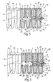
- Figure 5 is a partial illustration of a belt 35 according to a different embodiment of the invention.
- the belt 35 differs from the belt 1 described above, in that the front walls 25 of each covering member 20 are substantially parallel to one another in the portion thereof that is external to the endless band 2, except for minimum rakes.
- each pair of adjacent transmission members 3 arrange themselves in contact with one another, in an area corresponding to the portion thereof that is external to the endless band 2, in the rectilinear stretches of the belt and, in particular, in the portion of the belt which disengages from the pulley.
- the oscillations of the transmission members 3 about a transverse axis are thus reduced and, consequently, also the stresses on the endless band 2.
- Figure 6 shows a further embodiment of the present invention, referenced 36 as a whole.
- Belt 36 differs from belt 35 in that the endless band 2 has an outer toothing 8 and an inner toothing 37 provided on an inner surface 38 of the body 6 of the endless belt 2.
- the inner toothing 37 comprises a plurality of teeth 39 alternating with recesses 40; the teeth 39 of the inner toothing 37 are identical to respective teeth 10 of the outer toothing 8 and disposed on opposite sides with respect to the body 6.
- each transmission member 3 has a through cavity 14 which mates in shape with a portion of the endless belt 2, so that a tooth 10 of outer toothing 8 and a corresponding tooth 39 of inner toothing 37 are embedded in a respective inner block 12.
- the inner blocks 12 principally have the function of driving and structurally supporting the friction covering members 20 and therefore can be made from material having good structural properties but not necessarily optimal wear resistance and friction properties, while the covering members 20, which provide the belt-pulley interface enabling the friction torque transfer, can be made from a material specifically adapted to this purpose.
- the transmission belt of the present invention leads to a high torque transfer (for instance the belt is able to transfer torque values of over 90 Nm) and is therefore suited to a very wide range of motor vehicle and motorcycle applications.
Landscapes
- Engineering & Computer Science (AREA)
- General Engineering & Computer Science (AREA)
- Mechanical Engineering (AREA)
- Transmissions By Endless Flexible Members (AREA)
- Devices For Conveying Motion By Means Of Endless Flexible Members (AREA)
Abstract
Claims (11)
- Courroie de transmission CVT comprenant une bande souple sans fin (2) comportant un corps (6) constitué d'un matériau élastomère et une pluralité d'inserts longitudinaux de type cordons (7) incorporés dans ledit corps, et une pluralité d'éléments de transmission (3) fixés le long de la bande sans fin (2) et délimités latéralement par des flancs de friction mutuellement inclinés (4) pour un engagement avec la gorge en forme de V (5) d'une poulie (P), caractérisée en ce que chaque élément de transmission (3) comprend un bloc intérieur (12) moulé autour de ladite bande sans fin (2) de façon à complètement entourer une longueur de ladite bande sans fin et à être fixés à celle-ci, et une paire d'éléments de recouvrement en forme de demi-coquille (20) adaptés transversalement sur ledit bloc intérieur (12) et définissant lesdits flancs de friction (4).
- Courroie selon la revendication 1, caractérisée en ce que lesdits éléments de recouvrement (20) définissent des cavités intérieures respectives (24) recevant les moitiés respectives du bloc intérieur (12).
- Courroie selon la revendication 1 ou 2, caractérisée en ce que lesdits éléments de recouvrement (20) comprennent une paire de parois avant (25), une paroi de base intérieure (26), une paroi de base extérieure (27) et une paroi latérale (28), une surface extérieure de ladite paroi latérale (28) définissant un flanc (4) de l'élément de transmission respectif (3).
- Courroie selon la revendication 3, caractérisée en ce que lesdites parois avant (25) présentent des fentes médianes respectives (30) allongées dans une direction perpendiculaire à un plan médian M de la courroie (1) et s'ouvrent vers l'extérieur dudit plan médian (M), de façon à permettre l'insertion de ladite bande sans fin (2).
- Courroie selon la revendication 3 ou 4, caractérisée en ce que lesdits flancs (4) des éléments de transmission (3) présentent au moins une rainure longitudinale (31).
- Courroie selon l'une quelconque des revendications précédentes, caractérisée en ce que ladite bande sans fin (2) présente au moins une denture (8, 37) définie par une pluralité de dents (10, 39) espacées par des évidements (11, 40) et en ce que lesdits blocs intérieurs (12) et lesdits éléments de transmission (3) incorporent chacun au moins une dent respective (10, 39) de ladite denture (8, 37).
- Courroie selon la revendication 6, caractérisée en ce que ladite bande sans fin (2) comporte une seule denture extérieure (8).
- Courroie selon la revendication 6, caractérisée en ce que ladite bande sans fin (2) présente une denture extérieure (8) et une denture intérieure (37), et en ce que lesdits blocs intérieurs (12) desdits éléments de transmission (3) incorporent chacun une dent (10) de ladite denture extérieure (8) et une dent (39) de ladite denture intérieure (37).
- Courroie selon l'une quelconque des revendications précédentes, caractérisée en ce que lesdits éléments de transmission (3) sont agencés pour être sensiblement en contact les uns avec les autres au moins à proximité de ladite bande sans fin (2).
- Courroie selon la revendication 9, caractérisée en ce que lesdits blocs intérieurs (12) desdits éléments de transmission (3) sont espacés les uns des autres, et en ce que lesdits éléments de recouvrement (20) de chaque paire d'éléments de transmission adjacents (3) sont agencés pour être sensiblement en contact les uns avec les autres au moins à proximité de ladite bande sans fin (2).
- Courroie selon la revendication 10, caractérisée en ce que chaque paire d'éléments de transmission adjacents (3) est agencée pour être sensiblement en contact avec une autre sur toute la partie de ceux-ci s'étendant à l'extérieur de ladite bande sans fin (2).
Applications Claiming Priority (7)
| Application Number | Priority Date | Filing Date | Title |
|---|---|---|---|
| ITTO20010956 ITTO20010956A1 (it) | 2001-10-09 | 2001-10-09 | Cinghia per trasmissione a rapporto variabile in modo continuo - cvt. |
| ITTO20010956 | 2001-10-09 | ||
| ITTO20010095 | 2001-10-09 | ||
| ITTO20020031 | 2002-02-08 | ||
| IT2002TO000314A ITTO20020314A1 (it) | 2002-04-10 | 2002-04-10 | Cinghia per una trasmissione a rapporto variabile in modo continuo. |
| ITTO20020314 | 2002-04-10 | ||
| PCT/EP2002/011307 WO2003031841A1 (fr) | 2001-10-09 | 2002-10-09 | Courroie pour transmission a variation continue |
Publications (2)
| Publication Number | Publication Date |
|---|---|
| EP1440252A1 EP1440252A1 (fr) | 2004-07-28 |
| EP1440252B1 true EP1440252B1 (fr) | 2005-09-14 |
Family
ID=26332886
Family Applications (1)
| Application Number | Title | Priority Date | Filing Date |
|---|---|---|---|
| EP02800612A Expired - Lifetime EP1440252B1 (fr) | 2001-10-09 | 2002-10-09 | Courroie pour transmission a variation continue |
Country Status (3)
| Country | Link |
|---|---|
| EP (1) | EP1440252B1 (fr) |
| DE (1) | DE60206190T2 (fr) |
| WO (1) | WO2003031841A1 (fr) |
Families Citing this family (4)
| Publication number | Priority date | Publication date | Assignee | Title |
|---|---|---|---|---|
| ITTO20040185A1 (it) | 2004-03-19 | 2004-06-19 | Dayco Europe Srl | Cinghia per una trasmissione variabile con continuita' |
| NL1027685C2 (nl) * | 2004-12-08 | 2006-06-09 | Bosch Gmbh Robert | Drijfriem voor een transmissie met gebombeerde poelieschijven. |
| JP6322073B2 (ja) * | 2014-07-17 | 2018-05-09 | 三ツ星ベルト株式会社 | 動力伝動用ベルト |
| CN107816509B (zh) * | 2017-11-02 | 2021-01-19 | 陈学琴 | 活片无极变速器传动带 |
Family Cites Families (10)
| Publication number | Priority date | Publication date | Assignee | Title |
|---|---|---|---|---|
| DE850539C (de) * | 1951-06-01 | 1952-09-25 | Edmund Stelzner | Gliederkeilriemen |
| JPS5722441A (en) * | 1980-07-16 | 1982-02-05 | Nissan Motor Co Ltd | Transmission v-belt |
| US4595385A (en) * | 1984-03-26 | 1986-06-17 | Dayco Corporation | Belt construction, transverse belt element therefor and method of making the same |
| JPS61103030A (ja) * | 1984-10-24 | 1986-05-21 | Honda Motor Co Ltd | 伝動vベルト |
| JPS61140650A (ja) * | 1984-12-13 | 1986-06-27 | Daihatsu Motor Co Ltd | ブロツク式vベルト |
| JPS61286638A (ja) * | 1985-06-14 | 1986-12-17 | Honda Motor Co Ltd | 伝動ベルト |
| EP0240912A3 (fr) * | 1986-03-31 | 1990-05-30 | Mitsuboshi Belting Ltd. | Courroie de transmission pour fortes charges |
| JPH0510396A (ja) * | 1990-11-09 | 1993-01-19 | Bando Chem Ind Ltd | 高負荷伝動用vベルト及びその製造方法 |
| IT1311308B1 (it) | 1999-12-10 | 2002-03-12 | Dayco Europe Srl | Cinghia per una trasmissione a rapporto variabile in modo continuo. |
| KR100500501B1 (ko) * | 2000-05-09 | 2005-07-14 | 더 게이츠 코포레이션 | 블록식 무단 변속기용 벨트 |
-
2002
- 2002-10-09 EP EP02800612A patent/EP1440252B1/fr not_active Expired - Lifetime
- 2002-10-09 DE DE60206190T patent/DE60206190T2/de not_active Expired - Lifetime
- 2002-10-09 WO PCT/EP2002/011307 patent/WO2003031841A1/fr not_active Ceased
Also Published As
| Publication number | Publication date |
|---|---|
| EP1440252A1 (fr) | 2004-07-28 |
| DE60206190D1 (de) | 2005-10-20 |
| WO2003031841A1 (fr) | 2003-04-17 |
| DE60206190T2 (de) | 2006-06-08 |
Similar Documents
| Publication | Publication Date | Title |
|---|---|---|
| US3643518A (en) | Belt and belt drive assembly | |
| KR100500501B1 (ko) | 블록식 무단 변속기용 벨트 | |
| AU2001259834A1 (en) | Block type CVT belt | |
| JPH0158376B2 (fr) | ||
| KR100502763B1 (ko) | 횡방향으로 보강된 무단 변속기용 벨트 | |
| AU2001263253A1 (en) | Transverse reinforced CVT belt | |
| EP1106865B1 (fr) | Courroie pour transmission continûment variable | |
| WO2003031841A1 (fr) | Courroie pour transmission a variation continue | |
| EP1258652A2 (fr) | Courroie pour transmissions continûment variables | |
| EP1929179B1 (fr) | Entrainement par courroie crantee a utiliser dans de l'huile, et courroie crantee correspondante | |
| JPS61206847A (ja) | ブロツク5ベルト | |
| WO2005090823A1 (fr) | Courroie pour transmission a variation continue | |
| JPH0141967Y2 (fr) | ||
| JPH0118915Y2 (fr) | ||
| JP3579369B2 (ja) | 複合vベルト | |
| JPS62237137A (ja) | Vベルト | |
| HK1051395B (en) | Transverse reinforced cvt belt | |
| JPS61165046A (ja) | Vベルト | |
| JP2009262390A (ja) | ブロック製造用金型 | |
| AU2003256527A1 (en) | Belt |
Legal Events
| Date | Code | Title | Description |
|---|---|---|---|
| PUAI | Public reference made under article 153(3) epc to a published international application that has entered the european phase |
Free format text: ORIGINAL CODE: 0009012 |
|
| 17P | Request for examination filed |
Effective date: 20040505 |
|
| AK | Designated contracting states |
Kind code of ref document: A1 Designated state(s): AT BE BG CH CY CZ DE DK EE ES FI FR GB GR IE IT LI LU MC NL PT SE SK TR |
|
| AX | Request for extension of the european patent |
Extension state: AL LT LV MK RO SI |
|
| GRAP | Despatch of communication of intention to grant a patent |
Free format text: ORIGINAL CODE: EPIDOSNIGR1 |
|
| GRAS | Grant fee paid |
Free format text: ORIGINAL CODE: EPIDOSNIGR3 |
|
| GRAA | (expected) grant |
Free format text: ORIGINAL CODE: 0009210 |
|
| AK | Designated contracting states |
Kind code of ref document: B1 Designated state(s): DE FR GB IT |
|
| RAP1 | Party data changed (applicant data changed or rights of an application transferred) |
Owner name: DAYCO EUROPE S.R.L. |
|
| REG | Reference to a national code |
Ref country code: GB Ref legal event code: FG4D |
|
| REF | Corresponds to: |
Ref document number: 60206190 Country of ref document: DE Date of ref document: 20051020 Kind code of ref document: P |
|
| ET | Fr: translation filed | ||
| PLBE | No opposition filed within time limit |
Free format text: ORIGINAL CODE: 0009261 |
|
| STAA | Information on the status of an ep patent application or granted ep patent |
Free format text: STATUS: NO OPPOSITION FILED WITHIN TIME LIMIT |
|
| 26N | No opposition filed |
Effective date: 20060615 |
|
| PGFP | Annual fee paid to national office [announced via postgrant information from national office to epo] |
Ref country code: FR Payment date: 20141008 Year of fee payment: 13 Ref country code: DE Payment date: 20141007 Year of fee payment: 13 Ref country code: GB Payment date: 20141008 Year of fee payment: 13 |
|
| PGFP | Annual fee paid to national office [announced via postgrant information from national office to epo] |
Ref country code: IT Payment date: 20141022 Year of fee payment: 13 |
|
| REG | Reference to a national code |
Ref country code: DE Ref legal event code: R119 Ref document number: 60206190 Country of ref document: DE |
|
| GBPC | Gb: european patent ceased through non-payment of renewal fee |
Effective date: 20151009 |
|
| PG25 | Lapsed in a contracting state [announced via postgrant information from national office to epo] |
Ref country code: IT Free format text: LAPSE BECAUSE OF NON-PAYMENT OF DUE FEES Effective date: 20151009 Ref country code: DE Free format text: LAPSE BECAUSE OF NON-PAYMENT OF DUE FEES Effective date: 20160503 Ref country code: GB Free format text: LAPSE BECAUSE OF NON-PAYMENT OF DUE FEES Effective date: 20151009 |
|
| REG | Reference to a national code |
Ref country code: FR Ref legal event code: ST Effective date: 20160630 |
|
| PG25 | Lapsed in a contracting state [announced via postgrant information from national office to epo] |
Ref country code: FR Free format text: LAPSE BECAUSE OF NON-PAYMENT OF DUE FEES Effective date: 20151102 |