EP1440310B1 - Procede et dispositif de controle par ultrasons au moyen d'un reseau lineaire et d'un echostart - Google Patents
Procede et dispositif de controle par ultrasons au moyen d'un reseau lineaire et d'un echostart Download PDFInfo
- Publication number
- EP1440310B1 EP1440310B1 EP02781136A EP02781136A EP1440310B1 EP 1440310 B1 EP1440310 B1 EP 1440310B1 EP 02781136 A EP02781136 A EP 02781136A EP 02781136 A EP02781136 A EP 02781136A EP 1440310 B1 EP1440310 B1 EP 1440310B1
- Authority
- EP
- European Patent Office
- Prior art keywords
- test object
- ultrasound
- individual
- signal
- probe head
- Prior art date
- Legal status (The legal status is an assumption and is not a legal conclusion. Google has not performed a legal analysis and makes no representation as to the accuracy of the status listed.)
- Expired - Lifetime
Links
- 238000012360 testing method Methods 0.000 title claims abstract description 62
- 238000000034 method Methods 0.000 title claims description 18
- 239000000523 sample Substances 0.000 claims abstract description 23
- 238000002604 ultrasonography Methods 0.000 claims abstract description 22
- 238000011156 evaluation Methods 0.000 claims description 16
- 239000000463 material Substances 0.000 claims description 16
- 230000004913 activation Effects 0.000 claims 1
- 230000001154 acute effect Effects 0.000 claims 1
- 238000007689 inspection Methods 0.000 claims 1
- 230000007547 defect Effects 0.000 description 10
- 238000012549 training Methods 0.000 description 5
- 238000013016 damping Methods 0.000 description 4
- 239000011888 foil Substances 0.000 description 3
- 238000003491 array Methods 0.000 description 2
- 230000005540 biological transmission Effects 0.000 description 2
- 230000007423 decrease Effects 0.000 description 2
- 238000013461 design Methods 0.000 description 2
- 238000010586 diagram Methods 0.000 description 2
- 238000012423 maintenance Methods 0.000 description 2
- 238000005259 measurement Methods 0.000 description 2
- 239000007787 solid Substances 0.000 description 2
- 244000089486 Phragmites australis subsp australis Species 0.000 description 1
- 238000010521 absorption reaction Methods 0.000 description 1
- XAGFODPZIPBFFR-UHFFFAOYSA-N aluminium Chemical compound [Al] XAGFODPZIPBFFR-UHFFFAOYSA-N 0.000 description 1
- 229910052782 aluminium Inorganic materials 0.000 description 1
- 230000006399 behavior Effects 0.000 description 1
- 230000009286 beneficial effect Effects 0.000 description 1
- 230000015572 biosynthetic process Effects 0.000 description 1
- 230000001427 coherent effect Effects 0.000 description 1
- 230000001419 dependent effect Effects 0.000 description 1
- 238000001514 detection method Methods 0.000 description 1
- 238000011161 development Methods 0.000 description 1
- 230000006870 function Effects 0.000 description 1
- 239000011521 glass Substances 0.000 description 1
- 239000007788 liquid Substances 0.000 description 1
- 239000000203 mixture Substances 0.000 description 1
- 230000010355 oscillation Effects 0.000 description 1
- 239000002245 particle Substances 0.000 description 1
- 230000005855 radiation Effects 0.000 description 1
- 230000002123 temporal effect Effects 0.000 description 1
- 238000010998 test method Methods 0.000 description 1
- 238000004154 testing of material Methods 0.000 description 1
- WFKWXMTUELFFGS-UHFFFAOYSA-N tungsten Chemical compound [W] WFKWXMTUELFFGS-UHFFFAOYSA-N 0.000 description 1
- 229910052721 tungsten Inorganic materials 0.000 description 1
- 239000010937 tungsten Substances 0.000 description 1
- XLYOFNOQVPJJNP-UHFFFAOYSA-N water Substances O XLYOFNOQVPJJNP-UHFFFAOYSA-N 0.000 description 1
Images


Classifications
-
- G—PHYSICS
- G01—MEASURING; TESTING
- G01N—INVESTIGATING OR ANALYSING MATERIALS BY DETERMINING THEIR CHEMICAL OR PHYSICAL PROPERTIES
- G01N29/00—Investigating or analysing materials by the use of ultrasonic, sonic or infrasonic waves; Visualisation of the interior of objects by transmitting ultrasonic or sonic waves through the object
- G01N29/22—Details, e.g. general constructional or apparatus details
- G01N29/221—Arrangements for directing or focusing the acoustical waves
-
- G—PHYSICS
- G01—MEASURING; TESTING
- G01N—INVESTIGATING OR ANALYSING MATERIALS BY DETERMINING THEIR CHEMICAL OR PHYSICAL PROPERTIES
- G01N2291/00—Indexing codes associated with group G01N29/00
- G01N2291/04—Wave modes and trajectories
- G01N2291/044—Internal reflections (echoes), e.g. on walls or defects
-
- G—PHYSICS
- G01—MEASURING; TESTING
- G01N—INVESTIGATING OR ANALYSING MATERIALS BY DETERMINING THEIR CHEMICAL OR PHYSICAL PROPERTIES
- G01N2291/00—Indexing codes associated with group G01N29/00
- G01N2291/04—Wave modes and trajectories
- G01N2291/045—External reflections, e.g. on reflectors
-
- G—PHYSICS
- G01—MEASURING; TESTING
- G01N—INVESTIGATING OR ANALYSING MATERIALS BY DETERMINING THEIR CHEMICAL OR PHYSICAL PROPERTIES
- G01N2291/00—Indexing codes associated with group G01N29/00
- G01N2291/04—Wave modes and trajectories
- G01N2291/056—Angular incidence, angular propagation
-
- G—PHYSICS
- G01—MEASURING; TESTING
- G01N—INVESTIGATING OR ANALYSING MATERIALS BY DETERMINING THEIR CHEMICAL OR PHYSICAL PROPERTIES
- G01N2291/00—Indexing codes associated with group G01N29/00
- G01N2291/10—Number of transducers
- G01N2291/106—Number of transducers one or more transducer arrays
-
- G—PHYSICS
- G01—MEASURING; TESTING
- G01N—INVESTIGATING OR ANALYSING MATERIALS BY DETERMINING THEIR CHEMICAL OR PHYSICAL PROPERTIES
- G01N2291/00—Indexing codes associated with group G01N29/00
- G01N2291/26—Scanned objects
- G01N2291/263—Surfaces
- G01N2291/2634—Surfaces cylindrical from outside
Definitions
- the invention relates to a method for ultrasonic testing of a test object in which ultrasound is emitted by a probe, reaches the test object via a delay line and then at least one echo signal of the ultrasonic sound is detected by the probe, wherein the emitted ultrasound is in a sound field and order a central beam spreads around, the central beam is not perpendicular to the surface of the test object and between the probe and test object, a reflection surface is provided, which is located outside of the central beam, but within the sound field and is arranged so that the incident on the reflection surface part of the emitted Ultrasound incident after reflection substantially perpendicular to the surface of the test object, runs back from there and is used as a signal for an echo start, as well as a device for performing this method to the top Concept of Claim 9.
- a reflection surface arranged in the edge region of the emitted sound field is additionally provided, which can also be referred to as a mirror. It is positioned and aligned such that the edge beam impinging on it impinges substantially perpendicular to the surface of the test object.
- the signal of the entrance echo is thus obtained via an indirect route.
- the path is slightly longer than the path of the central ray to the same point on the surface of the test object.
- the reflection surface is arranged as close to the surface of the test object, so that the path difference between the indirect path and the direct path is minimized.
- test speed can be increased by a plurality of probes.
- the probe is a linear array with n individual oscillators, that each individual oscillator is assigned its own reflection surface, that for each individual oscillator own echo start signal is generated, that of each individual oscillator received digital signals are digitized and this digitization individually for each individual oscillator with the echo start signal of this single oscillator is started.
- the probe is a linear array with n individual oscillators, that each individual oscillator is assigned its own reflection surface, that for each individual oscillator own echo start signal is generated, that of each individual oscillator received digital signals are digitized and this digitization individually for each individual oscillator with the echo start signal of this single oscillator is started.
- a certain multi-oscillator arrangement namely a linear array of n single oscillators.
- Each individual oscillator is assigned its own reflection surface. This makes it possible for each individual oscillator to get its own echo start signal.
- These individual echo-start signals are now used to start the digitization of the received signals, respectively. This makes it possible to store the digitized received signals of each individual individual oscillator and simultaneously or successively obtained received signals of different individual oscillators in an evaluation step to compare, combine and analyze. In this way you get much more information than from n independently operated probes.
- the principal rays of the individual oscillator form n meeting points which lie along a line, preferably a straight line.
- the spatial allocation between probe and test object is ensured by additional measures known per se.
- Typical testing tasks are, for example, the detection of a weld seam between two sheets or a welded pipe or the pipe testing or testing of bar stock.
- a longitudinal alignment is always given, which is defined by the alignment of the weld seam or the longitudinal axis of the test object.
- the test head is moved during the test.
- the speed with which the test head moves relative to the test object can be significantly higher than in the prior art.
- the location of the probe relative to the test object is detected by means known in the art. Only by way of example is on the PCT / DE 01/01814 directed.
- the digitized received signals are stored in a memory and the received signals of different individual oscillators and / or different combinations of individual oscillators are analyzed for amplitude and transit time during an evaluation. In this way, a found defect can be specially analyzed. For an evaluation with a kind of magnifying glass function, the signals of neighboring individual oscillators are used to better characterize a defect. So it is a much higher resolution targeted and possible on request as in the prior art.
- the n individual oscillators are individually controlled so that they each receive their own transmission signal. This allows each individual oscillator to work independently of others.
- all individual oscillators have the same distance from the surface of the test object and that their main rays impinge on the surface of the test object with the same insonification angle, and that the reflection surfaces of the individual oscillators in the same geometric arrangement for single oscillator, in particular Distance from the main beam and angle to the main beam, as with all other single oscillator. Due to the identical arrangement of the individual oscillators, the associated reflection surfaces and also the Einschallo on the test object, a comparison of the signals of different individual oscillations in an improved form possible.
- the reflection surfaces are designed so that located behind the reflection surface material either attenuates the ultrasound and / or directs so that the penetrated into the material portion of the incident on the reflection surface ultrasound neither a single oscillator nor the test object reached.
- FIG. 1 It can be seen, from a row of identical, juxtaposed individual oscillators 20, 22, 24, etc. each an ultrasonic pulse along a main beam 30, which is shown in phantom, on the surface of a test object, which is designed here as a tube 32, sounded.
- the main jet 30 impinges on the surface of the tube 32 at an angle not equal to 90 °, ie obliquely.
- the individual oscillators form an array that can be operated as a phased array. The arrangement described so far is state of the art.
- the main beams 30 of the individual oscillators 20 impinge in impact points of the surface of the pipe. These impact points lie on a straight line and are at the same distance from each other.
- a reflector 36 is arranged, which individually forms a separate reflection surface 38 for each individual oscillator.
- the reflector 36 is an elongate rod with the cross section of a circle segment.
- the reflector is arranged parallel to the tube 32 and to the line of the individual oscillator.
- the reflection surfaces are contiguous, they are provided at the same distance as the single oscillator 20 and go into one another in one piece. How special FIG. 2 can be better seen, the reflection surfaces 38 are arranged so that an edge beam reflected at them impinges at a right angle to the surface of the tube 32.
- DE 19804298 A The disclosure of which is made part of the disclosure of the present application.
- FIG. 2 also shows how the main rays 30 penetrate into the volume of the tube 32. But part of the energy is reflected. For the main rays of this reflected portion is mirror image of the entrance slot away laterally, without directly reaching the associated individual oscillator again.
- the reflection surfaces 38 are arranged so that the main beam can pass between the reflection surface 38 and the test object, in any case does not hit the reflector 36.
- transmit-receive probes For the test method described so-called transmit-receive probes are used.
- the single oscillator 20 first send out a US pulse, so they are operated as a transmitter. Subsequently, after a dead time, they are operated as a receiver.
- a Ankoppelmedium such as water or a solid.
- the sound paths apparent from the figures outside the tube 32 therefore take place in a liquid or preferably in a solid body.
- the reflector 36 is formed at least as long as the length of the line of the individual oscillator 20.
- all the individual oscillators together and the reflector 36 have approximately the same overall length.
- Each individual oscillator 20 has a direct sound path along the main beam 30 and an indirect sound path that passes over reflection surface 38 on the way out and on the way back.
- the impact points for the direct sound path and the indirect sound path are the same for each individual oscillator 20. In practice, there is no ideal point of impact, but an impact spot, from the center the sound energy decreases to the outside.
- FIG. 2 shows that each individual oscillator 20 an SE stage 40, so a transmitting and receiving part, continue to be assigned a control stage 42 and finally an evaluation.
- Each individual oscillator 22, 22,... Has its own SE stage 40 and control stage 42.
- the evaluation unit 44 is preferably combined for n individual oscillators 20; it has n channels, ie its own evaluation channel for each individual oscillator.
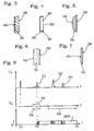
- FIGS. 3 to 7 different configurations of the reflector 36 are shown. All versions are based on the same idea. It should be avoided that a portion of the incident secondary beam, the passes through the reflection surface 38 and thus is not reflected directly on this, later once again to the reflective surface 38 and from this to one of the individual oscillators 20 to 28 can pass. In other words, so-called phantom signals should be prevented, which could simulate errors in the test object during the measurement.
- the reflector 36 is essentially an elongated plate.
- the reflection surface 38 opposite is a rear surface 46 which is densely covered with pyramidal damping bodies.
- the distance between two pyramidal damping bodies, which appear in the drawing as spikes, is smaller than the wavelength of the ultrasound in the material used. In this way, a reflection on the rear wall 46 is suppressed.
- the reflection surface 38 is formed by a thin foil, for example aluminum foil. It is held by a holder 48 which defines it at the edge. Behind the film is air. Ultrasound propagation practically does not take place in air. The portion of the acoustic energy from the sub-beam that has passed through the foil 50 is weakened so that phantom signals are suppressed.
- the reflector 36 is a rod with the cross section of a circular segment, as it is also in FIG. 1 is used.
- the rear wall 46 runs on a circular line.
- the reflector 36 is a rod of rectangular cross-section, due to the magnification, the upper and lower sides of the rectangle are in FIG. 6 not recognizable.
- the rod is made and filled with a material that takes a strong absorption of acoustic energy that has entered the volume of the rod.
- a material for such rods is particularly suitable so-called backing material, as it is used for the back of ultrasonic transducers for their damping.
- the material is often filled with grains of tungsten or other material particles. Reference is made to the already mentioned DE-book.
- the back wall 46 does not extend parallel to the reflection surface 38, but obliquely or to curve, such as FIG. 5 or pyramidal shape, such as FIG. 3 ,
- FIG. 7 a reflector 36, as in the embodiment according to FIG. 2 is used. He is similar to the training FIG. 3 However, now the back wall is wavy, with a wavelength smaller than the wavelength of the switched-on acoustic energy. Here, too, scattering takes place on the rear wall 46, so that essentially no acoustic energy which originates from the volume of the reflector 36 can escape through the reflecting surface 38.
- Embodiment after FIG. 5 have a rear wall 46, as the embodiments according to FIG. 3 or 7 show, also the volume can be filled with scattering bodies and made of a damping material, as this FIG. 6 exemplifies so-called backing body shows.
- FIG. 8 shows in the upper part of the diagram, the voltage waveform at the output of the receiver, ie the S / E stage 40. Shown is the receive voltage U R over the time t. At the time t1, one first recognizes the so-called transmission pulse. In the area around the time t2 comes a diffuse reflection of the main beam 30 with a low voltage value, this diffuse signal can not be used to trigger an electronic circuit, it is too imprecise. At time t2, the entry echo which has passed over the reflection surface 38 and therefore taken the indirect path, hits. There is a clear, sharp signal 51 which can be well used for triggering a subsequent electronic stage.
- a temporal expectation area 56 is drawn in which lies around the time t2. Within this expectation range 56 the entrance echo must fall. Otherwise, it is left unconsidered and there is no digitization.
- a threshold 58 is set which is at the value Us. Only signal voltages exceeding this threshold 58 are processed further. The threshold 58 is placed so that the diffuse reflections of the main beam are eliminated, but the clear reflection obtained by the indirect path is taken into account. From it a time-precise control signal, a so-called trigger signal can be obtained.
- the signal maintenance range 60 is located temporally. Only signals that fall within this range over time are processed. Later or earlier incoming signals are ignored.
- the lower part of FIG. 8 shows the information 200, 220, 240, etc., obtained after digitization.
- the digitization is started at the time t2, ie via the entrance echo, which is obtained indirectly.
- the digitization started at time t2 is terminated at time t3, which is the end point of the signal maintenance area 60.
- FIG. 9 shows eight different signals 200, 220, 240, etc. of the individual oscillators 20, 22, 24, etc., and in digitized form, corresponding to the lower field of FIG. 8 showing the digitized signal 200 from only a single oscillator, namely single oscillator 20.
- the digitized signals are stored in a memory 66.
- the digitization begins for all digitized signals at time t2. This time t2 may be different for each individual oscillator individually, it is the time of arrival of the indirect echo signal for the single oscillator.
- FIG. 10 shows the evaluation unit 44 in detail.
- the analog reception voltage UR is applied to an A / D converter 62. This receives via a line 64, a trigger or trigger signal from the control stage 42 at time t2.
- the digitized signal 200, 220, etc. is stored in a memory 66. Via a digital data processor 68, the evaluation of the stored digitized signals in any selection, order and composition and at any time. The result is output to a monitor 70 or other display unit.
- n is 200.
Landscapes
- Physics & Mathematics (AREA)
- Acoustics & Sound (AREA)
- Health & Medical Sciences (AREA)
- Life Sciences & Earth Sciences (AREA)
- Chemical & Material Sciences (AREA)
- Analytical Chemistry (AREA)
- Biochemistry (AREA)
- General Health & Medical Sciences (AREA)
- General Physics & Mathematics (AREA)
- Immunology (AREA)
- Pathology (AREA)
- Investigating Or Analyzing Materials By The Use Of Ultrasonic Waves (AREA)
Claims (10)
- Procédé de contrôle par ultrasons d'un objet à contrôler (32), dans lequel de l'ultrason est émis par un palpeur, atteint - via un chemin de couplage - ledit objet à contrôler (32), et, ensuite, au moins un signal d'écho (52, 54) de l'ultrason émis dedans est détecté par ledit palpeur, l'ultrason émis se propageant dans un champ sonore et autour d'un rayon central, ledit rayon central rencontrant la surface de l'objet à contrôler (32) non pas à angle droit, et entre ledit palpeur et ledit objet à contrôler (32) étant prévue une surface de réflexion (38) qui est située hors du rayon central, mais à l'intérieur du champ sonore et est disposée de manière à ce que la partie de l'ultrason émis, qui rencontre ladite surface de réflexion (38), rencontre la surface de l'objet à contrôler (32), après réflexion, pour l'essentiel à angle droit, retourne depuis là et soit utilisée en tant que signal (51) pour un début d'écho, caractérisé par le fait que ledit palpeur est un réseau linéaire à n transducteurs particuliers (22, 24...), qu'à chacun des transducteurs particuliers (22, 24...) est associée une propre surface de réflexion (38), que pour chacun des transducteurs particuliers (22, 24...) est généré un propre signal de début d'écho (51), que les signaux de réception (52, 54) reçus par chacun des transducteurs particuliers (22, 24...) sont numérisés et que cette numérisation est lancée individuellement pour chacun des transducteurs particuliers (22, 24...) avec le signal de début d'écho (52, 54) de ce transducteur particulier (22, 24...).
- Procédé selon la revendication 1, caractérisé par le fait que les signaux de réception numérisés (200, 220, ...) (données de réception) sont mémorisés dans une mémoire (66) et que, durant une évaluation, les signaux de réception numérisés (200, 220, ...) aussi bien de transducteurs particuliers (22, 24...) individuels que de combinaisons différentes de transducteurs particuliers (22, 24...) sont analysés quant à l'amplitude et au temps de parcours.
- Procédé selon la revendication 1, caractérisé par le fait que lesdits n transducteurs particuliers (22, 24...) sont commandés individuellement pour générer un signal individuel d'émission pour le transducteur particulier (22, 24...) respectif.
- Procédé selon la revendication 1, caractérisé par le fait que plusieurs, à savoir au moins deux transducteurs particuliers (22, 24...) sont interconnectés pour former un groupe et qu'un groupe est opéré comme un transducteur particulier (22, 24...) pour la durée de cette interconnexion.
- Procédé selon la revendication 1, caractérisé par le fait que l'ensemble des transducteurs particuliers (22, 24...) présentent la même distance par rapport à la surface dudit objet à contrôler (32) et que leurs rayons principaux (30) rencontrent la surface de l'objet à contrôler (32) avec le même angle d'incidence et que les surfaces de réflexion (38) des transducteurs particuliers (22, 24...) individuels sont dans le même arrangement géométrique par rapport au transducteur particulier (22, 24...), en particulier quant à la distance par rapport au rayon principal (30) et quant à l'angle par rapport au rayon principal (30), que dans tous les autres transducteurs particuliers (22, 24...).
- Procédé selon la revendication 1, caractérisé par le fait que les transducteurs particuliers (22, 24...) sont construits de manière identique entre eux.
- Procédé selon la revendication 1, caractérisé par le fait que les surfaces de réflexion (38) sont réalisées de manière identique, de préférence d'une seule pièce de façon continue.
- Procédé selon la revendication 1, caractérisé par le fait que les surfaces de réflexion (38) sont réalisées de manière à ce que de la matière se trouvant derrière la surface de réflexion (38) ou affaiblisse l'ultrason et/ou le dirige de telle sorte que la part de l'ultrason rencontrant ladite surface de réflexion (38), qui a pénétré dans la matière n'atteigne ni un transducteur particulier (22, 24...) ni l'objet à contrôler (32).
- Dispositif pour la mise en oeuvre du procédé selon la revendication 1, comprenant un palpeur avec une électronique associée de commande et d'évaluation, un chemin de couplage, un objet à contrôler (32) et - entre ledit palpeur et ledit objet à contrôler (32) - une surface de réflexion (38) qui forme un angle aigu avec un rayon marginal du champ sonore du palpeur et est disposée de manière à ce que le rayon marginal rencontre ladite surface de l'objet à contrôler (32) pour l'essentiel à angle droit, caractérisé par le fait que ledit palpeur est un réseau linéaire à n transducteurs particuliers (22, 24...), qu'à chacun des transducteurs particuliers (22, 24...) est associée une propre surface de réflexion (38), que ladite électronique d'évaluation comprend un convertisseur analogique-numérique (62) et une mémoire (66), que dans ladite mémoire (66) sont mémorisés les signaux de réception numérisés (200, 220, ...) des transducteurs particuliers (22, 24...) et que ladite électronique d'évaluation comprend une unité de déclenchement qui lance la numérisation d'un signal de réception (52, 54) en cas de présence du signal de début d'écho (52, 54) du transducteur particulier (22, 24...).
- Dispositif selon la revendication 9, caractérisé par le fait que de la matière se trouve derrière la surface de réflexion (38) et que cette matière est une matière absorbant le son pour l'ultrason utilisé et/ou est réalisée géométriquement de manière à ce que des réflexions à l'intérieur de la matière ne puissent pas sortir de la surface de réflexion (38) et atteindre le palpeur ou l'objet à contrôler (32).
Applications Claiming Priority (3)
| Application Number | Priority Date | Filing Date | Title |
|---|---|---|---|
| DE10151546 | 2001-10-23 | ||
| DE10151546A DE10151546A1 (de) | 2001-10-23 | 2001-10-23 | Verfahren und Vorrichtung zur Ultraschallprüfung mittels eines linearen Arrays und mit Echostart |
| PCT/DE2002/003889 WO2003038427A1 (fr) | 2001-10-23 | 2002-10-15 | Procede et dispositif de controle par ultrasons au moyen d'un reseau lineaire et d'un echostart |
Publications (3)
| Publication Number | Publication Date |
|---|---|
| EP1440310A1 EP1440310A1 (fr) | 2004-07-28 |
| EP1440310B1 true EP1440310B1 (fr) | 2011-11-30 |
| EP1440310B8 EP1440310B8 (fr) | 2012-03-14 |
Family
ID=7702981
Family Applications (1)
| Application Number | Title | Priority Date | Filing Date |
|---|---|---|---|
| EP02781136A Expired - Lifetime EP1440310B8 (fr) | 2001-10-23 | 2002-10-15 | Procede et dispositif de controle par ultrasons au moyen d'un reseau lineaire et d'un echostart |
Country Status (4)
| Country | Link |
|---|---|
| EP (1) | EP1440310B8 (fr) |
| AT (1) | ATE535802T1 (fr) |
| DE (1) | DE10151546A1 (fr) |
| WO (1) | WO2003038427A1 (fr) |
Families Citing this family (1)
| Publication number | Priority date | Publication date | Assignee | Title |
|---|---|---|---|---|
| DE102007014246B4 (de) * | 2007-03-24 | 2011-06-01 | Leuze Electronic Gmbh & Co Kg | Ultraschallsensor |
Family Cites Families (4)
| Publication number | Priority date | Publication date | Assignee | Title |
|---|---|---|---|---|
| US4022055A (en) * | 1974-12-02 | 1977-05-10 | Texaco Inc. | Pulse-echo method and system for testing wall thicknesses |
| FR2670583B1 (fr) * | 1990-12-13 | 1994-03-04 | Valtubes | Dispositif detecteur de defauts par ultra-sons dans des tubes metalliques et procede pour sa mise en óoeuvre. |
| DE19804298B4 (de) * | 1998-02-04 | 2006-12-07 | Krautkrämer GmbH & Co | Verfahren zur Ultraschallprüfung mit Echostart und Vorrichtung hierfür |
| FR2796153B1 (fr) * | 1999-07-09 | 2001-11-30 | Setval | Controle non destructif a capteurs ultrasonores repartis |
-
2001
- 2001-10-23 DE DE10151546A patent/DE10151546A1/de not_active Ceased
-
2002
- 2002-10-15 WO PCT/DE2002/003889 patent/WO2003038427A1/fr not_active Ceased
- 2002-10-15 AT AT02781136T patent/ATE535802T1/de active
- 2002-10-15 EP EP02781136A patent/EP1440310B8/fr not_active Expired - Lifetime
Also Published As
| Publication number | Publication date |
|---|---|
| ATE535802T1 (de) | 2011-12-15 |
| DE10151546A1 (de) | 2003-04-30 |
| EP1440310A1 (fr) | 2004-07-28 |
| WO2003038427A1 (fr) | 2003-05-08 |
| EP1440310B8 (fr) | 2012-03-14 |
Similar Documents
| Publication | Publication Date | Title |
|---|---|---|
| DE3751714T2 (de) | Verfahren und Apparatur zum Ultraschallnachweis von Rissen | |
| DE10248979B4 (de) | Multielement-Ultraschall-Transducer und Ultraschall-Prüfverfahren | |
| EP2032978B1 (fr) | Appareil de contrôle ultrasonore muni de têtes de contrôle à réseau | |
| EP1979739B1 (fr) | Procede d'examen non destructif d'une eprouvette dont au moins une region est constituee d'un materiau acoustiquement anisotrope | |
| DE102004059856B4 (de) | Verfahren zur zerstörungsfreien Untersuchung eines Prüfkörpers mittels Ultraschall | |
| DE2216264A1 (de) | Verfahren und Vorrichtung zur Materialprüfung mittels Ultraschall | |
| EP2335064B1 (fr) | Méthode par impulsion-écho au moyen d'un réseau de transducteurs et avec compensation thermique | |
| DE102005051781A1 (de) | Verfahren zur zerstörungsfreien Untersuchung eines Prüfkörpers mittels Ultraschall | |
| DE102008027228B4 (de) | Verfahren und Vorrichtung zur zerstörungsfreien Ultraschalluntersuchung eines Prüfstücks mit zueinander gewinkelten, ebenen Oberflächen | |
| DE102019106427B4 (de) | Wandler und Wandleranordnung für Ultraschall-Prüfkopfsysteme, Ultraschall-Prüfkopfsystem und Prüfverfahren | |
| DE102013004924B4 (de) | Bildgebungssystem und -verfahren | |
| DE102008027384A1 (de) | Verbesserte zerstörungsfreie Ultraschalluntersuchung mit Kopplungskontrolle | |
| DE1816255C3 (de) | Verfahren zur zerstörungsfreien Prüfung von Schweißnahten mittels Ultra schallenergie | |
| DE2238130C3 (de) | Verfahren zur Ermittlung und Kompensation von unterschiedlichen Schallschwächungseigenschaften bei der Ultraschall-Werkstoffprüfung | |
| DE3715914C2 (fr) | ||
| EP1440310B1 (fr) | Procede et dispositif de controle par ultrasons au moyen d'un reseau lineaire et d'un echostart | |
| DE102018119206B4 (de) | Verfahren zum Erfassen einer Geometrie eines Bereichs eines Gegenstandes mittels Ultraschall | |
| DE10259658A1 (de) | Verfahren zur Auswertung von Ultraschallsignalen | |
| DE2710403C2 (de) | Verfahren und Vorrichtung zur Ultraschallprüfung der Wandstärke von Rohren u.dgl. | |
| DE3241200A1 (de) | Ultraschallwandleranordnung | |
| DE102009040748B4 (de) | Vorrichtung zur zerstörungsfreien Prüfung von Schweißnähten in Werkstücken mittels Ultraschall | |
| EP0425765A1 (fr) | Procédé de détection des fissures par ultrasons | |
| DE2651001C3 (fr) | ||
| DE19957905A1 (de) | Verfahren und Vorrichtung zur zerstörungsfreien Prüfung von Schweißnähten mittels Ultraschall | |
| DE2923142C2 (de) | Ultraschallgeber zur Werkstoffprüfung in Tauchtechnik |
Legal Events
| Date | Code | Title | Description |
|---|---|---|---|
| PUAI | Public reference made under article 153(3) epc to a published international application that has entered the european phase |
Free format text: ORIGINAL CODE: 0009012 |
|
| 17P | Request for examination filed |
Effective date: 20040524 |
|
| AK | Designated contracting states |
Kind code of ref document: A1 Designated state(s): AT BE BG CH CY CZ DE DK EE ES FI FR GB GR IE IT LI LU MC NL PT SE SK TR |
|
| 17Q | First examination report despatched |
Effective date: 20100305 |
|
| GRAP | Despatch of communication of intention to grant a patent |
Free format text: ORIGINAL CODE: EPIDOSNIGR1 |
|
| GRAS | Grant fee paid |
Free format text: ORIGINAL CODE: EPIDOSNIGR3 |
|
| GRAA | (expected) grant |
Free format text: ORIGINAL CODE: 0009210 |
|
| AK | Designated contracting states |
Kind code of ref document: B1 Designated state(s): AT BE BG CH CY CZ DE DK EE ES FI FR GB GR IE IT LI LU MC NL PT SE SK TR |
|
| REG | Reference to a national code |
Ref country code: GB Ref legal event code: FG4D Free format text: NOT ENGLISH Ref country code: CH Ref legal event code: EP |
|
| RAP2 | Party data changed (patent owner data changed or rights of a patent transferred) |
Owner name: GE SENSING & INSPECTION TECHNOLOGIES GMBH |
|
| REG | Reference to a national code |
Ref country code: IE Ref legal event code: FG4D Free format text: LANGUAGE OF EP DOCUMENT: GERMAN |
|
| REG | Reference to a national code |
Ref country code: DE Ref legal event code: R096 Ref document number: 50215306 Country of ref document: DE Effective date: 20120126 |
|
| REG | Reference to a national code |
Ref country code: DE Ref legal event code: R082 Ref document number: 50215306 Country of ref document: DE Representative=s name: BAUER-VORBERG-KAYSER, DE Ref country code: DE Ref legal event code: R082 Ref document number: 50215306 Country of ref document: DE Representative=s name: PATENTANWAELTE BAUER VORBERG KAYSER PARTNERSCH, DE |
|
| REG | Reference to a national code |
Ref country code: NL Ref legal event code: VDEP Effective date: 20111130 |
|
| PG25 | Lapsed in a contracting state [announced via postgrant information from national office to epo] |
Ref country code: SE Free format text: LAPSE BECAUSE OF FAILURE TO SUBMIT A TRANSLATION OF THE DESCRIPTION OR TO PAY THE FEE WITHIN THE PRESCRIBED TIME-LIMIT Effective date: 20111130 Ref country code: GR Free format text: LAPSE BECAUSE OF FAILURE TO SUBMIT A TRANSLATION OF THE DESCRIPTION OR TO PAY THE FEE WITHIN THE PRESCRIBED TIME-LIMIT Effective date: 20120301 Ref country code: NL Free format text: LAPSE BECAUSE OF FAILURE TO SUBMIT A TRANSLATION OF THE DESCRIPTION OR TO PAY THE FEE WITHIN THE PRESCRIBED TIME-LIMIT Effective date: 20111130 Ref country code: PT Free format text: LAPSE BECAUSE OF FAILURE TO SUBMIT A TRANSLATION OF THE DESCRIPTION OR TO PAY THE FEE WITHIN THE PRESCRIBED TIME-LIMIT Effective date: 20120330 |
|
| REG | Reference to a national code |
Ref country code: IE Ref legal event code: FD4D |
|
| PG25 | Lapsed in a contracting state [announced via postgrant information from national office to epo] |
Ref country code: CY Free format text: LAPSE BECAUSE OF FAILURE TO SUBMIT A TRANSLATION OF THE DESCRIPTION OR TO PAY THE FEE WITHIN THE PRESCRIBED TIME-LIMIT Effective date: 20111130 |
|
| PG25 | Lapsed in a contracting state [announced via postgrant information from national office to epo] |
Ref country code: BG Free format text: LAPSE BECAUSE OF FAILURE TO SUBMIT A TRANSLATION OF THE DESCRIPTION OR TO PAY THE FEE WITHIN THE PRESCRIBED TIME-LIMIT Effective date: 20120229 Ref country code: SK Free format text: LAPSE BECAUSE OF FAILURE TO SUBMIT A TRANSLATION OF THE DESCRIPTION OR TO PAY THE FEE WITHIN THE PRESCRIBED TIME-LIMIT Effective date: 20111130 Ref country code: DK Free format text: LAPSE BECAUSE OF FAILURE TO SUBMIT A TRANSLATION OF THE DESCRIPTION OR TO PAY THE FEE WITHIN THE PRESCRIBED TIME-LIMIT Effective date: 20111130 Ref country code: IE Free format text: LAPSE BECAUSE OF FAILURE TO SUBMIT A TRANSLATION OF THE DESCRIPTION OR TO PAY THE FEE WITHIN THE PRESCRIBED TIME-LIMIT Effective date: 20111130 Ref country code: EE Free format text: LAPSE BECAUSE OF FAILURE TO SUBMIT A TRANSLATION OF THE DESCRIPTION OR TO PAY THE FEE WITHIN THE PRESCRIBED TIME-LIMIT Effective date: 20111130 Ref country code: CZ Free format text: LAPSE BECAUSE OF FAILURE TO SUBMIT A TRANSLATION OF THE DESCRIPTION OR TO PAY THE FEE WITHIN THE PRESCRIBED TIME-LIMIT Effective date: 20111130 |
|
| PLBE | No opposition filed within time limit |
Free format text: ORIGINAL CODE: 0009261 |
|
| STAA | Information on the status of an ep patent application or granted ep patent |
Free format text: STATUS: NO OPPOSITION FILED WITHIN TIME LIMIT |
|
| 26N | No opposition filed |
Effective date: 20120831 |
|
| REG | Reference to a national code |
Ref country code: DE Ref legal event code: R097 Ref document number: 50215306 Country of ref document: DE Effective date: 20120831 |
|
| BERE | Be: lapsed |
Owner name: PRAUSE, REINHARD Effective date: 20121031 Owner name: AGFA NDT G.M.B.H. Effective date: 20121031 |
|
| PG25 | Lapsed in a contracting state [announced via postgrant information from national office to epo] |
Ref country code: ES Free format text: LAPSE BECAUSE OF FAILURE TO SUBMIT A TRANSLATION OF THE DESCRIPTION OR TO PAY THE FEE WITHIN THE PRESCRIBED TIME-LIMIT Effective date: 20120311 |
|
| PG25 | Lapsed in a contracting state [announced via postgrant information from national office to epo] |
Ref country code: MC Free format text: LAPSE BECAUSE OF NON-PAYMENT OF DUE FEES Effective date: 20121031 |
|
| REG | Reference to a national code |
Ref country code: CH Ref legal event code: PL |
|
| PG25 | Lapsed in a contracting state [announced via postgrant information from national office to epo] |
Ref country code: FI Free format text: LAPSE BECAUSE OF FAILURE TO SUBMIT A TRANSLATION OF THE DESCRIPTION OR TO PAY THE FEE WITHIN THE PRESCRIBED TIME-LIMIT Effective date: 20111130 |
|
| PG25 | Lapsed in a contracting state [announced via postgrant information from national office to epo] |
Ref country code: CH Free format text: LAPSE BECAUSE OF NON-PAYMENT OF DUE FEES Effective date: 20121031 Ref country code: LI Free format text: LAPSE BECAUSE OF NON-PAYMENT OF DUE FEES Effective date: 20121031 Ref country code: BE Free format text: LAPSE BECAUSE OF NON-PAYMENT OF DUE FEES Effective date: 20121031 |
|
| REG | Reference to a national code |
Ref country code: AT Ref legal event code: MM01 Ref document number: 535802 Country of ref document: AT Kind code of ref document: T Effective date: 20121031 |
|
| PG25 | Lapsed in a contracting state [announced via postgrant information from national office to epo] |
Ref country code: AT Free format text: LAPSE BECAUSE OF NON-PAYMENT OF DUE FEES Effective date: 20121031 |
|
| PG25 | Lapsed in a contracting state [announced via postgrant information from national office to epo] |
Ref country code: TR Free format text: LAPSE BECAUSE OF FAILURE TO SUBMIT A TRANSLATION OF THE DESCRIPTION OR TO PAY THE FEE WITHIN THE PRESCRIBED TIME-LIMIT Effective date: 20111130 |
|
| PG25 | Lapsed in a contracting state [announced via postgrant information from national office to epo] |
Ref country code: LU Free format text: LAPSE BECAUSE OF NON-PAYMENT OF DUE FEES Effective date: 20121015 |
|
| PGFP | Annual fee paid to national office [announced via postgrant information from national office to epo] |
Ref country code: FR Payment date: 20141017 Year of fee payment: 13 Ref country code: DE Payment date: 20141029 Year of fee payment: 13 Ref country code: GB Payment date: 20141027 Year of fee payment: 13 |
|
| PGFP | Annual fee paid to national office [announced via postgrant information from national office to epo] |
Ref country code: IT Payment date: 20141027 Year of fee payment: 13 |
|
| REG | Reference to a national code |
Ref country code: DE Ref legal event code: R119 Ref document number: 50215306 Country of ref document: DE |
|
| GBPC | Gb: european patent ceased through non-payment of renewal fee |
Effective date: 20151015 |
|
| PG25 | Lapsed in a contracting state [announced via postgrant information from national office to epo] |
Ref country code: IT Free format text: LAPSE BECAUSE OF NON-PAYMENT OF DUE FEES Effective date: 20151015 Ref country code: DE Free format text: LAPSE BECAUSE OF NON-PAYMENT OF DUE FEES Effective date: 20160503 Ref country code: GB Free format text: LAPSE BECAUSE OF NON-PAYMENT OF DUE FEES Effective date: 20151015 |
|
| REG | Reference to a national code |
Ref country code: FR Ref legal event code: ST Effective date: 20160630 |
|
| PG25 | Lapsed in a contracting state [announced via postgrant information from national office to epo] |
Ref country code: FR Free format text: LAPSE BECAUSE OF NON-PAYMENT OF DUE FEES Effective date: 20151102 |