EP1440754A1 - Outil de coupe au carbure cemente revetu, comprenant une couche de revetement dure presentant d'excellentes proprietes de resistance a l'usure dans l'usinage a grande vitesse - Google Patents
Outil de coupe au carbure cemente revetu, comprenant une couche de revetement dure presentant d'excellentes proprietes de resistance a l'usure dans l'usinage a grande vitesse Download PDFInfo
- Publication number
- EP1440754A1 EP1440754A1 EP02777977A EP02777977A EP1440754A1 EP 1440754 A1 EP1440754 A1 EP 1440754A1 EP 02777977 A EP02777977 A EP 02777977A EP 02777977 A EP02777977 A EP 02777977A EP 1440754 A1 EP1440754 A1 EP 1440754A1
- Authority
- EP
- European Patent Office
- Prior art keywords
- cemented carbide
- layer
- compound layer
- hard coating
- ranges
- Prior art date
- Legal status (The legal status is an assumption and is not a legal conclusion. Google has not performed a legal analysis and makes no representation as to the accuracy of the status listed.)
- Withdrawn
Links
Images


Classifications
-
- B—PERFORMING OPERATIONS; TRANSPORTING
- B23—MACHINE TOOLS; METAL-WORKING NOT OTHERWISE PROVIDED FOR
- B23B—TURNING; BORING
- B23B27/00—Tools for turning or boring machines; Tools of a similar kind in general; Accessories therefor
- B23B27/14—Cutting tools of which the bits or tips or cutting inserts are of special material
-
- C—CHEMISTRY; METALLURGY
- C23—COATING METALLIC MATERIAL; COATING MATERIAL WITH METALLIC MATERIAL; CHEMICAL SURFACE TREATMENT; DIFFUSION TREATMENT OF METALLIC MATERIAL; COATING BY VACUUM EVAPORATION, BY SPUTTERING, BY ION IMPLANTATION OR BY CHEMICAL VAPOUR DEPOSITION, IN GENERAL; INHIBITING CORROSION OF METALLIC MATERIAL OR INCRUSTATION IN GENERAL
- C23C—COATING METALLIC MATERIAL; COATING MATERIAL WITH METALLIC MATERIAL; SURFACE TREATMENT OF METALLIC MATERIAL BY DIFFUSION INTO THE SURFACE, BY CHEMICAL CONVERSION OR SUBSTITUTION; COATING BY VACUUM EVAPORATION, BY SPUTTERING, BY ION IMPLANTATION OR BY CHEMICAL VAPOUR DEPOSITION, IN GENERAL
- C23C30/00—Coating with metallic material characterised only by the composition of the metallic material, i.e. not characterised by the coating process
- C23C30/005—Coating with metallic material characterised only by the composition of the metallic material, i.e. not characterised by the coating process on hard metal substrates
-
- C—CHEMISTRY; METALLURGY
- C23—COATING METALLIC MATERIAL; COATING MATERIAL WITH METALLIC MATERIAL; CHEMICAL SURFACE TREATMENT; DIFFUSION TREATMENT OF METALLIC MATERIAL; COATING BY VACUUM EVAPORATION, BY SPUTTERING, BY ION IMPLANTATION OR BY CHEMICAL VAPOUR DEPOSITION, IN GENERAL; INHIBITING CORROSION OF METALLIC MATERIAL OR INCRUSTATION IN GENERAL
- C23C—COATING METALLIC MATERIAL; COATING MATERIAL WITH METALLIC MATERIAL; SURFACE TREATMENT OF METALLIC MATERIAL BY DIFFUSION INTO THE SURFACE, BY CHEMICAL CONVERSION OR SUBSTITUTION; COATING BY VACUUM EVAPORATION, BY SPUTTERING, BY ION IMPLANTATION OR BY CHEMICAL VAPOUR DEPOSITION, IN GENERAL
- C23C14/00—Coating by vacuum evaporation, by sputtering or by ion implantation of the coating forming material
- C23C14/06—Coating by vacuum evaporation, by sputtering or by ion implantation of the coating forming material characterised by the coating material
- C23C14/0641—Nitrides
-
- C—CHEMISTRY; METALLURGY
- C23—COATING METALLIC MATERIAL; COATING MATERIAL WITH METALLIC MATERIAL; CHEMICAL SURFACE TREATMENT; DIFFUSION TREATMENT OF METALLIC MATERIAL; COATING BY VACUUM EVAPORATION, BY SPUTTERING, BY ION IMPLANTATION OR BY CHEMICAL VAPOUR DEPOSITION, IN GENERAL; INHIBITING CORROSION OF METALLIC MATERIAL OR INCRUSTATION IN GENERAL
- C23C—COATING METALLIC MATERIAL; COATING MATERIAL WITH METALLIC MATERIAL; SURFACE TREATMENT OF METALLIC MATERIAL BY DIFFUSION INTO THE SURFACE, BY CHEMICAL CONVERSION OR SUBSTITUTION; COATING BY VACUUM EVAPORATION, BY SPUTTERING, BY ION IMPLANTATION OR BY CHEMICAL VAPOUR DEPOSITION, IN GENERAL
- C23C14/00—Coating by vacuum evaporation, by sputtering or by ion implantation of the coating forming material
- C23C14/06—Coating by vacuum evaporation, by sputtering or by ion implantation of the coating forming material characterised by the coating material
- C23C14/0664—Carbonitrides
-
- Y—GENERAL TAGGING OF NEW TECHNOLOGICAL DEVELOPMENTS; GENERAL TAGGING OF CROSS-SECTIONAL TECHNOLOGIES SPANNING OVER SEVERAL SECTIONS OF THE IPC; TECHNICAL SUBJECTS COVERED BY FORMER USPC CROSS-REFERENCE ART COLLECTIONS [XRACs] AND DIGESTS
- Y10—TECHNICAL SUBJECTS COVERED BY FORMER USPC
- Y10T—TECHNICAL SUBJECTS COVERED BY FORMER US CLASSIFICATION
- Y10T407/00—Cutters, for shaping
- Y10T407/27—Cutters, for shaping comprising tool of specific chemical composition
-
- Y—GENERAL TAGGING OF NEW TECHNOLOGICAL DEVELOPMENTS; GENERAL TAGGING OF CROSS-SECTIONAL TECHNOLOGIES SPANNING OVER SEVERAL SECTIONS OF THE IPC; TECHNICAL SUBJECTS COVERED BY FORMER USPC CROSS-REFERENCE ART COLLECTIONS [XRACs] AND DIGESTS
- Y10—TECHNICAL SUBJECTS COVERED BY FORMER USPC
- Y10T—TECHNICAL SUBJECTS COVERED BY FORMER US CLASSIFICATION
- Y10T428/00—Stock material or miscellaneous articles
- Y10T428/24—Structurally defined web or sheet [e.g., overall dimension, etc.]
- Y10T428/24942—Structurally defined web or sheet [e.g., overall dimension, etc.] including components having same physical characteristic in differing degree
- Y10T428/2495—Thickness [relative or absolute]
- Y10T428/24967—Absolute thicknesses specified
- Y10T428/24975—No layer or component greater than 5 mils thick
-
- Y—GENERAL TAGGING OF NEW TECHNOLOGICAL DEVELOPMENTS; GENERAL TAGGING OF CROSS-SECTIONAL TECHNOLOGIES SPANNING OVER SEVERAL SECTIONS OF THE IPC; TECHNICAL SUBJECTS COVERED BY FORMER USPC CROSS-REFERENCE ART COLLECTIONS [XRACs] AND DIGESTS
- Y10—TECHNICAL SUBJECTS COVERED BY FORMER USPC
- Y10T—TECHNICAL SUBJECTS COVERED BY FORMER US CLASSIFICATION
- Y10T428/00—Stock material or miscellaneous articles
- Y10T428/26—Web or sheet containing structurally defined element or component, the element or component having a specified physical dimension
- Y10T428/263—Coating layer not in excess of 5 mils thick or equivalent
- Y10T428/264—Up to 3 mils
- Y10T428/265—1 mil or less
Definitions
- the present invention relates to a cemented carbide cutting tool with a surface layer (hereinafter referred to as coated cemented carbide tool) in which a hard coating layer has excellent heat resistance so as to show high wear resistance even when it is applied to a high-speed cutting operation on various steels and cast irons accompanied by high heat generation.
- Throw-away type cutting inserts are used in various cutting operations such as turning or planing of a workpiece made of various steels or cast irons while being exchangably attached on a tip of a cutting tool. Twist drills and micro drills that are used for a drilling or boring of the above-mentioned workpiece are also well known.
- solid type end-milling cutters used in various operations such as face milling, groove milling, and shoulder milling of the workpiece are widely used.
- throw-away type end-milling cutters for cutting operation are also known as cutting tools to which the throw-away cutting inserts are exchangably attached.
- a coated cemented carbide tool is well known in which a hard coating layer with an average thickness of 2 to 15 ⁇ m consisting of a layer of Ti-Al nitride compound (hereinafter referred to as (Ti, Al)N) is deposited on a substrate made of tungsten carbide (hereinafter referred to as WC) based cemented carbide or titanium carbonitride (hereinafter referred to as TiCN) based cermet (hereinafter the substrate is generically referred to as cemented carbide substrate) by using physical vapor deposition.
- WC tungsten carbide
- TiCN titanium carbonitride
- composition formula of the Ti-Al nitride compound layer is expressed by (Ti 1-Z Al Z )N, wherein Z ranges from 0.45 to 0.65 by atomic ratio. It is also well known that such coated cemented carbide tool is preferably used for continuous cutting operation as well as interrupted cutting operation on various steels or cast irons.
- the above-mentioned coated cemented carbide tool is made by vapor deposition of the hard coating layer consisting of the (Ti, Al)N layer on the surface of the cemented carbide substrate as follows: First, the cemented carbide substrate is set into a chamber of an arc ion plating system, which is one of the physical vapor deposition processes, having an arrangement as shown in FIG.
- the (Ti, Al)N layer is then coated under the following conditions, that is, for example, at first, in a condition of about 0.5 Pa and 500 oC achieved by a heater inside the chamber, an arc discharge is generated between an anode and a cathode (an evaporation source) in which an Ti-Al alloy having predetermined composition is set, by loading electrical potential of 35V and electrical current of 90A, while nitrogen gas is introduced as a reaction gas into the chamber, and the bias DC voltage of, for example -200V, is applied to the substrate.
- a cathode an evaporation source
- Another coated cemented carbide tool is also well known as a cutting tool in a similar fashion to the above described tool, wherein a hard coating layer with an average thickness of 2 to 10 ⁇ m consisting of a layer of Al-Ti-Si nitride compound (hereinafter referred to as (AI, Ti, Si)N) is deposited on a substrate made of WC based cemented carbide or TiCN based cermet by using physical vapor deposition.
- the composition formula of the Al-Ti-Si nitride compound layer is expressed by (Al 1-(A+B) Ti A Si B )N, wherein A ranges from 0.35 to 0.55 and B ranges from 0.05 to 0.20 by atomic ratio.
- such coated cemented carbide tool is preferably used for continuous cutting operation as well as interrupted cutting operation on various steels or cast irons.
- the above-mentioned coated cemented carbide tool is made by vapor deposition of the hard coating layer consisting of the (Al, Ti, Si)N layer on the surface of the cemented carbide substrate as follows: First, the cemented carbide substrate is set into a chamber of an arc ion plating system, which is one of the physical vapor deposition processes, having an arrangement as shown in FIG.
- the (Al, Ti, Si)N layer is then coated under the following conditions, that is, for example, at first, in a condition of about 450 oC achieved by a heater inside the chamber, an arc discharge is generated between an anode and a cathode (an evaporation source) in which an Al-Ti-Si alloy having predetermined composition is set, by loading electrical potential of 40V and electrical current of 130A, while nitrogen gas is introduced as a reaction gas into the chamber up to 2 Pa, and the bias DC voltage of, for example, -50V, is applied to the substrate.
- a cathode an evaporation source
- cutting operation apparatuses tend to have significantly high performance on one hand, and it is strongly demanded that cutting operations be performed with less power and less energy as well as low cost on the other hand. Therefore, cutting operations tend to be performed at high speed.
- various kinds of coated cutting tools conventionally proposed as long as they are used in cutting operations under the usual cutting conditions, they have almost no problem. However, once they are used in high speed cutting operations accompanied by high heat generation, their operation lifetime becomes shorter due to accelerated abrasion of the hard coating layer.
- the present invention was conceived based on the above research results, and the present invention provides a coated cutting tool made of cemented carbide in which a hard coating layer has excellent wear resistance in high-speed cutting operations, wherein:
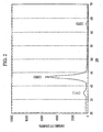
- the Ti-Al carbonitride compound layer is preferably a layer which exhibits an X-ray diffraction pattern having a peak found at a (200) plane with FWHM of not more than 0.6 degrees in 2 ⁇ measured by Cu K a radiation using an X-ray diffractometer
- the layer of Ti-Al nitride compound is also preferably a layer which exhibits an X-ray diffraction pattern having a peak found at a (200) plane with FWHM of not more than 0.6 degrees in 2 ⁇ measured by Cu K a radiation using an X-ray diffractometer.
- the aluminum (Al) component in the (Ti, Al)NC layer plays an important role in defining a (200) plane of this layer to be aligned parallel to the face and the flank of the cutting edge; if the Al ratio is less than 0.05 by atomic ratio, the degree of the alignment of the crystal in the (200) plane is not sufficiently high, and on the other hand, if the Al ratio is more than 0.20, the degree of crystallinity is decreased so that it becomes difficult to adjust FWHM of the peak at the (200) plane to a width of not more than 0.6 degrees in 2 ⁇ ; therefore, the ratio (X-value) was set from 0.05 to 0.20.
- the carbon (C) component in the (Ti, Al)NC layer improves adhesion for both the cemented carbide substrate surface and the hard coating layer; if the C ratio is less than 0.01 by atomic ratio, the desired effect to improve the adhesion cannot be obtained anymore; and on the other hand, if the C ratio is greater than 0.15, the crystal orientation is so disordered that it becomes difficult to align the crystal orientation in the (200) plane in a high degree; therefore, the ratio (Y-value) was set from 0.01 to 0.15.
- the average thickness of the crystal orientation hysteresis layer is less than 0.05 ⁇ m, the hysteresis effect to align the crystal orientation, in which the texture or alignment of the (Ti, Al)NC layer to the (200) plane in a high degree is transferred to the hard coating layer, is not fully used; and the cemented carbide substrate surface and the hard coating layer are not sufficiently adhered; and on the other hand, in the case in which the average thickness of the crystal orientation hysteresis layer is up to 0.5 ⁇ m, the hysteresis effect to align the crystal orientation and the effect to improve the adhesion are fully achieved; therefore the average thickness of the layer was set to from 0.05 to 0.5 ⁇ m.
- the Al component is contained in the (Ti, Al)N layer in order to increase thermal resistance and hardness of the TiN layer having high tenacity and so improve wear resistance thereof; if the ratio of Al to the sum of Al and Ti (i.e., atomic ratio of Al) is less than 0.45, the desired effect to improve the wear resistance cannot be obtained anymore; and on the other hand, if the ratio of Al is more than 0.65, the cutting edge tends to easily chip (small chipping); therefore, the ratio was set from 0.45 to 0.65.
- the average thickness of the hard coating layer is less than 2 ⁇ m, desired wear resistance cannot be obtained; and the other hand, if the average thickness is more than 15 ⁇ m, the cutting edge tends to easily chip; therefore, the average thickness was set to from 2 to 15 ⁇ m.
- a value of not more than 0.6 degrees (2 ⁇ ) for FWHM of the peak at the (200) plane in the X-ray diffraction pattern was chosen on the basis of the experimental result: This is because, in the case of FWHM of not more than 0.6 degrees, the hard coating layer has excellent wear resistance especially in high-speed cutting operation; and on the other hand, in the case of FWHM of more than 0.6 degrees or the lowered degree of the crystallinity in the (200) plane, desired wear resistance cannot be achieved anymore.
- the Ti-Al carbonitride compound layer is preferably a layer which exhibits an X-ray diffraction pattern having a peak found at a (200) plane with FWHM of not more than 0.6 degrees in 2 ⁇ measured by Cu K a radiation using an X-ray diffractometer
- the Al-Ti-Si nitride compound layer is also preferably a layer which exhibits an X-ray diffraction pattern having a peak found at a (200) plane with FWHM of not more than 0.6 degrees in 2 ⁇ measured by Cu K a radiation using an X-ray diffractometer.
- the aluminum (Al) component in the (Ti, Al)NC layer plays an important role in defining the (200) plane of the layer to be aligned parallel to the face and the flank of the cutting edge; if the ratio of Al to the sum of Al and Ti (i.e., atomic ratio of Al) is less than 0.01, the degree of the alignment of the crystal in the (200) plane is not sufficiently high, and on the other hand, if the Al ratio is more than 0.15, the degree of crystallinity is decreased so that it becomes difficult to adjust FWHM of the peak at the (200) plane to a width of not more than 0.6 degrees in 2 ⁇ ; therefore, the ratio (X-value) was set from 0.01 to 0.15.
- the C component in the (Ti, Al)NC layer improves adhesion for both the cemented carbide substrate surface and the hard coating layer; if the C ratio is less than 0.01 by atomic ratio, a desired effect to improve the adhesion cannot be obtained anymore; and on the other hand, if the C ratio is greater than 0.15, the crystal orientation is so disordered that it becomes difficult to align crystal orientation in the (200) plane in a high degree; therefore, the ratio (Y-value) was set from 0.01 to 0.15.
- the average thickness of the crystal orientation hysteresis layer is less than 0.05 ⁇ m, the hysteresis effect to align the crystal orientation, in which the texture or alignment of the (Ti, Al)NC layer to the (200) plane in a high degree is transferred to the hard coating layer, is not fully used; and on the other hand, in the case in which the average thickness of the crystal orientation hysteresis layer is up to 0.5 ⁇ m, the hysteresis effect to align the crystal orientation is fully achieved; therefore the average thickness of the layer was set to from 0.05 to 0.5 ⁇ m.
- the Ti component in the (Al, Ti, Si)N layer increases strength and toughness of the layer itself; if the ratio of Ti to the sum of Ti, Al and Si (i.e., atomic ratio of Ti) is less than 0.35, the effect increasing strength and toughness is not obtained as one desires; and the other hand, if the ratio is more than 0.55, wear resistance of the layer is decreased; therefore, the ratio was set to from 0.35 to 0.55.
- the Si component in the (Al, Ti, Si)N layer improves heat resistance and hardness at high temperature of the layer so that wear resistance of the layer is affected to be improved; if the ratio of Si to the sum of Si, Al and Ti (i.e., atomic ratio of Si) is less than 0.05, the effect improving wear resistance is not obtained as one desires; and the other hand, if the ratio is more than 0.20, strength and toughness are decreased and the cutting edge tends to easily chip; therefore, the ratio was set from 0.05 to 0.20.
- the average thickness of the hard coating layer is less than 2 ⁇ m, desired wear resistance cannot be achieved; and the other hand, if the average thickness is more than 10 ⁇ m, the cutting edge tends to easily chip; therefore, the average thickness was set to from 2 to 10 ⁇ m.
- a value of not more than 0.6 degrees (2 ⁇ ) for FWHM of the peak at the (200) plane in the X-ray diffraction pattern was chosen on the basis of the experimental result: This is because, in the case of FWHM of not more than 0.6 degrees, the hard coating layer has excellent wear resistance especially in high-speed cutting operation; and on the other hand, in the case of FWHM of more than 0.6 degrees or the lowered degree of the crystallinity in the (200) plane, desired wear resistance cannot be achieved anymore.
- Ingredient powders i.e., WC powder, TiC powder, ZrC powder, VC powder, TaC powder, NbC powder, Cr 3 C 2 powder, TiN powder, TaN powder, and Co powder, all of which have an average grain size in a range from 1 to 3 ⁇ m, were prepared and mixed in accordance with compounding ratios as presented in TABLE 1.
- the ingredient powders were mixed under wet conditions using a ball mill for 72 hours, were dried, and were compacted under pressure of 100 MPa so as to form a green compact.
- the green compact was held in a vacuum (pressure of 6 Pa) at a predetermined temperature of 1400 oC for 1 hour so as to be sintered.
- the ingredient powders were mixed under wet conditions using a ball mill for 24 hours, were dried, and were compacted under pressure of 100 MPa so as to form a green compact.
- the green compact was held in a nitrogen atmosphere (pressure of 2 kPa) at a predetermined temperature of 1500 oC for 1 hour so as to be sintered.
- these cemented carbide substrates A1 - A10 and B1 - B6 were subjected to ultrasonic cleaning in an acetone solvent, were dried, and set in an ordinary arc ion plating apparatus as shown in FIG. 5, respectively.
- the Ti-Al alloys for the hard coating layer and the Ti-Al alloys for the crystal orientation hysteresis layer having various compositions were set to form the cathode (evaporation source), and the inside of the apparatus is evacuated to keep 0.5 Pa and heated to 500 oC by the heater. Then, Ar was introduced in the apparatus to make the Ar atmosphere of 10 Pa.
- the DC bias voltage of -800V was applied to the cemented carbide substrate, and the surface of the substrate was cleaned by Ar bombardment.
- the bias voltage applied to the above-mentioned substrate was lowered to -70 V, and the arc discharge was generated between the above-mentioned cathode (Ti-Al alloy for the crystal orientation hysteresis layer) and the anode.
- the crystal orientation hysteresis layer (the (Ti, Al)NC layer) having the designated composition and thickness, which is shown in TABLES 3 and 4, was formed on the surface of the cemented carbide substrates A1 - A10 and B1 - B6, respectively.
- conventional throwaway type cutting inserts made of cemented carbide with surface coating 1 - 20 (hereinafter referred to as a conventional coated cemented carbide insert) as conventional coated cemented carbide tools were made as control samples as presented in TABLES 5 and 6, which are configured as with the inserts of the present invention excepting that the crystal orientation hysteresis layer ((Ti, Al)NC layer) is not formed.
- coated cemented carbide inserts of the present invention 1 - 20 and the conventional coated cemented carbide inserts 1 - 20 were subjected to a high-speed, dry, turning operation test, by screw setting these inserts at the top of the cutting tool made of a tool steel.
- the detailed test conditions were set as follows:
- each substrate has dimensions, i.e., the diameter and the length, of the part of the cutting edge of 6 mm x 13 mm, 10 mm x 22 mm, and 20 mm x 45 mm, respectively, as presented in TABLE 9.
- these cemented carbide substrates (end mills) a - h were subjected to ultrasonic cleaning in an acetone solvent, were dried, and set in an ordinary arc ion plating apparatus as shown in FIG. 5, respectively.
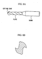
- end mill made of cemented carbide with surface coating of the present invention 1 - 8 (hereinafter referred to as a coated cemented carbide end mill of the present invention) having a geometrical configuration as shown in FIG. 7A as a perspective view and in FIG. 7B as a cross-sectional view were manufactured as coated cemented carbide tools of the present invention.
- conventional end mills made of cemented carbide with surface coating 1 - 8 (hereinafter referred as a conventional coated cemented carbide end mill) as conventional coated cemented carbide tools were made as control samples, as presented in TABLE 11, which are configured as with the end mills of the present invention excepting that the crystal orientation hysteresis layer ((Ti, Al)NC layer) is not formed.
- coated cemented carbide end mills of the present invention 1 - 8 and the conventional coated cemented carbide end mills 1 - 8 were subjected to a high-speed, dry, groove milling operation test.
- the detailed test conditions were set as follows:
- these cemented carbide substrates (twist drills) a' - h' were subjected to ultrasonic cleaning in an acetone solvent for the surface, were dried, and set in an ordinary arc ion plating apparatus as shown in FIG. 5, respectively.
- the crystal orientation hysteresis layer (the (Ti, Al)NC layer) and the hard coating layer ((Ti, Al)N layer) having the designated composition and thickness, which are presented in TABLE 12, were formed on the surface of the cemented carbide substrates by vapor deposition under the same condition as for Example 1, respectively.
- drills made of cemented carbide with surface coating of the present invention 1 - 8 (hereinafter referred to as a coated cemented carbide drill of the present invention) having a geometrical configuration as shown in FIG 8A as a perspective view and in FIG. 8B as a cross-sectional view were manufactured as coated cemented carbide tools of the present invention.
- conventional drills made of cemented carbide with surface coatings 1 - 8 (hereinafter referred as a conventional coated cemented carbide drill) as conventional coated cemented carbide tools were made as control samples, as presented in TABLE 13, which are configured as with the drills of the present invention excepting that the crystal orientation hysteresis layer ((Ti, Al)NC layer) is not formed.
- coated cemented carbide drills of the present invention 1 - 8 and the conventional coated cemented carbide drills 1 - 8 were subjected to a high-speed, wet, boring operation test in which a blind hole with 2.5 times the diameter of the drill-diameter was bored.
- the detailed test conditions were set as follows:
- compositions of the above-mentioned layers i.e., the crystal orientation hysteresis layer ((Ti, Al)NC layer) and the hard coating layer ((Ti, Al)N layer) on the coated cemented carbide inserts of the present invention 1 - 20, the coated cemented carbide end mills of the present invention 1 - 8 and the coated cemented carbide drills of the present invention 1 - 8 as the coated cemented carbide tools of the present invention, as well as the hard coating layer ((Ti, Al)N layer) on the conventional coated cemented carbide inserts 1 - 20, the conventional coated cemented carbide end mills 1 - 8, and the conventional coated cemented carbide drills 1 - 8 as the conventional coated cemented carbide tools, were measured in the thickness direction at the center area by using Auger Electron Spectral analysis equipment. The results of these measurements indicated that the composition of the layers was substantially the same as the designated value.
- the layers formed on the coated cemented carbide tools of the present invention and the conventional coated cemented carbide tools were inspected at the face and/or the flank of the cutting edge using an X-ray diffractometer. Through these inspections, FWHM of the peak at the (200) plane in the X-ray diffraction pattern was determined (here, when it was difficult to measure the tools itself, the sample pieces for measurement, which were set in the arc ion plating apparatus at the time of manufacturing the tools, were inspected and the X-ray diffraction pattern thereof was used to determine FWHM of the peak). These results are shown in TABLES 3 - 6 and TABLES 10 - 13.
- the coated cemented carbide tool of the present invention on which the hard coating layer having a peak of a narrow FWHM at the (200) plane due to the existence of the crystal orientation hysteresis layer and so having excellent heat resistance (i.e., resistance to oxidation and hardness at high temperature) exhibits an excellent wear resistance even in cutting operations not only of steels but also of cast irons accompanied by high heat generation: This is because both of the increase of the heat resistance and the improvement of the adhesion between the hard coating layer and the cemented carbide substrate surface due to the C component in the crystal orientation hysteresis layer provide a synergetic effect; As opposed to this, with regard to the conventional coated cemented carbide tool in which the degree of crystallinity at the (200) plane of the hard coating layer is low, abrasion proceeds rapidly and the operating life reaches an end in a short time when it is used in high-speed cutting operation accompanied by high heat generation.
- the coated cemented carbide tool according to the first embodiment has an excellent wear resistance even in high-speed cutting operations on various steels and cast irons, and exhibits outstanding ability for cutting so that it sufficiently meets the requirements that cutting apparatus should have high performance, and that cutting operations should be performed with less power, less energy and low cost.
- Ingredient powders i.e., WC powder, TiC powder, ZrC powder, VC powder, TaC powder, NbC powder, Cr 3 C 2 powder, TiN powder, TaN powder, and Co powder, all of which have an average grain size in a range from 1 to 3 ⁇ m, were prepared and mixed in accordance with compounding ratios as presented in TABLE 14.
- the ingredient powders were mixed under wet conditions using a ball mill for 72 hours, were dried, and were compacted under pressure of 100 MPa so as to form a green compact.
- the green compact was held in a vacuum (pressure of 6 Pa) at a predetermined temperature of 1400 oC for 1 hour so as to be sintered.
- the ingredient powders were mixed under wet conditions using a ball mill for 24 hours, were dried, and were compacted under pressure of 100 MPa so as to form a green compact.
- the green compact was held in a nitrogen atmosphere (pressure of 2 kPa) at a predetermined temperature of 1500 oC for 1 hour so as to be sintered.
- these cemented carbide substrates A1 - A10 and B1 - B6 were subjected to ultrasonic cleaning in an acetone solvent, were dried, and set in an ordinary arc ion plating apparatus as shown in FIG. 5, respectively.
- the Al-Ti-Si alloys for the hard coating layer and the Ti-Al alloys for the crystal orientation hysteresis layer having various compositions were set to form the cathode (evaporation source), and the inside of the apparatus is evacuated to keep 0.5 Pa and heated to 500 °C by the heater.
- Ar was introduced in the apparatus to make the Ar atmosphere of 1.3 Pa.
- the DC bias voltage of -800V was applied to the cemented carbide substrate, and the surface of the substrate was cleaned by Ar bombardment.
- the bias voltage applied to the above-mentioned substrate was lowered to -70 V, and the arc discharge was generated between the above-mentioned cathode (Ti-Al alloy for the crystal orientation hysteresis layer) and the anode.
- the crystal orientation hysteresis layer (the (Ti, Al)NC layer) having the designated composition and thickness, which is shown in TABLES 16 and 17, was formed on the surface of the cemented carbide substrates A1 - A10 and B1 - B6, respectively.
- conventional throwaway type inserts made of cemented carbide with surface coating 1 - 20 (hereinafter referred as a conventional coated cemented carbide insert) as conventional coated cemented carbide tools were made as control samples as presented in TABLES 18 and 19, which are configured as with the inserts of the present invention excepting that the crystal orientation hysteresis layer ((Ti, Al)NC layer) is not formed.
- coated cemented carbide inserts of the present invention 1 - 20 and the conventional coated cemented carbide inserts 1 - 20 were subjected to a high-speed, dry, turning operation test, by screw setting these inserts at the top of the cutting tool made of a tool steel.
- the detailed test conditions were set as follows:
- each substrate has dimensions, i.e., the diameter and the length, of the part of the cutting edge of 6 mm x 13 mm, 10 mm x 22 mm, and 20 mm x 45 mm, were respectively, as presented in TABLE 21.
- these cemented carbide substrates (end mills) a - h were subjected to ultrasonic cleaning in an acetone solvent, were dried, and set in an ordinary arc ion plating apparatus as shown in FIG. 5, respectively.
- the crystal orientation hysteresis layer (the (Ti, Al)NC layer) and the hard coating layer ((Al, Ti, Si)N layer) having the designated composition and thickness, which are presented in TABLE 22, were formed on the surface of the cemented carbide substrates by vapor deposition under the same condition as for Example 4, respectively.
- end mill made of cemented carbide with surface coating of the present invention 1 - 8 (hereinafter referred to as a coated cemented carbide end mill of the present invention) having a geometrical configuration as shown in FIG. 7A as a perspective view and in FIG. 7B as a cross-sectional view were manufactured as coated cemented carbide tools of the present invention.
- conventional end mills made of cemented carbide with surface coatings 1 - 8 (hereinafter referred as a conventional coated cemented carbide end mill) as conventional coated cemented carbide tools were made as control samples, as presented in TABLE 23, which are configured as with the end mills of the present invention excepting that the crystal orientation hysteresis layer ((Ti, Al)NC layer) is not formed.
- coated cemented carbide end mills of the present invention 1 - 8 and the conventional coated cemented carbide end mills 1 - 8 were subjected to a high-speed, dry, groove milling operation test.
- the detailed test conditions were set as follows:
- the three types of sintered round rod each having a diameter of 8 mm (for cemented carbide substrates a -c), 13 mm (for cemented carbide substrates d - f), and 26 mm (for cemented carbide substrates g, h), respectively, which were made through the process described in Example 5 were used again and further subjected to a grinding work so that cemented carbide substrates (twist drills) from “a' " to "h' " were made in which each substrate has dimensions, i.e., the diameter and the length, of 4 mm x 13 mm (cemented carbide substrates a' - c'), 8 mm x 22 mm (cemented carbide substrate d' - f'), and 16 mm x 45 mm (cemented carbide substrates g', h'), respectively.
- these cemented carbide substrates (twist drills) a' - h' were subjected to a homing process and ultrasonic cleaning in an acetone solvent for the surface, were dried, and set in an ordinary arc ion plating apparatus as shown in FIG. 5, respectively.
- the crystal orientation hysteresis layer (the (Ti, Al)NC layer) and the hard coating layer ((Al, Ti, Si)N layer) having the designated composition and thickness, which are presented in TABLE 24, were formed on the surface of the cemented carbide substrates by vapor deposition under the same condition as for Example 4, respectively.
- drills made of cemented carbide with surface coatings of the present invention 1 - 8 (hereinafter referred to as a coated cemented carbide drill of the present invention) having a geometrical configuration as shown in FIG. 8A as a perspective view and in FIG. 8B as a cross-sectional view were manufactured as coated cemented carbide tools of the present invention.
- conventional drills made of cemented carbide with surface coatings 1 - 8 (hereinafter referred as a conventional coated cemented carbide drill) as conventional coated cemented carbide tools were made as control samples, as presented in TABLE 25, which are configured as with the drills of the present invention excepting that the crystal orientation hysteresis layer ((Ti, Al)NC layer) is not formed.
- coated cemented carbide drills of the present invention 1 - 8 and the conventional coated cemented carbide drills 1 - 8 were subjected to a high-speed, wet, boring operation test in which a blind hole with 2.5 times the diameter of the drill-diameter was bored.
- the detailed test conditions were set as follows:
- compositions of the above-mentioned layers i.e., the crystal orientation hysteresis layer ((Ti, Al)NC layer) and the hard coating layer ((Al, Ti, Si)N layer) on the coated cemented carbide inserts of the present invention 1 - 20, the coated cemented carbide end mills of the present invention 1- 8 and the coated cemented carbide drills of the present invention 1 - 8 as the coated cemented carbide tools of the present invention, as well as the hard coating layer ((Al, Ti, Si)N layer) on the conventional coated cemented carbide inserts 1 - 20, the conventional coated cemented carbide end mills 1 - 8, and the conventional coated cemented carbide drills 1 - 8 as the conventional coated cemented carbide tools, were measured in the thickness direction at the center area by using Auger Electron Spectral analysis equipment. The results of these measurements indicated that the composition of the layers was substantially the same as the designated value.
- the layers formed on the coated cemented carbide tools of the present invention and the conventional coated cemented carbide tools were inspected at the face and/or the flank of the cutting edge by Cu K a radiation using an X-ray diffractometer. Through these inspections, FWHM of the peak at the (200) plane in the X-ray diffraction pattern was determined (here, when it was difficult to measure the tools itself, the sample pieces for measurement, which were set in the arc ion plating apparatus at the time of manufacturing the tools, were inspected and the X-ray diffraction pattern thereof was used to determine FWHM of the peak). These results are shown in TABLES 16 - 19 and TABLES 22 - 25.
- the coated cemented carbide tool of the present invention on which the hard coating layer having a peak of a narrow FWHM at the (200) plane due to the existence of the crystal orientation hysteresis layer and so having excellent heat resistance (i.e., resistance to oxidation and hardness at high temperature) exhibits an excellent wear resistance even in cutting operations not only of steels but also of cast irons accompanied by high heat generation: This is because both of the increase of the heat resistance and the improvement of the adhesion between the hard coating layer and the cemented carbide substrate surface due to the C component in the crystal orientation hysteresis layer provide a synergetic effect; As opposed to this, with regard to the conventional coated cemented carbide tool in which the degree of crystallinity at the (200) plane of the hard coating layer is low, abrasion proceeds rapidly and the operating life reaches an end in a short time when it is used in high-speed cutting operation accompanied by high heat generation.
- the coated cemented carbide tool according to the second embodiment also has excellent wear resistance even in high-speed cutting operations on various steels and cast irons, and exhibits outstanding ability for cutting so that it sufficiently meets the requirements that cutting apparatus should have high performance, and that cutting operations should be performed with less power, less energy and low cost.
Landscapes
- Chemical & Material Sciences (AREA)
- Engineering & Computer Science (AREA)
- Mechanical Engineering (AREA)
- Chemical Kinetics & Catalysis (AREA)
- Materials Engineering (AREA)
- Metallurgy (AREA)
- Organic Chemistry (AREA)
- Cutting Tools, Boring Holders, And Turrets (AREA)
- Drilling Tools (AREA)
- Physical Vapour Deposition (AREA)
Applications Claiming Priority (5)
| Application Number | Priority Date | Filing Date | Title |
|---|---|---|---|
| JP2001332806 | 2001-10-30 | ||
| JP2001332806A JP3844285B2 (ja) | 2001-10-30 | 2001-10-30 | 高速切削加工で硬質被覆層がすぐれた耐摩耗性を発揮する表面被覆超硬合金製切削工具 |
| JP2001349878 | 2001-11-15 | ||
| JP2001349878A JP3931328B2 (ja) | 2001-11-15 | 2001-11-15 | 高速切削加工で硬質被覆層がすぐれた耐摩耗性を発揮する表面被覆超硬合金製切削工具 |
| PCT/JP2002/011153 WO2003037554A1 (fr) | 2001-10-30 | 2002-10-28 | Outil de coupe au carbure cemente revetu, comprenant une couche de revetement dure presentant d'excellentes proprietes de resistance a l'usure dans l'usinage a grande vitesse |
Publications (2)
| Publication Number | Publication Date |
|---|---|
| EP1440754A1 true EP1440754A1 (fr) | 2004-07-28 |
| EP1440754A4 EP1440754A4 (fr) | 2008-05-07 |
Family
ID=26624211
Family Applications (1)
| Application Number | Title | Priority Date | Filing Date |
|---|---|---|---|
| EP02777977A Withdrawn EP1440754A4 (fr) | 2001-10-30 | 2002-10-28 | Outil de coupe au carbure cemente revetu, comprenant une couche de revetement dure presentant d'excellentes proprietes de resistance a l'usure dans l'usinage a grande vitesse |
Country Status (5)
| Country | Link |
|---|---|
| US (1) | US7150925B2 (fr) |
| EP (1) | EP1440754A4 (fr) |
| KR (1) | KR100681741B1 (fr) |
| CN (1) | CN1280047C (fr) |
| WO (1) | WO2003037554A1 (fr) |
Cited By (1)
| Publication number | Priority date | Publication date | Assignee | Title |
|---|---|---|---|---|
| EP3916126A1 (fr) * | 2020-05-25 | 2021-12-01 | Tungaloy Corporation | Outil de coupe revêtu |
Families Citing this family (14)
| Publication number | Priority date | Publication date | Assignee | Title |
|---|---|---|---|---|
| JP4702520B2 (ja) * | 2005-02-14 | 2011-06-15 | 三菱マテリアル株式会社 | 高硬度鋼の高速切削加工で硬質被覆層がすぐれた耐摩耗性を発揮する表面被覆超硬合金製切削工具 |
| AT503050B1 (de) * | 2005-11-17 | 2007-09-15 | Boehlerit Gmbh & Co Kg | Metallcarbonitridschicht |
| US20090130434A1 (en) * | 2006-03-28 | 2009-05-21 | Kyocera Corporation | Surface Coated Tool |
| SE531704C2 (sv) * | 2007-07-13 | 2009-07-14 | Seco Tools Ab | Finkornig hårdmetall för svarvning av varmhållfasta superlegeringar (HRSA) |
| KR101200785B1 (ko) * | 2007-10-12 | 2012-11-13 | 히타치 쓰루 가부시키가이샤 | 경질 피막 피복 부재, 및 그 제조 방법 |
| WO2009096476A1 (fr) * | 2008-01-29 | 2009-08-06 | Kyocera Corporation | Outil de coupe |
| JP4753143B2 (ja) | 2009-12-21 | 2011-08-24 | 住友電工ハードメタル株式会社 | 表面被覆切削工具 |
| JP5672444B2 (ja) * | 2010-11-12 | 2015-02-18 | 三菱マテリアル株式会社 | 耐摩耗性と切屑排出性に優れた表面被覆ドリル |
| US8409702B2 (en) * | 2011-02-07 | 2013-04-02 | Kennametal Inc. | Cubic aluminum titanium nitride coating and method of making same |
| US8440328B2 (en) * | 2011-03-18 | 2013-05-14 | Kennametal Inc. | Coating for improved wear resistance |
| CN104789938A (zh) * | 2014-01-22 | 2015-07-22 | 三菱综合材料株式会社 | 硬质包覆层发挥优异的耐崩刀性的表面包覆切削工具 |
| JP6634647B2 (ja) * | 2014-11-27 | 2020-01-22 | 三菱マテリアル株式会社 | 耐チッピング性、耐摩耗性にすぐれた表面被覆切削工具 |
| EP3839098A1 (fr) * | 2019-12-20 | 2021-06-23 | Walter Ag | Outil de coupe revêtu |
| EP4093898A1 (fr) * | 2020-01-21 | 2022-11-30 | Walter Ag | Outil de coupe à base de carbure cémenté revêtu par pvd présentant une adhérence de revêtement améliorée |
Family Cites Families (16)
| Publication number | Priority date | Publication date | Assignee | Title |
|---|---|---|---|---|
| JPS6256565A (ja) * | 1985-09-06 | 1987-03-12 | Mitsubishi Metal Corp | 耐摩耗性のすぐれた表面被覆硬質部材 |
| JPH0780083B2 (ja) * | 1986-09-30 | 1995-08-30 | 三菱マテリアル株式会社 | 安定した使用寿命を示す表面被覆硬質合金製切削工具 |
| WO1991005075A1 (fr) * | 1989-09-29 | 1991-04-18 | Sumitomo Electric Industries, Ltd. | Element dur revêtu en surface pour outils de coupe et pour outils resistant a l'abrasion |
| JPH06116731A (ja) * | 1992-10-01 | 1994-04-26 | Mitsubishi Materials Corp | 表面被覆切削工具 |
| JP2793773B2 (ja) * | 1994-05-13 | 1998-09-03 | 神鋼コベルコツール株式会社 | 耐摩耗性に優れた硬質皮膜、硬質皮膜被覆工具及び硬質皮膜被覆部材 |
| JPH08209336A (ja) | 1995-01-31 | 1996-08-13 | Hitachi Tool Eng Ltd | 被覆硬質合金 |
| JP3333081B2 (ja) | 1995-12-18 | 2002-10-07 | 東芝タンガロイ株式会社 | 結晶配向性高強度被覆部材 |
| DE59709451D1 (de) * | 1996-09-03 | 2003-04-10 | Unaxis Balzers Ag | Verschleissschutz-beschichtetes werkstück |
| JPH10317123A (ja) * | 1997-05-16 | 1998-12-02 | Toshiba Tungaloy Co Ltd | 結晶配向性硬質被覆部材 |
| JP3420024B2 (ja) | 1997-05-28 | 2003-06-23 | 東芝タンガロイ株式会社 | 結晶配向性硬質膜を含む積層被膜部材 |
| US6071560A (en) * | 1997-09-12 | 2000-06-06 | Balzers Aktiengesellschaft | Tool with tool body and protective layer system |
| CN1187469C (zh) * | 1997-09-12 | 2005-02-02 | 巴尔策斯有限公司 | 带有保护层系的刀具及其制造方法 |
| JPH11131216A (ja) | 1997-10-29 | 1999-05-18 | Hitachi Tool Eng Ltd | 被覆硬質工具 |
| EP0972091A1 (fr) * | 1998-02-04 | 2000-01-19 | OSG Corporation | Outil revetu multicouches |
| JP3454148B2 (ja) * | 1998-04-27 | 2003-10-06 | 三菱マテリアル株式会社 | 硬質被覆層がすぐれた耐摩耗性を有する表面被覆超硬合金製切削工具 |
| JP3599628B2 (ja) | 2000-02-25 | 2004-12-08 | 株式会社タンガロイ | 複合硬質膜被覆部材 |
-
2002
- 2002-10-28 KR KR1020047006310A patent/KR100681741B1/ko not_active Expired - Lifetime
- 2002-10-28 US US10/493,052 patent/US7150925B2/en not_active Expired - Lifetime
- 2002-10-28 CN CNB028215583A patent/CN1280047C/zh not_active Expired - Fee Related
- 2002-10-28 WO PCT/JP2002/011153 patent/WO2003037554A1/fr not_active Ceased
- 2002-10-28 EP EP02777977A patent/EP1440754A4/fr not_active Withdrawn
Cited By (1)
| Publication number | Priority date | Publication date | Assignee | Title |
|---|---|---|---|---|
| EP3916126A1 (fr) * | 2020-05-25 | 2021-12-01 | Tungaloy Corporation | Outil de coupe revêtu |
Also Published As
| Publication number | Publication date |
|---|---|
| KR20050040823A (ko) | 2005-05-03 |
| KR100681741B1 (ko) | 2007-02-15 |
| CN1578710A (zh) | 2005-02-09 |
| US20050019612A1 (en) | 2005-01-27 |
| CN1280047C (zh) | 2006-10-18 |
| WO2003037554A1 (fr) | 2003-05-08 |
| EP1440754A4 (fr) | 2008-05-07 |
| US7150925B2 (en) | 2006-12-19 |
Similar Documents
| Publication | Publication Date | Title |
|---|---|---|
| US7094479B2 (en) | Surface-coated cutting tool member having hard coating layer exhibiting superior wear resistance during high speed cutting operation and method for forming hard coating layer on surface of cutting tool | |
| US6565957B2 (en) | Coated cutting tool | |
| EP1690959B1 (fr) | Outil de coupe fabriqué en carbure cémenté revêtu, ayant une couche resistant a l'abrasion, utilisé dans des opérations de coupe a haute vélocitee d' aciers de haute dureté | |
| EP1710326A1 (fr) | Outil de coupe a surface enrobee | |
| US7150925B2 (en) | Surface coated cemented carbide cutting tool having hard coating layer exhibiting excellent wear resistance in high speed machining | |
| EP1535680B1 (fr) | Element pour outil de coupe revetu | |
| EP2551043A1 (fr) | Outil de coupe | |
| JP3931325B2 (ja) | 高速切削加工で硬質被覆層がすぐれた耐摩耗性を発揮する表面被覆超硬合金製切削工具 | |
| US7144639B2 (en) | Surface-coated cutting tool member having hard coating layer and method for forming the hard coating layer on surface of cutting tool | |
| JP2003145313A (ja) | 高速切削加工で硬質被覆層がすぐれた耐摩耗性を発揮する表面被覆超硬合金製切削工具 | |
| JP3508754B2 (ja) | 硬質被覆層がすぐれた切粉潤滑性を発揮する表面被覆超硬合金製切削工具 | |
| JP3632667B2 (ja) | 難削材の高速切削ですぐれた耐摩耗性を発揮する表面被覆超硬合金製切削工具 | |
| JP3948010B2 (ja) | 硬質被覆層がすぐれた耐熱性を発揮する表面被覆超硬合金製切削工具 | |
| JP3931328B2 (ja) | 高速切削加工で硬質被覆層がすぐれた耐摩耗性を発揮する表面被覆超硬合金製切削工具 | |
| HK1068301A (en) | Surface coated cemented carbide cutting tool having hard coating layer exhibiting excellent wear resistance in high speed machining | |
| JP3632626B2 (ja) | 高速切削加工ですぐれた耐チッピング性を発揮する表面被覆超硬合金製切削工具 | |
| JP2005230926A (ja) | 高速重切削条件で硬質被覆層がすぐれた耐チッピング性を発揮する表面被覆サーメット製切削工具 | |
| JP2002126911A (ja) | 切粉に対する表面潤滑性にすぐれた表面被覆超硬合金製切削工具 | |
| JP2002254204A (ja) | 切粉に対する表面潤滑性にすぐれた表面被覆超硬合金製切削工具 | |
| JP3580271B2 (ja) | 切粉滑り性にすぐれた表面被覆超硬合金製切削工具 | |
| JP3580275B2 (ja) | 耐摩耗被覆層がすぐれた放熱性を発揮する表面被覆超硬合金製切削工具 | |
| JP2002273605A (ja) | 高速重切削加工で硬質被覆層がすぐれた耐チッピング性を発揮する表面被覆超硬合金製切削工具 | |
| JP3534091B2 (ja) | 切粉に対する表面潤滑性にすぐれた表面被覆超硬合金製切削工具 | |
| JP3573115B2 (ja) | 切粉に対する表面潤滑性にすぐれた表面被覆超硬合金製切削工具 | |
| JP5287383B2 (ja) | 高速切削加工で硬質被覆層がすぐれた耐チッピング性と耐摩耗性を発揮する表面被覆切削工具 |
Legal Events
| Date | Code | Title | Description |
|---|---|---|---|
| PUAI | Public reference made under article 153(3) epc to a published international application that has entered the european phase |
Free format text: ORIGINAL CODE: 0009012 |
|
| 17P | Request for examination filed |
Effective date: 20040430 |
|
| AK | Designated contracting states |
Kind code of ref document: A1 Designated state(s): AT BE BG CH CY CZ DE DK EE ES FI FR GB GR IE IT LI LU MC NL PT SE SK TR |
|
| RAP1 | Party data changed (applicant data changed or rights of an application transferred) |
Owner name: MITSUBISHI MATERIALS CORPORATION Owner name: MITSUBISHI MATERIALS KOBE TOOLS CORPORATION |
|
| RIN1 | Information on inventor provided before grant (corrected) |
Inventor name: TAKAOKA, HIDEMITSUMITSUBISHI MATERIALS CORP. Inventor name: TASHIRO, Y.MITSUBISHI MATERIALS CORP. Inventor name: NAKAMURA, KEIJIMITSUBISHI MATERIALS CORPORATION Inventor name: TANAKA, YUSUKEC/O MITSUBISHI MATERIALS KOBE Inventor name: SATO, KAZUNORIC/O MITSUBISHI MATERIALS KOBE Inventor name: KONDO, AKIHIROC/O MITSUBISHI MATERIALS KOBE |
|
| RIN1 | Information on inventor provided before grant (corrected) |
Inventor name: TANAKA, YUSUKEC/O MITSUBISHI MATERIALS KOBE Inventor name: SATO, KAZUNORIC/O MITSUBISHI MATERIALS KOBE Inventor name: NAKAMURA, EIJIMITSUBISHI MATERIALS CORPORATION Inventor name: TAKAOKA, HIDEMITSUMITSUBISHI MATERIALS CORP. Inventor name: TASHIRO, YASUHIKOMITSUBISHI MATERIALS CORP. Inventor name: KONDO, AKIHIROC/O MITSUBISHI MATERIALS KOBE |
|
| RIN1 | Information on inventor provided before grant (corrected) |
Inventor name: TASHIRO, YASUHIKO,MITSUBISHI MATERIALS, CORP. Inventor name: TANAKA, YUSUKEC/O MITSUBISHI MATERIALS KOBE Inventor name: KONDO, AKIHIROC/O MITSUBISHI MATERIALS KOBE Inventor name: NAKAMURA, EIJI,MITSUBISHI MATERIALS, CORP. Inventor name: TAKAOKA, HIDEMITSU,MITSUBISHI MATERIALS, CORP. Inventor name: SATO, KAZUNORIC/O MITSUBISHI MATERIALS KOBE |
|
| REG | Reference to a national code |
Ref country code: HK Ref legal event code: DE Ref document number: 1068301 Country of ref document: HK |
|
| RAP1 | Party data changed (applicant data changed or rights of an application transferred) |
Owner name: MITSUBISHI MATERIALS CORPORATION |
|
| A4 | Supplementary search report drawn up and despatched |
Effective date: 20080407 |
|
| RIC1 | Information provided on ipc code assigned before grant |
Ipc: B23B 27/14 20060101AFI20030514BHEP Ipc: C23C 30/00 20060101ALI20080401BHEP |
|
| 17Q | First examination report despatched |
Effective date: 20080903 |
|
| STAA | Information on the status of an ep patent application or granted ep patent |
Free format text: STATUS: THE APPLICATION IS DEEMED TO BE WITHDRAWN |
|
| 18D | Application deemed to be withdrawn |
Effective date: 20130416 |
|
| REG | Reference to a national code |
Ref country code: HK Ref legal event code: WD Ref document number: 1068301 Country of ref document: HK |