EP1440827A1 - Befestigungsvorrichtung für einen Mikromotor - Google Patents
Befestigungsvorrichtung für einen Mikromotor Download PDFInfo
- Publication number
- EP1440827A1 EP1440827A1 EP03001568A EP03001568A EP1440827A1 EP 1440827 A1 EP1440827 A1 EP 1440827A1 EP 03001568 A EP03001568 A EP 03001568A EP 03001568 A EP03001568 A EP 03001568A EP 1440827 A1 EP1440827 A1 EP 1440827A1
- Authority
- EP
- European Patent Office
- Prior art keywords
- fastening device
- micromotor
- housing
- micro
- Prior art date
- Legal status (The legal status is an assumption and is not a legal conclusion. Google has not performed a legal analysis and makes no representation as to the accuracy of the status listed.)
- Granted
Links
Images
Classifications
-
- H—ELECTRICITY
- H02—GENERATION; CONVERSION OR DISTRIBUTION OF ELECTRIC POWER
- H02K—DYNAMO-ELECTRIC MACHINES
- H02K5/00—Casings; Enclosures; Supports
-
- B—PERFORMING OPERATIONS; TRANSPORTING
- B60—VEHICLES IN GENERAL
- B60H—ARRANGEMENTS OF HEATING, COOLING, VENTILATING OR OTHER AIR-TREATING DEVICES SPECIALLY ADAPTED FOR PASSENGER OR GOODS SPACES OF VEHICLES
- B60H1/00—Heating, cooling or ventilating devices
- B60H1/00507—Details, e.g. mounting arrangements, desaeration devices
- B60H1/00514—Details of air conditioning housings
- B60H1/00521—Mounting or fastening of components in housings, e.g. heat exchangers, fans, electronic regulators
Definitions
- the invention relates to a fastening device for a micromotor, in particular for an air conditioning system of a motor vehicle, according to the preamble of claim 1.
- the fastening device with two pocket-shaped Accommodations provided, in which two appropriately designed areas the micromotor and introduced in different directions the micromotor hold positively. This allows the saving of two screws, whereby the assembly can be done faster, prevents assembly errors and also specifies a unique mounting position.
- the micromotor has a correspondingly formed arm, which in its outer region preferably above and below two coaxially arranged Has projecting areas.
- the fastening device has a guide device. This causes a guided pivoting movement, allowing a fast and exact positioning of the micromotor is possible.
- the micromotor Preferably - after positioning of the micromotor in the two pocket-shaped Recordings - only one degree of freedom left, preferably a pivoting movement about one through one of the two pocket-shaped Recording extending axis, so that a secure connection is possible.
- the final fixation of the micromotor is done with a fastener, preferably with a screw, so that a detachable connection is given, which allows easy replacement of the micromotor.
- the fastening device is integrated directly into a housing, on which the micromotor is to be attached. It is in particular, an air conditioning case, but are also arbitrary other components possible.
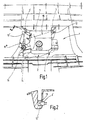
- Fig. 1 shows a section of an air conditioner housing 1, on which means a fastening device 2 described in more detail below Micromotor 10 is attached, for example, a fan of the air conditioner drives.
- the air conditioning case 1 is, at least in the area of Fastening device 2, made of polypropylene (PP).
- the fastening device 2 has two pocket-shaped receptacles 3, 3 ' on, which with appropriately designed areas of the housing 11th of the micromotor 10 cooperate. These areas of the housing 11 are arranged on arms 12, 12 'and each have a top and bottom one circular projection 13 whose dimensions substantially with the dimensions of the corresponding pocket-shaped receptacle 3, 3 ' matches. A section through one of the pocket-shaped receptacles 3 with the corresponding area of the housing 11 of the micro-motor 10 is in Fig. 2 shown.
- the housing 11 of the micromotor 10 also has a third arm 12 ", which is provided with a bore 14 through which in the final state Screw 15 protrudes, which in a provided in the fastening device 2 Thread is screwed.
- the first arm 12 For mounting the micromotor 10 on the air conditioning case 1 is the first arm 12 is positioned in the corresponding pocket-shaped receptacle 3, wherein the end of the first arm 12 is substantially positive fit interacts with the pocket-shaped receptacle 3, but a movement about a perpendicular to the first arm 12 arranged through the pocket-shaped Recording 3 extending axis is still possible. After that will the micromotor 10 is pivoted about this axis so that the second arm 12 'positively enters the corresponding pocket-shaped receptacle 3'. It is to support and guide the pivoting movement a Guiding device 4 is provided which part of the fastening device 2 is.
- the guide device 4 is formed by an appropriately trained Surface or rib formed, which is the height positioning of the micromotor 10 determines. Subsequently, the releasable fixation by means of Screw 15, which through the hole 14 in the third arm 12 "plugged in and screwed into the associated thread of the fastening device 2 becomes.
Landscapes
- Engineering & Computer Science (AREA)
- Power Engineering (AREA)
- Physics & Mathematics (AREA)
- Thermal Sciences (AREA)
- Mechanical Engineering (AREA)
- Connection Of Plates (AREA)
- Fixing For Electrophotography (AREA)
- Surgical Instruments (AREA)
- Developing Agents For Electrophotography (AREA)
- Motor Or Generator Frames (AREA)
- Air-Conditioning For Vehicles (AREA)
Abstract
Description
- Fig. 1
- eine Draufsicht auf einen Mikromotor und einer erfindungsgemäßen Befestigungsvorrichtung, wobei eine erste Position gestrichelt und eine zweite Position mit durchgezogener Linie dargestellt sind, und
- Fig. 2
- einen Schnitt durch einen Bereich von Fig. 1 entlang der Linie II-II.
- 1
- Klimaanlagen-Gehäuse
- 2
- Befestigungsvorrichtung
- 3,
- 3' taschenförmige Aufnahme
- 4
- Führungsvorrichtung
- 10
- Mikromotor
- 11
- Gehäuse Mikromotor
- 12, 12', 12"
- Arm
- 13
- Vorsprung
- 14
- Bohrung
- 15
- Schraube
Claims (11)
- Befestigungsvorrichtung für einen Mikromotor (10), insbesondere für eine Klimaanlage eines Kraftfahrzeugs, dadurch gekennzeichnet, dass die Befestigungsvorrichtung (2) zwei taschenförmige Aufnahmen (3, 3') aufweist, welche mit entsprechend ausgestalteten Bereichen des Mikromotors (10) zusammenwirken.
- Befestigungsvorrichtung nach Anspruch 1, dadurch gekennzeichnet, dass mindestens eine der taschenförmigen Aufnahmen (3) eine Schwenkbewegung ermöglicht.
- Befestigungsvorrichtung nach Anspruch 1 oder 2, dadurch gekennzeichnet, dass eine Führungsvorrichtung (4) vorgesehen ist.
- Befestigungsvorrichtung nach einem der vorhergehenden Ansprüche, dadurch gekennzeichnet, dass die taschenförmigen Aufnahmen (3, 3') mit am Ende abgerundeten Armen (12, 12') des Mikromotors (10) zusammenwirken.
- Befestigungsvorrichtung nach einem der vorhergehenden Ansprüche, dadurch gekennzeichnet, dass die zwei taschenförmigen Aufnahmen (3, 3') in Zusammenwirkung mit den entsprechenden Bereichen des Mikromotors (10) eine formschlüssige Verbindung mit einem Freiheitsgrad bilden.
- Befestigungsvorrichtung nach einem der vorhergehenden Ansprüche, dadurch gekennzeichnet, dass zur Fixierung des Mikromotors (10) ein Befestigungsmittel vorgesehen ist.
- Befestigungsvorrichtung nach einem der vorhergehenden Ansprüche, dadurch gekennzeichnet, dass das Befestigungsmittel durch eine Schraube (15) gebildet ist.
- Befestigungsvorrichtung nach Anspruch 7, dadurch gekennzeichnet, dass die Schraube (15) durch eine entsprechende Bohrung (14) im Gehäuse (11) des Mikromotors (10) ragt und in die mit einem Gewinde versehene Befestigungsvorrichtung (2) geschraubt ist.
- Befestigungsvorrichtung nach einem der vorhergehenden Ansprüche, dadurch gekennzeichnet, dass die Befestigungsvorrichtung (2) in ein Gehäuse (1) integriert ist.
- Befestigungsvorrichtung nach einem der vorhergehenden Ansprüche, dadurch gekennzeichnet, dass die Befestigungsvorrichtung (2) Teil eines Klimaanlagen-Gehäuses (1) ist.
- Befestigungsvorrichtung nach einem der vorhergehenden Ansprüche, dadurch gekennzeichnet, dass die Befestigungsvorrichtung (2) größtenteils aus Polypropylen besteht.
Priority Applications (4)
| Application Number | Priority Date | Filing Date | Title |
|---|---|---|---|
| EP03001568A EP1440827B1 (de) | 2003-01-23 | 2003-01-23 | Befestigungsvorrichtung für einen Mikromotor |
| ES03001568T ES2280633T3 (es) | 2003-01-23 | 2003-01-23 | Dispositivo de sujecion para un micromotor. |
| AT03001568T ATE352440T1 (de) | 2003-01-23 | 2003-01-23 | Befestigungsvorrichtung für einen mikromotor |
| DE50306366T DE50306366D1 (de) | 2003-01-23 | 2003-01-23 | Befestigungsvorrichtung für einen Mikromotor |
Applications Claiming Priority (1)
| Application Number | Priority Date | Filing Date | Title |
|---|---|---|---|
| EP03001568A EP1440827B1 (de) | 2003-01-23 | 2003-01-23 | Befestigungsvorrichtung für einen Mikromotor |
Publications (2)
| Publication Number | Publication Date |
|---|---|
| EP1440827A1 true EP1440827A1 (de) | 2004-07-28 |
| EP1440827B1 EP1440827B1 (de) | 2007-01-24 |
Family
ID=32524196
Family Applications (1)
| Application Number | Title | Priority Date | Filing Date |
|---|---|---|---|
| EP03001568A Expired - Lifetime EP1440827B1 (de) | 2003-01-23 | 2003-01-23 | Befestigungsvorrichtung für einen Mikromotor |
Country Status (4)
| Country | Link |
|---|---|
| EP (1) | EP1440827B1 (de) |
| AT (1) | ATE352440T1 (de) |
| DE (1) | DE50306366D1 (de) |
| ES (1) | ES2280633T3 (de) |
Cited By (1)
| Publication number | Priority date | Publication date | Assignee | Title |
|---|---|---|---|---|
| DE102004062425A1 (de) * | 2004-12-20 | 2006-06-29 | Behr Gmbh & Co. Kg | Gehäuse für ein Kraftfahrzeug-Belüftungssystem |
Citations (5)
| Publication number | Priority date | Publication date | Assignee | Title |
|---|---|---|---|---|
| DE2124304A1 (de) * | 1971-05-17 | 1972-11-30 | Volkswagenwerk Ag, 3180 Wolfsburg | Vorrichtung zum Befestigen von Zusatzaggregaten |
| DE8620239U1 (de) * | 1986-07-29 | 1986-09-25 | Bayerische Motoren Werke AG, 8000 München | Befestigungsanordnung für Elektro-Kleinmotoren, insbesondere für Schrittschalt-Getriebemotoren an Heiz- und/oder Klimaanlagen von Kraftfahrzeugen |
| DE4306588A1 (de) * | 1992-07-14 | 1994-01-20 | Bosch Gmbh Robert | Schwingungsdämpfende Halterung von Elektromotoren |
| DE19752258A1 (de) * | 1996-12-18 | 1998-06-25 | Valeo Climatisation | Vorrichtung zur Sicherung eines Getriebemotors an einem Heizungsgehäuse für ein Kraftfahrzeug |
| EP1216862A2 (de) * | 2000-12-20 | 2002-06-26 | Behr GmbH & Co. | Einrichtung zum Steuern von Luftströmen in einer Heiz- oder Klimaanlage eines Fahrzeuges |
-
2003
- 2003-01-23 AT AT03001568T patent/ATE352440T1/de not_active IP Right Cessation
- 2003-01-23 ES ES03001568T patent/ES2280633T3/es not_active Expired - Lifetime
- 2003-01-23 EP EP03001568A patent/EP1440827B1/de not_active Expired - Lifetime
- 2003-01-23 DE DE50306366T patent/DE50306366D1/de not_active Expired - Lifetime
Patent Citations (5)
| Publication number | Priority date | Publication date | Assignee | Title |
|---|---|---|---|---|
| DE2124304A1 (de) * | 1971-05-17 | 1972-11-30 | Volkswagenwerk Ag, 3180 Wolfsburg | Vorrichtung zum Befestigen von Zusatzaggregaten |
| DE8620239U1 (de) * | 1986-07-29 | 1986-09-25 | Bayerische Motoren Werke AG, 8000 München | Befestigungsanordnung für Elektro-Kleinmotoren, insbesondere für Schrittschalt-Getriebemotoren an Heiz- und/oder Klimaanlagen von Kraftfahrzeugen |
| DE4306588A1 (de) * | 1992-07-14 | 1994-01-20 | Bosch Gmbh Robert | Schwingungsdämpfende Halterung von Elektromotoren |
| DE19752258A1 (de) * | 1996-12-18 | 1998-06-25 | Valeo Climatisation | Vorrichtung zur Sicherung eines Getriebemotors an einem Heizungsgehäuse für ein Kraftfahrzeug |
| EP1216862A2 (de) * | 2000-12-20 | 2002-06-26 | Behr GmbH & Co. | Einrichtung zum Steuern von Luftströmen in einer Heiz- oder Klimaanlage eines Fahrzeuges |
Cited By (1)
| Publication number | Priority date | Publication date | Assignee | Title |
|---|---|---|---|---|
| DE102004062425A1 (de) * | 2004-12-20 | 2006-06-29 | Behr Gmbh & Co. Kg | Gehäuse für ein Kraftfahrzeug-Belüftungssystem |
Also Published As
| Publication number | Publication date |
|---|---|
| EP1440827B1 (de) | 2007-01-24 |
| ES2280633T3 (es) | 2007-09-16 |
| ATE352440T1 (de) | 2007-02-15 |
| DE50306366D1 (de) | 2007-03-15 |
Similar Documents
| Publication | Publication Date | Title |
|---|---|---|
| EP0694465A1 (de) | Kraftfahrzeugkarosserie mit integriertem Strukturquerträger | |
| DE112015000782T5 (de) | Clip zur Befestigung einer Platte an einem Träger, Verfahren zur Anwendung des Clips, und Motorfahrzeugausrüstung | |
| DE102013217939A1 (de) | Vorrichtung zur Halterung und Justierung eines Sensors | |
| DE102005062790A1 (de) | Scheibenwischer | |
| DE602005002868T2 (de) | Kraftfahrzeugrahmenanordnung | |
| DE102008024141A1 (de) | Spindel-Lageranordnung für ein Sitzlängsverstellgetriebe | |
| DE202004020237U1 (de) | Kunststoffbauteil | |
| DE102007014984B4 (de) | Befestigungselement mit dazugehörigem Stehbolzen | |
| EP1440827A1 (de) | Befestigungsvorrichtung für einen Mikromotor | |
| EP0943773A2 (de) | Positionierelement zur Ausrichtung von Karosserieteilen | |
| DE102004024088B4 (de) | Spreizclipverbindung zweier Bauteile | |
| EP1522441B1 (de) | Filteranordnung | |
| DE4142598C1 (en) | Glove pocket lid hinge - has fastener plate allocated to body-fixed tap with straps allowing plate to move in two dimensions relative to support | |
| DE10227237A1 (de) | Vorrichtung zum Toleranzausgleich für Montageverbindungen und Verbindungselement mit einer derartigen Vorrichtung | |
| DE102021129174B3 (de) | Halterung und Verfahren zur Befestigung einer Erfassungseinheit an einem Kraftfahrzeug mittels einer derartigen Halterung | |
| DE102005019078B4 (de) | Vorrichtung zur Montage eines Kraftfahrzeugsitzes | |
| DE4313739A1 (de) | Vorrichtung zum Befestigen eines zweiten Bauteils an einem ersten Bauteil | |
| DE29714671U1 (de) | Lochscheibe | |
| EP1676761B1 (de) | Scheibenwischvorrichtung | |
| DE2627382A1 (de) | Motoraufhaengung | |
| DE19942643C2 (de) | Verfahren zum Befestigen eines Seilfensterhebers an einer Fahrzeugtür sowie Fahrzeugtür eines Kraftfahrzeugs | |
| CH688445A5 (de) | Vorrichtung zur Befestigung einer Tafel an einer Unterlage. | |
| EP1492214A2 (de) | Aktuator | |
| DE102006001521B4 (de) | Vorrichtung zum exakten Positionieren einer Leuchte an der Karosserie eines Fahrzeuges | |
| DE102018204195A1 (de) | Spindelantrieb und Komfortantrieb mit einem Spindelantrieb |
Legal Events
| Date | Code | Title | Description |
|---|---|---|---|
| PUAI | Public reference made under article 153(3) epc to a published international application that has entered the european phase |
Free format text: ORIGINAL CODE: 0009012 |
|
| AK | Designated contracting states |
Kind code of ref document: A1 Designated state(s): AT BE BG CH CY CZ DE DK EE ES FI FR GB GR HU IE IT LI LU MC NL PT SE SI SK TR |
|
| AX | Request for extension of the european patent |
Extension state: AL LT LV MK RO |
|
| 17P | Request for examination filed |
Effective date: 20050128 |
|
| AKX | Designation fees paid |
Designated state(s): AT BE BG CH CY CZ DE DK EE ES FI FR GB GR HU IE IT LI LU MC NL PT SE SI SK TR |
|
| GRAP | Despatch of communication of intention to grant a patent |
Free format text: ORIGINAL CODE: EPIDOSNIGR1 |
|
| GRAS | Grant fee paid |
Free format text: ORIGINAL CODE: EPIDOSNIGR3 |
|
| GRAA | (expected) grant |
Free format text: ORIGINAL CODE: 0009210 |
|
| AK | Designated contracting states |
Kind code of ref document: B1 Designated state(s): AT BE BG CH CY CZ DE DK EE ES FI FR GB GR HU IE IT LI LU MC NL PT SE SI SK TR |
|
| PG25 | Lapsed in a contracting state [announced via postgrant information from national office to epo] |
Ref country code: SI Free format text: LAPSE BECAUSE OF FAILURE TO SUBMIT A TRANSLATION OF THE DESCRIPTION OR TO PAY THE FEE WITHIN THE PRESCRIBED TIME-LIMIT Effective date: 20070124 Ref country code: NL Free format text: LAPSE BECAUSE OF FAILURE TO SUBMIT A TRANSLATION OF THE DESCRIPTION OR TO PAY THE FEE WITHIN THE PRESCRIBED TIME-LIMIT Effective date: 20070124 Ref country code: IE Free format text: LAPSE BECAUSE OF FAILURE TO SUBMIT A TRANSLATION OF THE DESCRIPTION OR TO PAY THE FEE WITHIN THE PRESCRIBED TIME-LIMIT Effective date: 20070124 Ref country code: FI Free format text: LAPSE BECAUSE OF FAILURE TO SUBMIT A TRANSLATION OF THE DESCRIPTION OR TO PAY THE FEE WITHIN THE PRESCRIBED TIME-LIMIT Effective date: 20070124 Ref country code: DK Free format text: LAPSE BECAUSE OF FAILURE TO SUBMIT A TRANSLATION OF THE DESCRIPTION OR TO PAY THE FEE WITHIN THE PRESCRIBED TIME-LIMIT Effective date: 20070124 |
|
| REG | Reference to a national code |
Ref country code: GB Ref legal event code: FG4D Free format text: NOT ENGLISH |
|
| REG | Reference to a national code |
Ref country code: CH Ref legal event code: EP |
|
| REG | Reference to a national code |
Ref country code: IE Ref legal event code: FG4D Free format text: LANGUAGE OF EP DOCUMENT: GERMAN |
|
| REF | Corresponds to: |
Ref document number: 50306366 Country of ref document: DE Date of ref document: 20070315 Kind code of ref document: P |
|
| PG25 | Lapsed in a contracting state [announced via postgrant information from national office to epo] |
Ref country code: SE Free format text: LAPSE BECAUSE OF FAILURE TO SUBMIT A TRANSLATION OF THE DESCRIPTION OR TO PAY THE FEE WITHIN THE PRESCRIBED TIME-LIMIT Effective date: 20070424 |
|
| PG25 | Lapsed in a contracting state [announced via postgrant information from national office to epo] |
Ref country code: BG Free format text: LAPSE BECAUSE OF THE APPLICANT RENOUNCES Effective date: 20070425 |
|
| PG25 | Lapsed in a contracting state [announced via postgrant information from national office to epo] |
Ref country code: PT Free format text: LAPSE BECAUSE OF FAILURE TO SUBMIT A TRANSLATION OF THE DESCRIPTION OR TO PAY THE FEE WITHIN THE PRESCRIBED TIME-LIMIT Effective date: 20070625 |
|
| NLV1 | Nl: lapsed or annulled due to failure to fulfill the requirements of art. 29p and 29m of the patents act | ||
| ET | Fr: translation filed | ||
| GBV | Gb: ep patent (uk) treated as always having been void in accordance with gb section 77(7)/1977 [no translation filed] |
Effective date: 20070124 |
|
| REG | Reference to a national code |
Ref country code: IE Ref legal event code: FD4D |
|
| REG | Reference to a national code |
Ref country code: ES Ref legal event code: FG2A Ref document number: 2280633 Country of ref document: ES Kind code of ref document: T3 |
|
| PLBI | Opposition filed |
Free format text: ORIGINAL CODE: 0009260 |
|
| PG25 | Lapsed in a contracting state [announced via postgrant information from national office to epo] |
Ref country code: SK Free format text: LAPSE BECAUSE OF FAILURE TO SUBMIT A TRANSLATION OF THE DESCRIPTION OR TO PAY THE FEE WITHIN THE PRESCRIBED TIME-LIMIT Effective date: 20070124 Ref country code: GB Free format text: LAPSE BECAUSE OF FAILURE TO SUBMIT A TRANSLATION OF THE DESCRIPTION OR TO PAY THE FEE WITHIN THE PRESCRIBED TIME-LIMIT Effective date: 20070124 |
|
| 26 | Opposition filed |
Opponent name: VALEO SYSTEMES THERMIQUES S.A.S. Effective date: 20071024 |
|
| PLAX | Notice of opposition and request to file observation + time limit sent |
Free format text: ORIGINAL CODE: EPIDOSNOBS2 |
|
| PG25 | Lapsed in a contracting state [announced via postgrant information from national office to epo] |
Ref country code: CZ Free format text: LAPSE BECAUSE OF FAILURE TO SUBMIT A TRANSLATION OF THE DESCRIPTION OR TO PAY THE FEE WITHIN THE PRESCRIBED TIME-LIMIT Effective date: 20070124 |
|
| PLAF | Information modified related to communication of a notice of opposition and request to file observations + time limit |
Free format text: ORIGINAL CODE: EPIDOSCOBS2 |
|
| PG25 | Lapsed in a contracting state [announced via postgrant information from national office to epo] |
Ref country code: IT Free format text: LAPSE BECAUSE OF FAILURE TO SUBMIT A TRANSLATION OF THE DESCRIPTION OR TO PAY THE FEE WITHIN THE PRESCRIBED TIME-LIMIT Effective date: 20070124 Ref country code: GR Free format text: LAPSE BECAUSE OF FAILURE TO SUBMIT A TRANSLATION OF THE DESCRIPTION OR TO PAY THE FEE WITHIN THE PRESCRIBED TIME-LIMIT Effective date: 20070425 |
|
| PLBB | Reply of patent proprietor to notice(s) of opposition received |
Free format text: ORIGINAL CODE: EPIDOSNOBS3 |
|
| BERE | Be: lapsed |
Owner name: BEHR G.M.B.H. & CO. KG Effective date: 20080131 Owner name: FRAPE BEHR S.A. Effective date: 20080131 |
|
| PG25 | Lapsed in a contracting state [announced via postgrant information from national office to epo] |
Ref country code: MC Free format text: LAPSE BECAUSE OF NON-PAYMENT OF DUE FEES Effective date: 20080131 |
|
| REG | Reference to a national code |
Ref country code: CH Ref legal event code: PL |
|
| PG25 | Lapsed in a contracting state [announced via postgrant information from national office to epo] |
Ref country code: LI Free format text: LAPSE BECAUSE OF NON-PAYMENT OF DUE FEES Effective date: 20080131 Ref country code: CH Free format text: LAPSE BECAUSE OF NON-PAYMENT OF DUE FEES Effective date: 20080131 |
|
| PG25 | Lapsed in a contracting state [announced via postgrant information from national office to epo] |
Ref country code: EE Free format text: LAPSE BECAUSE OF FAILURE TO SUBMIT A TRANSLATION OF THE DESCRIPTION OR TO PAY THE FEE WITHIN THE PRESCRIBED TIME-LIMIT Effective date: 20070124 |
|
| PG25 | Lapsed in a contracting state [announced via postgrant information from national office to epo] |
Ref country code: BE Free format text: LAPSE BECAUSE OF NON-PAYMENT OF DUE FEES Effective date: 20080131 |
|
| PG25 | Lapsed in a contracting state [announced via postgrant information from national office to epo] |
Ref country code: AT Free format text: LAPSE BECAUSE OF NON-PAYMENT OF DUE FEES Effective date: 20080123 |
|
| PLCK | Communication despatched that opposition was rejected |
Free format text: ORIGINAL CODE: EPIDOSNREJ1 |
|
| PG25 | Lapsed in a contracting state [announced via postgrant information from national office to epo] |
Ref country code: CY Free format text: LAPSE BECAUSE OF FAILURE TO SUBMIT A TRANSLATION OF THE DESCRIPTION OR TO PAY THE FEE WITHIN THE PRESCRIBED TIME-LIMIT Effective date: 20070124 |
|
| PLBN | Opposition rejected |
Free format text: ORIGINAL CODE: 0009273 |
|
| STAA | Information on the status of an ep patent application or granted ep patent |
Free format text: STATUS: OPPOSITION REJECTED |
|
| 27O | Opposition rejected |
Effective date: 20090428 |
|
| PG25 | Lapsed in a contracting state [announced via postgrant information from national office to epo] |
Ref country code: LU Free format text: LAPSE BECAUSE OF NON-PAYMENT OF DUE FEES Effective date: 20080123 Ref country code: HU Free format text: LAPSE BECAUSE OF FAILURE TO SUBMIT A TRANSLATION OF THE DESCRIPTION OR TO PAY THE FEE WITHIN THE PRESCRIBED TIME-LIMIT Effective date: 20070725 |
|
| PG25 | Lapsed in a contracting state [announced via postgrant information from national office to epo] |
Ref country code: TR Free format text: LAPSE BECAUSE OF FAILURE TO SUBMIT A TRANSLATION OF THE DESCRIPTION OR TO PAY THE FEE WITHIN THE PRESCRIBED TIME-LIMIT Effective date: 20070124 |
|
| PGFP | Annual fee paid to national office [announced via postgrant information from national office to epo] |
Ref country code: ES Payment date: 20110119 Year of fee payment: 9 |
|
| REG | Reference to a national code |
Ref country code: ES Ref legal event code: FD2A Effective date: 20130708 |
|
| PG25 | Lapsed in a contracting state [announced via postgrant information from national office to epo] |
Ref country code: ES Free format text: LAPSE BECAUSE OF NON-PAYMENT OF DUE FEES Effective date: 20120124 |
|
| REG | Reference to a national code |
Ref country code: DE Ref legal event code: R082 Ref document number: 50306366 Country of ref document: DE Representative=s name: GRAUEL, ANDREAS, DIPL.-PHYS. DR. RER. NAT., DE |
|
| REG | Reference to a national code |
Ref country code: DE Ref legal event code: R082 Ref document number: 50306366 Country of ref document: DE Representative=s name: GRAUEL, ANDREAS, DIPL.-PHYS. DR. RER. NAT., DE Effective date: 20150519 Ref country code: DE Ref legal event code: R081 Ref document number: 50306366 Country of ref document: DE Owner name: MAHLE INTERNATIONAL GMBH, DE Free format text: FORMER OWNERS: BEHR GMBH & CO. KG, 70469 STUTTGART, DE; FRAPE BEHR S.A., BARCELONA, ES Effective date: 20150519 Ref country code: DE Ref legal event code: R081 Ref document number: 50306366 Country of ref document: DE Owner name: MAHLE INTERNATIONAL GMBH, DE Free format text: FORMER OWNER: BEHR GMBH & CO. KG, FRAPE BEHR S.A., , ES Effective date: 20150519 |
|
| REG | Reference to a national code |
Ref country code: FR Ref legal event code: PLFP Year of fee payment: 14 |
|
| REG | Reference to a national code |
Ref country code: FR Ref legal event code: PLFP Year of fee payment: 15 |
|
| REG | Reference to a national code |
Ref country code: FR Ref legal event code: PLFP Year of fee payment: 16 |
|
| PGFP | Annual fee paid to national office [announced via postgrant information from national office to epo] |
Ref country code: DE Payment date: 20200320 Year of fee payment: 18 |
|
| PGFP | Annual fee paid to national office [announced via postgrant information from national office to epo] |
Ref country code: FR Payment date: 20200128 Year of fee payment: 18 |
|
| REG | Reference to a national code |
Ref country code: DE Ref legal event code: R119 Ref document number: 50306366 Country of ref document: DE |
|
| PG25 | Lapsed in a contracting state [announced via postgrant information from national office to epo] |
Ref country code: FR Free format text: LAPSE BECAUSE OF NON-PAYMENT OF DUE FEES Effective date: 20210131 |
|
| PG25 | Lapsed in a contracting state [announced via postgrant information from national office to epo] |
Ref country code: DE Free format text: LAPSE BECAUSE OF NON-PAYMENT OF DUE FEES Effective date: 20210803 |