EP1440867A1 - Element de structure de conception pour véhicule automobile - Google Patents
Element de structure de conception pour véhicule automobile Download PDFInfo
- Publication number
- EP1440867A1 EP1440867A1 EP03001640A EP03001640A EP1440867A1 EP 1440867 A1 EP1440867 A1 EP 1440867A1 EP 03001640 A EP03001640 A EP 03001640A EP 03001640 A EP03001640 A EP 03001640A EP 1440867 A1 EP1440867 A1 EP 1440867A1
- Authority
- EP
- European Patent Office
- Prior art keywords
- structural design
- design component
- component
- bending
- initial
- Prior art date
- Legal status (The legal status is an assumption and is not a legal conclusion. Google has not performed a legal analysis and makes no representation as to the accuracy of the status listed.)
- Granted
Links
- 238000005452 bending Methods 0.000 claims abstract description 45
- 239000002184 metal Substances 0.000 claims description 9
- 230000001939 inductive effect Effects 0.000 claims description 7
- 238000010521 absorption reaction Methods 0.000 abstract description 11
- 238000006073 displacement reaction Methods 0.000 description 8
- 239000000463 material Substances 0.000 description 5
- 238000000034 method Methods 0.000 description 5
- 230000002787 reinforcement Effects 0.000 description 3
- 230000000694 effects Effects 0.000 description 2
- 239000007769 metal material Substances 0.000 description 2
- 238000003466 welding Methods 0.000 description 2
- 229910000831 Steel Inorganic materials 0.000 description 1
- 238000004026 adhesive bonding Methods 0.000 description 1
- 230000003111 delayed effect Effects 0.000 description 1
- 230000001419 dependent effect Effects 0.000 description 1
- 238000005457 optimization Methods 0.000 description 1
- 239000010959 steel Substances 0.000 description 1
- 238000006467 substitution reaction Methods 0.000 description 1
Images


Classifications
-
- B—PERFORMING OPERATIONS; TRANSPORTING
- B62—LAND VEHICLES FOR TRAVELLING OTHERWISE THAN ON RAILS
- B62D—MOTOR VEHICLES; TRAILERS
- B62D21/00—Understructures, i.e. chassis frame on which a vehicle body may be mounted
- B62D21/15—Understructures, i.e. chassis frame on which a vehicle body may be mounted having impact absorbing means, e.g. a frame designed to permanently or temporarily change shape or dimension upon impact with another body
- B62D21/152—Front or rear frames
Definitions
- the present patent application relates to a structural design component and in particular a structural design component for automotive vehicles having improved crash performance in accordance with the preamble of claim 1.
- a structural frame capable of absorbing impact energy which comprises a structural frame member of metallic material defining closed rectangular cross-section. Portion of each of the structural frame members is bent in the direction perpendicular to the longitudinal direction of the frame and energy absorption materials of metallic material with bowl-shaped projections are attached to those two opposing inner surfaces of the frame members which oppose in the direction of bending so that the bowl-shaped projections abut against each other.
- the shape of the cross-section of the structural frame may be maintained in its initial state and no abrupt decrease of bending moment takes place.
- One object of the invention is to provide an improved structural design component and in particular an improved structural design component for automotive vehicles providing for increased energy absorption during bending collapse of the member addressing the problems described in relation to the prior art arrangement.
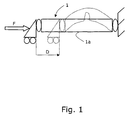
- Fig. 1 is a simplified side view of a structural design component in the shape of a elongated hollow sheet metal beam not incorporating the invention
- FIG. 2 is a schematic illustration of the typical force characteristic over displacement for the case illustrated in figure 1,
- Fig. 3 is a simplified side view of a structural design component in the shape of a elongated hollow sheet metal beam incorporating the invention
- FIG. 4 is a schematic illustration of the typical force characteristic over displacement for the case illustrated in figure 3,
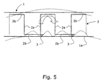
- Fig. 5 is a structural design component comprising a deformation control element in accordance with a preferred embodiment of the present invention.
- FIG. 1 A simplified side view of a structural design component in the shape of a elongated hollow sheet metal beam 1 not incorporating the invention is shown in figure 1.
- Full lines illustrates the beam 1 prior to being subject to a bending collapse mode and the dotted lines illustrates the beam 1 being subject to a bending collapse mode.
- Fig. 2 shows the typical force F characteristic over displacement D for the case illustrated in figure 1.
- the peak force F' is basically a factor of the geometry through the section bending stiffness, the length of the beam 1 and the modulus of the material.
- the local buckling coupled with the advent of bending moments in the beam 1 results in a loss of section in the beam 1 combined with an increase in stress levels due to the bending moments.
- the net effect is a very rapid loss of force carrying ability when the displacement D is increased.
- the force F eventually drops down to a residual level, this level being mainly a factor of the tensile stress of the material, the length and width of the beam 1 combined with the material thickness.
- Figure 3 illustrates a structural design component in the shape of a elongated hollow sheet metal beam 1 according to figure 1 incorporating a deformation control element (not shown) according to the invention.
- Full lines illustrates the beam 1 prior to being subject to a bending collapse mode and the dotted lines illustrates the beam 1 being subject to a bending collapse mode.
- the arrangement according to the invention results in the beam 1 buckling in multiple places in stead of one.
- the result is that there is an increased energy absorption during collapse.
- the deformation in accordance with figure 3 is achieved through providing inside the beam 1 a deformation control element having means for keeping the cross-section thereof up at a certain level, although local buckling has started. Hereby the force level is kept up after buckling has been initiated.
- the deformation control element further has means for causing the beam 1 to develop local buckling in multiple places, whereby the energy absorption of the design is optimized.
- the deformation control element By designing the deformation control element in such a way that it does not contribute to the beam 1 longitudinal stiffness in any significant amount, a preserved peak force level can be achieved. Hereby the need for special considerations and reinforcements of the attachment points between the beam and any surrounding structures can be eliminated.
- the deformation control element can also be designed to be somewhat deformed during the final stages of the bending collapse, which will also contribute somewhat to the energy absorption of the design.
- the force will increase rapidly and linearly as the displacement progresses essentially corresponding to figure 2.
- the peak force F' is basically a factor of the geometry through the section bending stiffness, the length of the beam 1 and the modulus of the material.
- the distributed buckling coupled with the presence of section maintaining means in the beam 1 results in a delayed loss of section in the beam 1. This results in a slower loss of force carrying ability when the displacement D is increased.
- the force F eventually drops down to a residual level, this level being higher than that of the beam 1 in accordance with figure 1.
- figure 5 is illustrated a possible design of a structural design component 1 comprising a deformation control element 2 in accordance with a preferred embodiment of the present invention.
- the deformation control element 2 is illustrated in a cut through side view of the hollow sheet metal beam 1 of figure 3.
- the beam 1 has a portion bendable when a collision load is applied in a longitudinal direction thereof.
- An initial closed cross-section of the beam 1 is essentially orthogonal to the longitudinal direction of the beam 1.
- the deformation control element 2 which provide means 2a arranged to, during the initial stages of bending, essentially maintain the initial cross-section of said bendable portion.
- These means 2a are here shown as part of the longitudinally extending deformation control element 2, and realized as multiple longitudinally spaced apart sheet members 2a arranged within said beam 1 essentially orthogonal to the longitudinal direction thereof and essentially filling out the initial closed cross-section thereof.
- These sheet members 2a are designed to keep the cross-section of the beam 1 up during the initial buckling.
- the sheet members 2a are spaced apart by essentially longitudinally extending spacing sections 2b of low bending stiffness, also part of the deformation control element 2.
- Each of said spacing sections 2b interconnect two of said sheet members 2a along an inner delimiting wall of said beam 1.
- the spacing sections 2b alternatingly are arranged along opposing inner delimiting walls of said beam 1, in order to minimize any contribution to the bending stiffness thereof.
- the deformation control element 2 further provide means 3 arranged to, during the initial stages of bending, induce local buckling at multiple distributed locations along a delimiting wall of said beam arranged to ,upon bending, being subject to negative pushing stresses. This local buckling at multiple distributed locations during bending collapse is illustrated with dotted lines in figure 5.
- the means 3 for inducing local buckling comprise longitudinally spaced apart interconnections 3 between said longitudinally extending deformation control element 2 and said delimiting wall of said beam 1, which wall is arranged to ,upon bending, provide an inner radius of curvature of said portion being subject to negative pushing stresses.
- the deformation control element 2 is connected to the beam 1 at locations where the bending stiffness of the deformation control element 2 is low, here illustrated as portions of the spacing sections 2b projecting slightly past the sheet members 2a, thus the stiffness contribution to the beam 1 is kept to a minimum.
- These interconnections 3 can also be arranged between at least two of the sheet members 2a and the delimiting wall of the beam 1. Alternatively these interconnections 3 can be arranged between at least two of said spacing sections 2b and said delimiting wall of the beam 1.
- the interconnections 3 further are arranged only at the side of the deformation control element 2 facing the side of the beam 1 intended to provide the inner radius of curvature during bending collapse, i.e. the side of the beam being subject to negative pushing stresses during bending.
- These interconnections 3 can be achieved in any suitable way, e.g. through welding, gluing or any other suitable method of interconnection known to the person skilled in the art. In the case of both the beam 1 and the deformation control element 2 being steel sheet metal structures, welding is usually the preferred method of interconnection.
- the deformation control element 2 must be continuous throughout the distance where the bending radius is designed to appear to have the desired effect of causing multiple distributed bending buckling modes during bending.
Landscapes
- Engineering & Computer Science (AREA)
- Chemical & Material Sciences (AREA)
- Combustion & Propulsion (AREA)
- Transportation (AREA)
- Mechanical Engineering (AREA)
- Body Structure For Vehicles (AREA)
Priority Applications (3)
| Application Number | Priority Date | Filing Date | Title |
|---|---|---|---|
| EP03001640A EP1440867B1 (fr) | 2003-01-24 | 2003-01-24 | Element de structure de conception pour véhicule automobile |
| DE60307413T DE60307413T2 (de) | 2003-01-24 | 2003-01-24 | Entwurf-Strukturbauteil für Kraftfahrzeug |
| US10/765,330 US20040222668A1 (en) | 2003-01-24 | 2004-01-26 | Structural design component for automotive vehicles |
Applications Claiming Priority (1)
| Application Number | Priority Date | Filing Date | Title |
|---|---|---|---|
| EP03001640A EP1440867B1 (fr) | 2003-01-24 | 2003-01-24 | Element de structure de conception pour véhicule automobile |
Publications (2)
| Publication Number | Publication Date |
|---|---|
| EP1440867A1 true EP1440867A1 (fr) | 2004-07-28 |
| EP1440867B1 EP1440867B1 (fr) | 2006-08-09 |
Family
ID=32524200
Family Applications (1)
| Application Number | Title | Priority Date | Filing Date |
|---|---|---|---|
| EP03001640A Expired - Lifetime EP1440867B1 (fr) | 2003-01-24 | 2003-01-24 | Element de structure de conception pour véhicule automobile |
Country Status (3)
| Country | Link |
|---|---|
| US (1) | US20040222668A1 (fr) |
| EP (1) | EP1440867B1 (fr) |
| DE (1) | DE60307413T2 (fr) |
Cited By (5)
| Publication number | Priority date | Publication date | Assignee | Title |
|---|---|---|---|---|
| US6883858B2 (en) | 2002-09-10 | 2005-04-26 | L & L Products, Inc. | Structural reinforcement member and method of use therefor |
| US6890021B2 (en) | 2001-09-24 | 2005-05-10 | L & L Products | Structural reinforcement system having modular segmented characteristics |
| US6953219B2 (en) | 2003-01-06 | 2005-10-11 | L&L Products, Inc. | Reinforcing members |
| US7025409B2 (en) | 2001-11-14 | 2006-04-11 | L & L Products, Inc. | Automotive rail/frame energy management system |
| US7180027B2 (en) | 2004-03-31 | 2007-02-20 | L & L Products, Inc. | Method of applying activatable material to a member |
Families Citing this family (1)
| Publication number | Priority date | Publication date | Assignee | Title |
|---|---|---|---|---|
| US7111899B2 (en) | 2003-04-23 | 2006-09-26 | L & L Products, Inc. | Structural reinforcement member and method of use therefor |
Citations (6)
| Publication number | Priority date | Publication date | Assignee | Title |
|---|---|---|---|---|
| US3827712A (en) * | 1971-12-08 | 1974-08-06 | Toyota Motor Co Ltd | Structural frame capable of absorbing impact energy |
| JPH0710033A (ja) * | 1993-06-25 | 1995-01-13 | Mitsubishi Motors Corp | 車両のサイドメンバ |
| JPH07149255A (ja) * | 1993-11-29 | 1995-06-13 | Toyota Motor Corp | 車体前部構造 |
| DE19731284A1 (de) * | 1997-07-21 | 1999-01-28 | Bayerische Motoren Werke Ag | Hohlträger |
| JPH11342862A (ja) * | 1998-01-08 | 1999-12-14 | Nissan Motor Co Ltd | 車両の強度部材の補強構造 |
| WO2001019666A1 (fr) * | 1999-09-15 | 2001-03-22 | Saab Ab | Procede et dispositif servant a limiter activement le comportement de deformation d'elements structuraux |
Family Cites Families (10)
| Publication number | Priority date | Publication date | Assignee | Title |
|---|---|---|---|---|
| US4413840A (en) * | 1981-09-14 | 1983-11-08 | Ford Motor Company | Mechanism to control axial collapse of an open cross-section beam |
| DE4028164A1 (de) * | 1990-07-17 | 1992-01-23 | Schneider Gesenkschmiede | Pralldaempfer |
| JP2563632Y2 (ja) * | 1990-11-29 | 1998-02-25 | マツダ株式会社 | 自動車の前部車体構造 |
| FR2710893B1 (fr) * | 1993-10-05 | 1995-11-17 | Smh Management Services Ag | Châssis pour véhicule, notamment pour véhicule automobile. |
| US5732801A (en) * | 1996-08-05 | 1998-03-31 | Gertz; David C. | Energy absorbing bumper support structure |
| JP3478317B2 (ja) * | 1996-08-21 | 2003-12-15 | 三菱自動車工業株式会社 | ボデーの構造 |
| DE10053840A1 (de) * | 2000-10-30 | 2002-05-08 | Bayer Ag | Stoßfängersystem für Fahrzeuge |
| EP1325859B1 (fr) * | 2001-11-13 | 2017-03-22 | Nissan Motor Co., Ltd. | Structure de chassis avant d'un véhicule optimisant l'absorption d'énergie en cas de collision |
| US6793274B2 (en) * | 2001-11-14 | 2004-09-21 | L&L Products, Inc. | Automotive rail/frame energy management system |
| DE60219275T2 (de) * | 2002-01-16 | 2008-01-03 | Nissan Motor Co., Ltd., Yokohama | Verstärkungskonstruktion für Karosserierahmen von Kraftfahrzeugen |
-
2003
- 2003-01-24 EP EP03001640A patent/EP1440867B1/fr not_active Expired - Lifetime
- 2003-01-24 DE DE60307413T patent/DE60307413T2/de not_active Expired - Lifetime
-
2004
- 2004-01-26 US US10/765,330 patent/US20040222668A1/en not_active Abandoned
Patent Citations (6)
| Publication number | Priority date | Publication date | Assignee | Title |
|---|---|---|---|---|
| US3827712A (en) * | 1971-12-08 | 1974-08-06 | Toyota Motor Co Ltd | Structural frame capable of absorbing impact energy |
| JPH0710033A (ja) * | 1993-06-25 | 1995-01-13 | Mitsubishi Motors Corp | 車両のサイドメンバ |
| JPH07149255A (ja) * | 1993-11-29 | 1995-06-13 | Toyota Motor Corp | 車体前部構造 |
| DE19731284A1 (de) * | 1997-07-21 | 1999-01-28 | Bayerische Motoren Werke Ag | Hohlträger |
| JPH11342862A (ja) * | 1998-01-08 | 1999-12-14 | Nissan Motor Co Ltd | 車両の強度部材の補強構造 |
| WO2001019666A1 (fr) * | 1999-09-15 | 2001-03-22 | Saab Ab | Procede et dispositif servant a limiter activement le comportement de deformation d'elements structuraux |
Non-Patent Citations (3)
| Title |
|---|
| PATENT ABSTRACTS OF JAPAN vol. 1995, no. 04 31 May 1995 (1995-05-31) * |
| PATENT ABSTRACTS OF JAPAN vol. 1995, no. 09 31 October 1995 (1995-10-31) * |
| PATENT ABSTRACTS OF JAPAN vol. 2000, no. 03 30 March 2000 (2000-03-30) * |
Cited By (8)
| Publication number | Priority date | Publication date | Assignee | Title |
|---|---|---|---|---|
| US6890021B2 (en) | 2001-09-24 | 2005-05-10 | L & L Products | Structural reinforcement system having modular segmented characteristics |
| US7025409B2 (en) | 2001-11-14 | 2006-04-11 | L & L Products, Inc. | Automotive rail/frame energy management system |
| US7114763B2 (en) | 2001-11-14 | 2006-10-03 | L & L Products, Inc. | Automotive rail/frame energy management system |
| US6883858B2 (en) | 2002-09-10 | 2005-04-26 | L & L Products, Inc. | Structural reinforcement member and method of use therefor |
| US6932421B2 (en) | 2002-09-10 | 2005-08-23 | L & L Products, Inc. | Structural reinforcement member and method of use therefor |
| US6953219B2 (en) | 2003-01-06 | 2005-10-11 | L&L Products, Inc. | Reinforcing members |
| US7478478B2 (en) | 2003-01-06 | 2009-01-20 | Zephyros, Inc. | Method of providing reinforcing members |
| US7180027B2 (en) | 2004-03-31 | 2007-02-20 | L & L Products, Inc. | Method of applying activatable material to a member |
Also Published As
| Publication number | Publication date |
|---|---|
| DE60307413T2 (de) | 2007-03-29 |
| DE60307413D1 (de) | 2006-09-21 |
| EP1440867B1 (fr) | 2006-08-09 |
| US20040222668A1 (en) | 2004-11-11 |
Similar Documents
| Publication | Publication Date | Title |
|---|---|---|
| US7461874B2 (en) | Selectively annealed bumper beam | |
| EP1876085B1 (fr) | Capot de moteur d'un véhicule automobile | |
| US7063376B2 (en) | Structural member for a vehicle frame assembly | |
| US6793246B2 (en) | Knee support for occupants | |
| CN109963751B (zh) | 在保险杠梁的若干壁上具有肋的保险杠梁 | |
| KR101166641B1 (ko) | 범퍼 빔 | |
| JP2005532207A (ja) | ビークル用の中空鋼長尺断面材製支持構造 | |
| JP2005532207A5 (fr) | ||
| EP4335729A1 (fr) | Carrosserie de véhicule | |
| JPH04310477A (ja) | 車両のサイドメンバ | |
| CN108495777A (zh) | 车辆前部构造 | |
| US20160244013A1 (en) | Vehicle bumper reinforcement structure | |
| JP2002154327A (ja) | 自動車ドアのインパクトビーム | |
| JP2025531713A (ja) | 車両用フロントレール | |
| CN114375266A (zh) | 具有溃压箱支架的车辆保险杠扩展件 | |
| EP1440867A1 (fr) | Element de structure de conception pour véhicule automobile | |
| JP4035292B2 (ja) | オフセット衝突性に優れたバンパー補強材 | |
| JP5235007B2 (ja) | クラッシュボックス | |
| JP4830017B2 (ja) | 乗用車用バンパー構造体 | |
| JP4895739B2 (ja) | バンパー構造体 | |
| JP2001225763A (ja) | 車体用エネルギー吸収部材 | |
| JP2003291755A (ja) | 衝突エネルギー吸収要素 | |
| JP4039032B2 (ja) | 衝突エネルギー吸収部材 | |
| EP3722185B1 (fr) | Élément poussoir latéral | |
| JP2006335241A (ja) | バンパステイおよびバンパ装置 |
Legal Events
| Date | Code | Title | Description |
|---|---|---|---|
| PUAI | Public reference made under article 153(3) epc to a published international application that has entered the european phase |
Free format text: ORIGINAL CODE: 0009012 |
|
| AK | Designated contracting states |
Kind code of ref document: A1 Designated state(s): AT BE BG CH CY CZ DE DK EE ES FI FR GB GR HU IE IT LI LU MC NL PT SE SI SK TR |
|
| AX | Request for extension of the european patent |
Extension state: AL LT LV MK RO |
|
| 17P | Request for examination filed |
Effective date: 20040920 |
|
| 17Q | First examination report despatched |
Effective date: 20050224 |
|
| AKX | Designation fees paid |
Designated state(s): DE GB SE |
|
| GRAP | Despatch of communication of intention to grant a patent |
Free format text: ORIGINAL CODE: EPIDOSNIGR1 |
|
| GRAS | Grant fee paid |
Free format text: ORIGINAL CODE: EPIDOSNIGR3 |
|
| GRAA | (expected) grant |
Free format text: ORIGINAL CODE: 0009210 |
|
| AK | Designated contracting states |
Kind code of ref document: B1 Designated state(s): DE GB SE |
|
| REG | Reference to a national code |
Ref country code: GB Ref legal event code: FG4D |
|
| RAP2 | Party data changed (patent owner data changed or rights of a patent transferred) |
Owner name: FORD GLOBAL TECHNOLOGIES, LLC. |
|
| REF | Corresponds to: |
Ref document number: 60307413 Country of ref document: DE Date of ref document: 20060921 Kind code of ref document: P |
|
| REG | Reference to a national code |
Ref country code: SE Ref legal event code: TRGR |
|
| PLBE | No opposition filed within time limit |
Free format text: ORIGINAL CODE: 0009261 |
|
| STAA | Information on the status of an ep patent application or granted ep patent |
Free format text: STATUS: NO OPPOSITION FILED WITHIN TIME LIMIT |
|
| 26N | No opposition filed |
Effective date: 20070510 |
|
| REG | Reference to a national code |
Ref country code: DE Ref legal event code: R082 Ref document number: 60307413 Country of ref document: DE Representative=s name: LOUIS, POEHLAU, LOHRENTZ, DE |
|
| REG | Reference to a national code |
Ref country code: DE Ref legal event code: R082 Ref document number: 60307413 Country of ref document: DE Representative=s name: LOUIS, POEHLAU, LOHRENTZ, DE Effective date: 20120207 Ref country code: DE Ref legal event code: R081 Ref document number: 60307413 Country of ref document: DE Owner name: VOLVO CAR CORPORATION, SE Free format text: FORMER OWNER: FORD GLOBAL TECHNOLOGIES, LLC, DEARBORN, MICH., US Effective date: 20120207 Ref country code: DE Ref legal event code: R081 Ref document number: 60307413 Country of ref document: DE Owner name: VOLVO CAR CORPORATION, SE Free format text: FORMER OWNER: FORD GLOBAL TECHNOLOGIES, LLC, DEARBORN, US Effective date: 20120207 |
|
| REG | Reference to a national code |
Ref country code: GB Ref legal event code: 732E Free format text: REGISTERED BETWEEN 20120510 AND 20120516 |
|
| REG | Reference to a national code |
Ref country code: GB Ref legal event code: 732E Free format text: REGISTERED BETWEEN 20120517 AND 20120523 |
|
| PGFP | Annual fee paid to national office [announced via postgrant information from national office to epo] |
Ref country code: SE Payment date: 20150123 Year of fee payment: 13 Ref country code: GB Payment date: 20150120 Year of fee payment: 13 |
|
| GBPC | Gb: european patent ceased through non-payment of renewal fee |
Effective date: 20160124 |
|
| PG25 | Lapsed in a contracting state [announced via postgrant information from national office to epo] |
Ref country code: GB Free format text: LAPSE BECAUSE OF NON-PAYMENT OF DUE FEES Effective date: 20160124 |
|
| PG25 | Lapsed in a contracting state [announced via postgrant information from national office to epo] |
Ref country code: SE Free format text: LAPSE BECAUSE OF NON-PAYMENT OF DUE FEES Effective date: 20160125 |
|
| PGFP | Annual fee paid to national office [announced via postgrant information from national office to epo] |
Ref country code: DE Payment date: 20170116 Year of fee payment: 15 |
|
| REG | Reference to a national code |
Ref country code: DE Ref legal event code: R119 Ref document number: 60307413 Country of ref document: DE |
|
| PG25 | Lapsed in a contracting state [announced via postgrant information from national office to epo] |
Ref country code: DE Free format text: LAPSE BECAUSE OF NON-PAYMENT OF DUE FEES Effective date: 20180801 |