EP1440898B1 - Fermeture a glissiere en plastique et corps de sac a fermeture en plastique - Google Patents
Fermeture a glissiere en plastique et corps de sac a fermeture en plastique Download PDFInfo
- Publication number
- EP1440898B1 EP1440898B1 EP01961349A EP01961349A EP1440898B1 EP 1440898 B1 EP1440898 B1 EP 1440898B1 EP 01961349 A EP01961349 A EP 01961349A EP 01961349 A EP01961349 A EP 01961349A EP 1440898 B1 EP1440898 B1 EP 1440898B1
- Authority
- EP
- European Patent Office
- Prior art keywords
- zipper
- slider
- opening
- plastic
- hermetically sealing
- Prior art date
- Legal status (The legal status is an assumption and is not a legal conclusion. Google has not performed a legal analysis and makes no representation as to the accuracy of the status listed.)
- Expired - Lifetime
Links
- 229920003023 plastic Polymers 0.000 title claims description 85
- 239000004033 plastic Substances 0.000 title claims description 85
- 238000007789 sealing Methods 0.000 claims description 65
- 239000002985 plastic film Substances 0.000 claims description 6
- 229920006255 plastic film Polymers 0.000 claims description 6
- 238000000034 method Methods 0.000 description 5
- 230000000052 comparative effect Effects 0.000 description 4
- 238000004806 packaging method and process Methods 0.000 description 4
- 229920000092 linear low density polyethylene Polymers 0.000 description 3
- 239000004707 linear low-density polyethylene Substances 0.000 description 3
- 229920001684 low density polyethylene Polymers 0.000 description 3
- 239000004702 low-density polyethylene Substances 0.000 description 3
- 238000005259 measurement Methods 0.000 description 3
- 238000012360 testing method Methods 0.000 description 3
- 239000000470 constituent Substances 0.000 description 2
- 239000003814 drug Substances 0.000 description 2
- 235000013305 food Nutrition 0.000 description 2
- 239000007788 liquid Substances 0.000 description 2
- 239000005022 packaging material Substances 0.000 description 2
- 238000009877 rendering Methods 0.000 description 2
- 230000002159 abnormal effect Effects 0.000 description 1
- 238000010276 construction Methods 0.000 description 1
- 238000011109 contamination Methods 0.000 description 1
- 230000001419 dependent effect Effects 0.000 description 1
- 238000011161 development Methods 0.000 description 1
- 230000000694 effects Effects 0.000 description 1
- 238000011835 investigation Methods 0.000 description 1
- 239000000463 material Substances 0.000 description 1
- 230000002085 persistent effect Effects 0.000 description 1
- 230000002265 prevention Effects 0.000 description 1
- 238000011160 research Methods 0.000 description 1
Images


Classifications
-
- B—PERFORMING OPERATIONS; TRANSPORTING
- B65—CONVEYING; PACKING; STORING; HANDLING THIN OR FILAMENTARY MATERIAL
- B65D—CONTAINERS FOR STORAGE OR TRANSPORT OF ARTICLES OR MATERIALS, e.g. BAGS, BARRELS, BOTTLES, BOXES, CANS, CARTONS, CRATES, DRUMS, JARS, TANKS, HOPPERS, FORWARDING CONTAINERS; ACCESSORIES, CLOSURES, OR FITTINGS THEREFOR; PACKAGING ELEMENTS; PACKAGES
- B65D33/00—Details of, or accessories for, sacks or bags
- B65D33/16—End- or aperture-closing arrangements or devices
- B65D33/25—Riveting; Dovetailing; Screwing; using press buttons or slide fasteners
- B65D33/2508—Riveting; Dovetailing; Screwing; using press buttons or slide fasteners using slide fasteners with interlocking members having a substantially uniform section throughout the length of the fastener; Sliders therefor
- B65D33/2584—Riveting; Dovetailing; Screwing; using press buttons or slide fasteners using slide fasteners with interlocking members having a substantially uniform section throughout the length of the fastener; Sliders therefor characterized by the slider
- B65D33/2586—Riveting; Dovetailing; Screwing; using press buttons or slide fasteners using slide fasteners with interlocking members having a substantially uniform section throughout the length of the fastener; Sliders therefor characterized by the slider being provided with a separating plow
- B65D33/25865—Riveting; Dovetailing; Screwing; using press buttons or slide fasteners using slide fasteners with interlocking members having a substantially uniform section throughout the length of the fastener; Sliders therefor characterized by the slider being provided with a separating plow reaching between the interlocking fastener profiles
-
- B—PERFORMING OPERATIONS; TRANSPORTING
- B65—CONVEYING; PACKING; STORING; HANDLING THIN OR FILAMENTARY MATERIAL
- B65D—CONTAINERS FOR STORAGE OR TRANSPORT OF ARTICLES OR MATERIALS, e.g. BAGS, BARRELS, BOTTLES, BOXES, CANS, CARTONS, CRATES, DRUMS, JARS, TANKS, HOPPERS, FORWARDING CONTAINERS; ACCESSORIES, CLOSURES, OR FITTINGS THEREFOR; PACKAGING ELEMENTS; PACKAGES
- B65D33/00—Details of, or accessories for, sacks or bags
- B65D33/16—End- or aperture-closing arrangements or devices
- B65D33/25—Riveting; Dovetailing; Screwing; using press buttons or slide fasteners
- B65D33/2508—Riveting; Dovetailing; Screwing; using press buttons or slide fasteners using slide fasteners with interlocking members having a substantially uniform section throughout the length of the fastener; Sliders therefor
-
- A—HUMAN NECESSITIES
- A44—HABERDASHERY; JEWELLERY
- A44B—BUTTONS, PINS, BUCKLES, SLIDE FASTENERS, OR THE LIKE
- A44B19/00—Slide fasteners
- A44B19/10—Slide fasteners with a one-piece interlocking member on each stringer tape
- A44B19/16—Interlocking member having uniform section throughout the length of the stringer
-
- A—HUMAN NECESSITIES
- A44—HABERDASHERY; JEWELLERY
- A44B—BUTTONS, PINS, BUCKLES, SLIDE FASTENERS, OR THE LIKE
- A44B19/00—Slide fasteners
- A44B19/24—Details
- A44B19/26—Sliders
- A44B19/267—Sliders for slide fasteners with edges of stringers having uniform section throughout the length thereof
-
- Y—GENERAL TAGGING OF NEW TECHNOLOGICAL DEVELOPMENTS; GENERAL TAGGING OF CROSS-SECTIONAL TECHNOLOGIES SPANNING OVER SEVERAL SECTIONS OF THE IPC; TECHNICAL SUBJECTS COVERED BY FORMER USPC CROSS-REFERENCE ART COLLECTIONS [XRACs] AND DIGESTS
- Y10—TECHNICAL SUBJECTS COVERED BY FORMER USPC
- Y10T—TECHNICAL SUBJECTS COVERED BY FORMER US CLASSIFICATION
- Y10T24/00—Buckles, buttons, clasps, etc.
- Y10T24/15—Bag fasteners
-
- Y—GENERAL TAGGING OF NEW TECHNOLOGICAL DEVELOPMENTS; GENERAL TAGGING OF CROSS-SECTIONAL TECHNOLOGIES SPANNING OVER SEVERAL SECTIONS OF THE IPC; TECHNICAL SUBJECTS COVERED BY FORMER USPC CROSS-REFERENCE ART COLLECTIONS [XRACs] AND DIGESTS
- Y10—TECHNICAL SUBJECTS COVERED BY FORMER USPC
- Y10T—TECHNICAL SUBJECTS COVERED BY FORMER US CLASSIFICATION
- Y10T24/00—Buckles, buttons, clasps, etc.
- Y10T24/25—Zipper or required component thereof
- Y10T24/2532—Zipper or required component thereof having interlocking surface with continuous cross section
- Y10T24/2534—Opposed interlocking surface having dissimilar cross section
-
- Y—GENERAL TAGGING OF NEW TECHNOLOGICAL DEVELOPMENTS; GENERAL TAGGING OF CROSS-SECTIONAL TECHNOLOGIES SPANNING OVER SEVERAL SECTIONS OF THE IPC; TECHNICAL SUBJECTS COVERED BY FORMER USPC CROSS-REFERENCE ART COLLECTIONS [XRACs] AND DIGESTS
- Y10—TECHNICAL SUBJECTS COVERED BY FORMER USPC
- Y10T—TECHNICAL SUBJECTS COVERED BY FORMER US CLASSIFICATION
- Y10T24/00—Buckles, buttons, clasps, etc.
- Y10T24/26—Slit closing means including guides on opposite edges of slit and slidable bridging component
- Y10T24/262—Slit closing means including guides on opposite edges of slit and slidable bridging component with hand-actuated lever for shifting bridging component
Definitions
- the present invention relates to a plastic zipper equipped with a slider which zipper is employed as packaging materials for foods, pharmaceuticals, electronic part items and the like, and which is capable of keeping hermetical sealability even after repeated opening and closing operations, and which enables easy opening and resealing. It also pertains to a bag body equipped with the above-mentioned plastic zipper.
- bag bodies each equipped on the opening portion with a plastic zipper composed of a pair of male and female hooks on a surface of a plastic film.
- plastic zippers each equipped with a slider which is used for opening and closing the zippers because of easiness in opening and closing operations.
- This slider is composed of an outside guide and an inside guide.
- the slider which is usually employed is of such a structure that the inside guide is inserted between the male and the female hooks and causes the male/female hooks to disengage, while the outside guide causes the male/female hooks to engage ⁇ refer to JP-A-214920 / 1996 (Heisei 8) ⁇ .
- the inside guide is inserted between the hooks of a zipper, even if the zipper is completely bound tight, the content in a bag leaks through a gap between the hooks and the inside guide which is inserted between the hooks.
- the above-mentioned zipper is not usable for applications requiring hermetical sealing except for applications only not requiring hermetical sealing such as general cargoes.
- a zipper having such a structure that hermetical sealing can be maintained in a state of a bag being closed with a slider by the use of a specially shaped plastic zipper and a slider adapted thereto (for instance, US-A-5,067,208 and US-A-5,664,299 ).
- hermetical sealability is maintained by taking advantage of the elasticity of the plastic material which constitutes the zipper for the purpose of facilitating the disengagement even with a weak force, and therefore when the elasticity thereof varies with a variation in temperature or the like, there is caused a danger of incapability of maintaining the hermetical sealability after opening and closing operations, whereby the amount of leakage is increased.
- the above-proposed zippers are not usable for packaging such content as liquid and the like in which occurrence of leakage is forbidden.
- the present inventor previously proposed a hermetically sealable plastic zipper characterized by forming male hooks and female hooks of the zipper on the surface of a plastic, forming a continuous tightening wall parallel to the male hooks on the inside thereof, and further forming a continuous pressing rib parallel to the female hooks on the inside thereof, so that the zipper is imparted with excellent properties in persistent hermetical-sealability and also impact resistance by tight contact between the continuous tightening wall and the continuous pressing rib as well as selftightening effect thereof ( JP-C-2,938,784 ).
- the hermetically sealable plastic zipper is excellent in hermetical sealability and impact resistance and almost free from performance variation due to temperature variation, and accordingly is well suited for packaging liquid and the like.
- the present inventor previously proposed a slider shown in JP-A-130594 / 2001 (Heisei 13) which was adapted to the aforesaid hermetically sealable plastic zipper and which does not impair the hermetical sealability thereof, and a plastic zipper equipped with the above-mentioned slider.
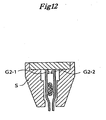
- the constitution thereof is such that as illustrated on FIG.
- protrusions G 2 - 1, G 2 - 2 each serving as guide for the slider are installed on the opening portion side flange portion (extension portion) of opening side hook so that the protrusions are parallel to the slider, and also an inside guide S - 1 is installed on the plate portion C of the slider S so that the inside guide is positioned between the protrusions and the hooks on the side of the opening portion of the zipper, so as to enable the hermetically sealable plastic zipper to be opened and closed by sliding the slider S as illustrated on FIG. 12 and FIG. 13 .
- the plastic zipper equipped with said slider and a bag body equipped with said zipper suffer from the disadvantage in that unjust unsealing is not preventable, since the plastic zipper in closed state can readily be opened by pulling the aforesaid protrusions G 2 - 1, G 2 - 2 with the slider S from the outside of the zipper.
- the aforesaid slider of such constitution that enables unjust unsealing even after being closed involves a danger of causing contamination with foreign matters or abnormal quality due to unjust unsealing.
- the present inventor previously proposed a plastic zipper which was equipped with a slider and which was capable of performing completely sealed packaging with a zipper alone and of detecting that unsealing had been made after the sealed packaging, and a bag body equipped with the zipper ⁇ refer to
- the plastic zipper which is equipped with a slider and a means for detecting unjust unsealing and a bag body equipped with the zipper each comprise a pair of male hook and female hook formed on a plastic surface, have a continuous tightening wall 1 - 2 and a continuous pressing rib 1 - 4 that are parallel to the male hooks 1 - 1 on the inside thereof, and are equipped with means for bonding the surfaces of the continuous tightening wall 1 - 2 and the continuous pressing rib 1 - 4 with easily peelable plastic layers A - 1, B - 1 in a state of the zipper being engaged and means for bonding the protrusions G 2 - 1, G 2 - 2 each serving as a guide for the slider that are formed parallel to a pair of male and female hooks 5 - 1, 5 - 2 on the plastic surfaces with easily peelable plastic layers A - 8, B - 8 in a state of the zipper being engaged.
- the above-mentioned means are capable of easily opening and closing the zipper by means of the slider as disclosed in the aforesaid
- JP-C-3,026,839 describes a method for opening and closing the zipper fitted with a rib on the end portion of a flange attached to the opening side of the zipper by use of a slider having a vertical lower side wall portion and a member of inverse U shape.
- the method although being easy to obtain the opening force, is required to enlarge the member of inverse U shape inside the slider, when applied to the hermetically sealable zipper which is disclosed in the a foresaid JP-C-2,938,784 relating to the proposal of the present inventor and which is excellent in hermetical sealability and the like. Consequently the method is not applicable to a small bag.
- the present inventor proposed a plastic zipper equipped with a slider and imparted with a means for preventing unjust unsealing, characterized in that the plastic zipper which is equipped with a slider and a pair of male and female hooks for sealing formed on plastic surfaces is fitted with a pair of male and female hooks for guiding the slider parallel to the hooks for sealing on the opening side, and the inside guide for the slider is positioned between the hooks for sealing and the hooks for guiding the slider ⁇ JP-A-375501 / 2000 (Heisei 12) ⁇ .
- the constitution of the aforesaid plastic zipper is such that the hooks for guiding the slider is firstly opened, and the hooks for sealing are opened by catching the inside guide for the slider on the hooks for guiding the slider thus opened. It is possible to simultaneously use these inventions, that is, to install a pair of male and female hooks for guiding the slider parallel to the hooks for sealing on the opening side of the plastic zipper in which the surfaces of the above-mentioned continuous tightening wall and continuous pressing rib are bonded with easily peelable plastic layers. Nevertheless, as is the case with the slider mentioned before, the slider just mentioned involves the problem of being unapplicable to a small bag. Under such circumstances, the development of a plastic zipper equipped with a slider capable of markedly increasing an opening force in spite of its being miniaturized has eagerly been desired.
- the object of the present invention is to provide a hermetically sealable plastic zipper equipped with a slider suitable also for small bags without impairing the characteristics of the zipper even if the zipper requires an extremely high opening strength.
- the present inventor has developped a plastic zipper equipped with a slider, which zipper is capable of markedly increasing the opening force required in spite of its being miniaturized, and a bag body equipped with said zipper, in order to apply a plastic zipper equipped with a slider to small bags without impairing the characteristics of the zipper even if the zipper requires an extremely high opening strength as is the case with a hermetically sealable zipper in which the above-mentioned continuous tightening wall and continuous pressing rib are bonded with easily peelable plastic layers.
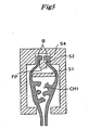
- FIG. 1 is a schematic perspective view showing a partially cutaway bag body equipped with a plastic zipper fitted with a slider.
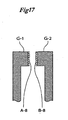
- FIG. 2 through FIG. 4 are each a cross sectional view taken along line A - A' of a slider opening end in FIG. 1 , a cross sectional view taken along line B - B' of an opening plate in FIG. 1 , and a cross sectional view taken along line C - C' of the slider closing end in FIG. 1 , respectively.
- FIG. 5 and FIG. 6 are each a cross sectional view and a fragmentary sectional view, respectively, both corresponding to FIG. 3 and illustrating a rib of a different shape instead of a second zipper.
- F is a plastic film
- F 2 / M 2 are each a female hook in a second zipper and a male hook in the same, respectively.
- F 1 - 1 and F 1 - 2 are each a female hook for a hermetically sealable plastic zipper
- M 1 - 1 and M 1 - 2 are each a male hook for the hermetically sealable zipper
- R 1 and R 2 are each a continuous pressing wall and a continuous pressing rib, respectively
- S is a slider
- S 1 is an opening plate
- S 2 is a cover
- S 3 is an opening stanchion
- S 4 is a connecting groove
- S 5 is a protrusion for preventing falling off
- S 6 is a closing wall for a hermetically sealing plastic zipper
- S 7 is a closing wall for a second zipper
- B is a rib
- E 1 is an opening end of a zipper
- E 2 is a closing end of a zipper.
- a hermetically sealing zipper CH 1 is formed on the surface of the plastic film F, which comprises the pairs of male and female hooks F 1 - 1, F 1 - 2, M 1 - 1, 1 - 2; the continuous pressing wall R 1; and the continuous pressing rib R 2.
- the hermetically sealing zipper is opened and closed by means of the slider S, a flange (extension portion) FL is installed on each opening portion side of male and female hooks for the hermetically sealing zipper CH 1, and a second zipper CH 2 composed of a pair of male and female hooks is installed on each end portion of the flange FL.
- the width of the connecting groove S 4 used for keeping a closed state of the hermetically sealing zipper CH 1 after its opening is made larger than the width of the opening stanchion S 3 immediately in front thereof, whereby the function of the groove for opening prevention is substantially eliminated or the connecting groove itself is removed. Thereafter as illustrated on FIG. 2 , the opening stanchion S 3 is used to open the second zipper CH 2, whereby the bag equipped with the zipper is opened.
- a rib B illustrated on FIG. 5 or FIG. 6 may be used in place of the second zipper CH 2.
- the shape of the rib B is not limited to rectangle, but may be of a different shape such as triangle or semicircle.
- the hermetically sealing zipper which has been exemplified by a special hermetically sealing zipper as disclosed in Japanese Patent Registration No. 2,938,784 , is not limited thereto.
- the second zipper is not limited to the zipper as exemplified hereinbefore. That is to say, each of the zippers may be of any type.
- the zipper according to the present invention is applicable to a bag body equipped with a zipper in which the plastic zipper according to the present invention is formed in a tape form, and is fusedly bonded into a bag body at a lower portion of a the zipper.
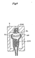
- a slit SL is made in a portion of the flange FL between the second zipper or the rib and the hermetically sealing zipper CH 1 at the position of the closing end E 2, thereby as illustrated on FIG. 9 , not allowing to form a closed plastic cylinder which is constituted of the flange portions connected to the second zipper or the rib and the hermetically sealing zipper in an engaged state at the closing end position of the hermetically sealing zipper. Consequently, since the top side of the flange is made mobile thereby even if widened by the opening plate, any force of opening the underside of the hermetically sealing plastic zipper is never generated, whereby hermetical sealability thereof can be maintained.
- the above-mentioned slit according to the present invention although seemingly resembles the slit or notch described in JP-C-3,026,839 , is fundamentally different therefrom in terms of its function. Specifically in the method in JP-C-3,026,839 , it is a prerequisite to open a rib at the end of a flange to open a zipper, and the significance of the existence for the slit or notch is not to allow the rib to open, or to disconnect the zipper therefrom even if the rib is opened.
- the rib at the end of the flange portion is not opened but is consistently closed at the time of opening the zipper or actuating the slit or notch, differently from the method in JP-C-3,026,839 .
- the slit or notch according to the present invention exists not to allow to form a closed plastic cylinder which is constituted by connecting the flexible flange portions, thereby rendering itself entirely different from that of said Patent in terms of its function and structure.
- the slit or notch as described in JP-A-503672 / 1998 (Heisei 10) is constituted such that a cantilever flange having rigidity and one opening fulcrum is installed on the opening side of the zipper, and is made into an inverse T-shaped separate structure so that the function of said separate structure is invalidated with the the slit or notch by opening the rigid cantilever flange at the time of opening a zipper.
- the zipper is opened by pushing the wedged opening plate into the inside of a closed plastic cylinder FP which has flexible flanges FL and is constituted by connecting the flange portions.
- the slit or notch according to the present invention exists not to allow to form a closed plastic cylinder, thereby rendering itself entirely different from that of JP-A-503672 / 1998 in terms of its function and structure.
- the slider to be used in the present invention is preferably a knocked-down slider.
- a knocked-down slider there is usable as a knocked-down slider, the slider as illustrated on FIG. 10 and FIG. 11 as disclosed in JP-A-130594 / 2001 .
- Such slider is fabricated by attaching the slider to a zipper in a state that a plate portion C - 1 equipped with an inside guide S - I is open and subsequently closing the plate portion C - 1.
- the slider to be used in order to carry out the present invention is preferably slider which is disclosed in JP-A-130594 / 2001 (Heisei 13) and which is assembled by closing the guide constituent member through a flexural axis perpendicular to a plane containing a bag body as illustrated on FIG. 10 and FIG. 11 .
- the depth L 4 of the connecting groove S 4 being larger enables the width of the opening plate S 1 to be smaller, and conversely the depth L 4 being smaller obliges the width S 1 to be larger.
- the width L 5 of the opening plate S 1 needs to be minimized and thus, the depth L 4 of the connecting groove S 4 is preferably as close as possible to (L-2 plus L 3).
- the maximum depth of the connecting groove S 4 is the sum of (L 2 plus L 3) and the thickness of the opening plate S 1, but depth of the connecting groove S 4 is usually smaller than the maximum depth thereof.
- the length of the rib L 2 in contact with the opening plate S 1 is preferably in the range of 60 to 150% of the width of the zipper L 1.
- the length of the rib L 2 when being larger than the range, leads to an unreasonably large slider, whereas the length, when being smaller than the range, brings about difficulty in closing the plate C - 1 as explained on FIG. 11 , thereby making it impossible to steadily assemble the hermetically sealing zipper while maintaining the engaged state thereof.
- L - LDPE linear low density polyethylene
- the average opening strength was 2.29 with a standard deviation of 0.39.
- the bag bodies in the same lot as above in 20 sheets were each equipped with the slider exemplified on FIG. 10 through FIG. 13 and disclosed in JP-A-130594 / 2001 , and were subjected to opening closing tests. As a result, all the bag bodies could be easily opened and closed.
- L - LDPE linear low density polyethylene
- the average opening strength was 3.90 with a standard deviation of 0.44.
- the bag bodies in the same lot as above in 20 sheets were each equipped with the slider same as in Comparative Example 1, and were subjected to opening closing tests.
- the average opening strength was 4.08 with a standard deviation of 0.47.
- the bag bodies in the same lot as above in 20 sheets were each equipped with the slider which had a cross sectional configuration as illustrated on FIG. 3 , and which was fitted with an opening plate having a width L 5 of 4 mm, a cover having a width of 1 mm and a connecting groove having a depth L 4 of 2 mm, and were subjected to opening closing tests.
- the slider which had a cross sectional configuration as illustrated on FIG. 3 , and which was fitted with an opening plate having a width L 5 of 4 mm, a cover having a width of 1 mm and a connecting groove having a depth L 4 of 2 mm, and were subjected to opening closing tests.
- the aforesaid slider is applicable to a zipper, even if it has a strong opening strength.
- the slider is imparted with an extremely high opening strength in spite of its being miniatured and thereby is capable of easily open a zipper in which hooks themselves or opening end edges themselves are bonded with easily peelable plastic layers for the purpose of preventing unjust unsealing and which has a strong opening strength.
Landscapes
- Engineering & Computer Science (AREA)
- Mechanical Engineering (AREA)
- Bag Frames (AREA)
- Slide Fasteners (AREA)
Claims (4)
- Fermeture à glissière en plastique fermant de manière étanche munie d'un coulisseau (S) par lequel la fermeture à glissière est ouverte et fermée, comprenant une première fermeture à glissière fermant de manière hermétique (CH1), ayant une paire de crochets mâles (M1-1 ; M1-2) et de crochets femelles (F1-1 ; F2-2) formée sur des films en plastique (F), la fermeture à glissière étant munie de brides (FL) sur les côtés de parties d'ouverture pour chacun des crochets mâles et des crochets femelles de celle-ci, et une deuxième fermeture à glissière fermant de manière hermétique (CH2) ou nervures de serrage (B) installées aux extrémités respectives des brides (FL), le coulisseau (S) comprend une plaque d'ouverture cunéiforme située entre la première fermeture à glissière et la deuxième fermeture à glissière ou les nervures, la plaque d'ouverture cunéiforme (S1), un étançon d'ouverture (S3) et une rainure de raccord (S4) située au-dessus de la plaque d'ouverture cunéiforme et le logement de la deuxième fermeture à glissière ou les nervures, la plaque d'ouverture cunéiforme (S1) l'étançon d'ouverture (S3), la rainure de raccord (S4), la première fermeture à glissière (CH1) et la deuxième fermeture à glissière (CH2) ou les nervures (B) fermant de manière hermétique sont positionnés respectivement de sorte que quand le coulisseau (S) coulisse vers une extrémité d'ouverture (E1), la plaque d'ouverture cunéiforme (S1) est pressée à l'intérieur d'un cylindre en plastique fermé (FP) qui est constitué des parties de brides (FL) dans un état de raccord aux extrémités des parties supérieures respectives de celui-ci et la première fermeture à glissière (CH1) dans un état de mise en prise, de sorte que la première fermeture à glissière (CH1) est la première ouverte, et une fois que la première fermeture à glissière (CH1) est ouverte, la deuxième fermeture à glissière (CH2) ou les nervures (B) n'est plus raccordée, par l'étançon d'ouverture.
- Fermeture à glissière selon la revendication 1, où une fente (SL) est prévue à une partie des brides (FL) correspondant à la plaque d'ouverture cunéiforme (S1) à la position de l'extrémité de fermeture (E2).
- Fermeture à glissière selon la revendication 1, où une partie de la deuxième fermeture à glissière (CH2) ou de la nervure (B), laquelle partie vient en contact avec la plaque d'ouverture cunéiforme (S1), est écrasée jusqu'à l'aplatir ou est découpée.
- Corps de sac agencé avec une fermeture à glissière en plastique fermant de manière étanche munie d'un coulisseau (S) selon l'une quelconque des revendications 1 à3.
Applications Claiming Priority (1)
| Application Number | Priority Date | Filing Date | Title |
|---|---|---|---|
| PCT/JP2001/007648 WO2003022697A1 (fr) | 2001-09-04 | 2001-09-04 | Fermeture a glissiere en plastique et corps de sac a fermeture en plastique |
Publications (3)
| Publication Number | Publication Date |
|---|---|
| EP1440898A1 EP1440898A1 (fr) | 2004-07-28 |
| EP1440898A4 EP1440898A4 (fr) | 2006-08-09 |
| EP1440898B1 true EP1440898B1 (fr) | 2009-12-09 |
Family
ID=11737700
Family Applications (1)
| Application Number | Title | Priority Date | Filing Date |
|---|---|---|---|
| EP01961349A Expired - Lifetime EP1440898B1 (fr) | 2001-09-04 | 2001-09-04 | Fermeture a glissiere en plastique et corps de sac a fermeture en plastique |
Country Status (6)
| Country | Link |
|---|---|
| US (1) | US6915546B2 (fr) |
| EP (1) | EP1440898B1 (fr) |
| JP (1) | JP4764599B2 (fr) |
| CN (1) | CN1257824C (fr) |
| DE (1) | DE60140771D1 (fr) |
| WO (1) | WO2003022697A1 (fr) |
Families Citing this family (43)
| Publication number | Priority date | Publication date | Assignee | Title |
|---|---|---|---|---|
| JP4540813B2 (ja) * | 2000-08-21 | 2010-09-08 | ハイパック株式会社 | プラスチックチャックのスライダー及びスライダー付き袋体並びにその袋体の製造方法 |
| US20030101552A1 (en) * | 2001-11-30 | 2003-06-05 | Plourde Eric P. | Variable alignment zipper for reclosable bags |
| FR2855153B1 (fr) * | 2003-05-19 | 2007-04-13 | S2F Flexico | Ensemble de fermeture pour sachet comprenant des moyens contre l'arrachement d'un curseur et sachet equipe |
| ATE407586T1 (de) * | 2003-11-21 | 2008-09-15 | Juichi Kasai | Herstellungsverfahren für kunststoffspannfutter mit hoher luftdichtheit und kunststoffspannfutter mit hoher luftdichtheit |
| US20060210201A1 (en) * | 2004-04-09 | 2006-09-21 | Ackerman Bryan L | Slider and closure mechanism for closure assembly |
| US7574781B2 (en) * | 2004-04-09 | 2009-08-18 | S.C. Johnson Home Storage, Inc. | Closure assembly with slider |
| US7850368B2 (en) * | 2004-06-04 | 2010-12-14 | S.C. Johnson & Son, Inc. | Closure device for a reclosable pouch |
| US7419300B2 (en) | 2004-06-16 | 2008-09-02 | S.C. Johnson Home Storage, Inc. | Pouch having fold-up handles |
| US7553082B2 (en) * | 2004-08-03 | 2009-06-30 | Illinois Tool Works Inc. | Evacuable storage bag having resealable means activated by slider |
| WO2006082593A1 (fr) * | 2005-02-03 | 2006-08-10 | Ashok Chaturvedi | Sac refermable avec securite enfants |
| US7162779B2 (en) * | 2005-02-16 | 2007-01-16 | Illinois Tool Works Inc. | Water-resistant zipper with slider |
| WO2006112035A1 (fr) * | 2005-03-31 | 2006-10-26 | Juichi Kasai | Mandrin en plastique avec piece coulissante et corps de sac avec le mandrin en plastique |
| FR2884227B1 (fr) * | 2005-04-08 | 2007-06-15 | S2F Flexico Sarl | Dispositif destine a la fermeture de sachets comprenant des moyens contre l'arrachement d'un curseur et sachet equipe |
| US20060269171A1 (en) * | 2005-05-26 | 2006-11-30 | Turvey Robert R | Slider with laterally displaceable engagement members |
| US7574782B2 (en) * | 2005-05-26 | 2009-08-18 | S.C. Johnson Home Storage, Inc. | Apparatus and method of operatively retaining an actuating member on an elongate closure mechanism |
| US7461434B2 (en) * | 2005-05-26 | 2008-12-09 | S.C. Johnson Home Storage, Inc. | Slider for closure assembly |
| US7496992B2 (en) * | 2005-07-01 | 2009-03-03 | Illinois Tool Works Inc. | Leakproof fastener with slider |
| CN101263001B (zh) * | 2005-09-13 | 2010-09-15 | 葛西寿一 | 具有防止不正当开封功能的塑料夹头及其制造方法和制造装置 |
| WO2007038465A1 (fr) * | 2005-09-27 | 2007-04-05 | Reynolds Consumer Products, Inc. | Emballage refermable et procede |
| US8714819B2 (en) | 2005-10-31 | 2014-05-06 | Global Packaging Solutions Limited | Reclosable fastener |
| US8256959B2 (en) * | 2006-06-14 | 2012-09-04 | Global Packaging Solutions Limited | Fastener strip, slider and reclosable container comprising same |
| US8096022B2 (en) * | 2005-10-31 | 2012-01-17 | Global Packaging Solutions Limited | Reclosable container and method of manufacture |
| US7946003B2 (en) * | 2005-11-01 | 2011-05-24 | Reynolds Consumer Products, Inc. | Package closure and method |
| JP2007176542A (ja) * | 2005-12-27 | 2007-07-12 | Showa Highpolymer Co Ltd | 電子部品用透明包装袋体 |
| GB0602741D0 (en) * | 2006-02-10 | 2006-03-22 | Unilever Plc | Fabric conditioning compositions |
| JP2007222435A (ja) * | 2006-02-24 | 2007-09-06 | Seisan Nipponsha:Kk | 合成樹脂製袋体用チャック及び合成樹脂製袋体 |
| US7610662B2 (en) * | 2006-11-15 | 2009-11-03 | Illinois Tool Works Inc. | Leakproof slider zipper |
| US7797802B2 (en) | 2007-11-29 | 2010-09-21 | S.C. Johnson & Son, Inc. | Actuating member for a closure assembly and method |
| US8245364B2 (en) * | 2008-04-23 | 2012-08-21 | S.C. Johnson & Son, Inc. | Closure mechanism having internal projections to decrease slider pull-off |
| US20120070103A1 (en) * | 2010-09-22 | 2012-03-22 | Coating Excellence International Llc | Bag and a method of manufacturing a bag |
| CN101947169B (zh) * | 2010-09-30 | 2011-11-23 | 烟台冰轮高压氧舱有限公司 | 一种软体舱充气性密封装置 |
| CN102894551B (zh) * | 2012-11-02 | 2015-08-05 | 宋致选 | 拉链组件及设置该拉链组件的保鲜袋 |
| JP5800844B2 (ja) * | 2013-03-13 | 2015-10-28 | 株式会社椿本チエイン | チューブ型ケーブル類保護案内装置 |
| US9950842B2 (en) * | 2014-06-20 | 2018-04-24 | S.C. Johnson & Son, Inc. | Multiple zipper slider bag |
| US9878828B2 (en) | 2014-06-20 | 2018-01-30 | S. C. Johnson & Son, Inc. | Slider bag with a detent |
| JP6953872B2 (ja) * | 2017-08-03 | 2021-10-27 | 大日本印刷株式会社 | ジッパーテープ |
| DE202017106084U1 (de) * | 2017-10-06 | 2019-01-10 | Cofresco Frischhalteprodukte Gmbh & Co. Kg | Verschlusseinrichtung für einen Beutel |
| CN108577109B (zh) * | 2018-07-17 | 2024-05-07 | 广东爱子优旺新材料有限公司 | 防止儿童打开的拉链袋 |
| CN111838901B (zh) * | 2019-04-30 | 2023-01-31 | 黄振正 | 夹链带 |
| US11565852B2 (en) * | 2019-10-09 | 2023-01-31 | William Buck | Garbage can retaining clip apparatus |
| CN112107085A (zh) * | 2020-10-29 | 2020-12-22 | 烟台白马包装有限公司 | 一种密封拉链、其滑块及密封袋 |
| JP7315808B1 (ja) * | 2021-11-10 | 2023-07-27 | 株式会社Oakインターナショナル | ポーチ |
| DE212023000355U1 (de) * | 2023-06-14 | 2025-07-02 | Thantawan Industry Public Company Limited | Vertraulicher Druckverschlussbeutel |
Family Cites Families (12)
| Publication number | Priority date | Publication date | Assignee | Title |
|---|---|---|---|---|
| US2637086A (en) * | 1950-08-31 | 1953-05-05 | Flexigrip Inc | Combined slide fastener |
| US5020194A (en) | 1990-03-07 | 1991-06-04 | Mobil Oil Corporation | Leakproof zipper with slider |
| JPH0677518A (ja) | 1992-08-26 | 1994-03-18 | Nec Corp | 半導体受光素子 |
| JP2529055Y2 (ja) * | 1993-04-19 | 1997-03-12 | 株式会社リヒトラブ | 袋体のスライダー |
| US5442837A (en) * | 1994-06-20 | 1995-08-22 | Mobil Oil Corporation | Integrated end stops for zipper slider |
| JP3430323B2 (ja) | 1995-02-15 | 2003-07-28 | 株式会社生産日本社 | 合成樹脂製袋体チャックのスライダー |
| JP2938784B2 (ja) | 1995-05-30 | 1999-08-25 | 昭和高分子株式会社 | プラスチックチャック |
| FR2761956B1 (fr) * | 1997-04-10 | 1999-06-25 | Flexico France Sarl | Sachet comportant des profiles de fermeture complementaires actionnes par curseur |
| JP2000152810A (ja) * | 1998-11-24 | 2000-06-06 | Ishizaki Shizai Kk | 開閉具及び該開閉具を備えたジッパー付き袋 |
| JP2001130594A (ja) | 1999-11-08 | 2001-05-15 | Showa Highpolymer Co Ltd | スライダー付きプラスチックチャック及び該プラスチックチャックを備えた袋体並びにその袋体の製造方法 |
| US7171730B2 (en) | 2000-11-13 | 2007-02-06 | Showa Highpolymer Co., Ltd. | Plastic chuck with highly airtight slider and bag body with the chuck |
| JP4559615B2 (ja) | 2000-12-11 | 2010-10-13 | ハイパック株式会社 | 不正開封を防止したスライダー付きプラスチックチャック及び該チャック付き袋体 |
-
2001
- 2001-09-04 CN CNB018164358A patent/CN1257824C/zh not_active Expired - Fee Related
- 2001-09-04 DE DE60140771T patent/DE60140771D1/de not_active Expired - Lifetime
- 2001-09-04 WO PCT/JP2001/007648 patent/WO2003022697A1/fr not_active Ceased
- 2001-09-04 US US10/381,436 patent/US6915546B2/en not_active Expired - Lifetime
- 2001-09-04 JP JP2003526782A patent/JP4764599B2/ja not_active Expired - Fee Related
- 2001-09-04 EP EP01961349A patent/EP1440898B1/fr not_active Expired - Lifetime
Also Published As
| Publication number | Publication date |
|---|---|
| US6915546B2 (en) | 2005-07-12 |
| US20040010893A1 (en) | 2004-01-22 |
| JPWO2003022697A1 (ja) | 2004-12-24 |
| CN1466534A (zh) | 2004-01-07 |
| JP4764599B2 (ja) | 2011-09-07 |
| EP1440898A4 (fr) | 2006-08-09 |
| EP1440898A1 (fr) | 2004-07-28 |
| DE60140771D1 (de) | 2010-01-21 |
| WO2003022697A1 (fr) | 2003-03-20 |
| CN1257824C (zh) | 2006-05-31 |
Similar Documents
| Publication | Publication Date | Title |
|---|---|---|
| EP1440898B1 (fr) | Fermeture a glissiere en plastique et corps de sac a fermeture en plastique | |
| US7165292B2 (en) | Plastic chuck with wrong opening preventing slider, and bag with the chuck | |
| US6293701B1 (en) | Resealable closure mechanism having slider device and methods | |
| US6009603A (en) | Closure fastener strips for resealable plastic film pouches | |
| US7171730B2 (en) | Plastic chuck with highly airtight slider and bag body with the chuck | |
| US6112374A (en) | Zipper for slider package | |
| KR100968995B1 (ko) | 척 부착 밀봉 백 | |
| KR20000069253A (ko) | 플라스틱 지퍼 백의 다층 핀 | |
| US20090042707A1 (en) | Reclosable storage bag closure with internal valving | |
| EP1300341A1 (fr) | Fermeture à glissière préscellée | |
| WO2004043812A1 (fr) | Mecanisme de fermeture etanche pour sac refermable | |
| US20090139067A1 (en) | Actuating member for a closure assembly and method | |
| MXPA01009533A (es) | Arreglo de cierre sujetador para empaques flexibles. | |
| JP2001072087A (ja) | 再閉鎖可能ジッパ組立体、再閉鎖可能なパッケージ、キャリアウェブ、および再閉鎖可能なパッケージを形成する形成方法 | |
| JP2006526551A (ja) | 使い捨て式容器 | |
| KR920017594A (ko) | 개폐식 플래스틱 패스너용 단부 클램프 스톱 | |
| EP1761438A2 (fr) | Fermeture anti-fuites a ressort | |
| US6874937B2 (en) | Reclosable packaging having slider-operated zipper with tamper-evident membrane | |
| EP2093153A1 (fr) | Corps de sac en résine synthétique avec une fonction d'ouverture facile | |
| EP2190752A2 (fr) | Systèmes de fermeture scellable et pièces dudit système | |
| JP2003226394A (ja) | マスクケース | |
| EP1139810B1 (fr) | Mecanisme de fermeture liberable comprenant un dispositif de glissiere et procedes associes | |
| JP4234415B2 (ja) | スライダー付きプラスチックチャックおよびチャック付き袋体 | |
| JP3117351U (ja) | チャックテープ | |
| JP2009131369A (ja) | 合成樹脂製チャックテープ |
Legal Events
| Date | Code | Title | Description |
|---|---|---|---|
| PUAI | Public reference made under article 153(3) epc to a published international application that has entered the european phase |
Free format text: ORIGINAL CODE: 0009012 |
|
| 17P | Request for examination filed |
Effective date: 20030221 |
|
| AK | Designated contracting states |
Kind code of ref document: A1 Designated state(s): AT BE CH CY DE DK ES FI FR GB GR IE IT LI LU MC NL PT SE TR |
|
| AX | Request for extension of the european patent |
Extension state: AL LT LV MK RO SI |
|
| A4 | Supplementary search report drawn up and despatched |
Effective date: 20060706 |
|
| RAP1 | Party data changed (applicant data changed or rights of an application transferred) |
Owner name: HIPACK CO., LTD. |
|
| 17Q | First examination report despatched |
Effective date: 20080616 |
|
| GRAP | Despatch of communication of intention to grant a patent |
Free format text: ORIGINAL CODE: EPIDOSNIGR1 |
|
| GRAS | Grant fee paid |
Free format text: ORIGINAL CODE: EPIDOSNIGR3 |
|
| GRAA | (expected) grant |
Free format text: ORIGINAL CODE: 0009210 |
|
| AK | Designated contracting states |
Kind code of ref document: B1 Designated state(s): DE FR GB IT |
|
| REG | Reference to a national code |
Ref country code: GB Ref legal event code: FG4D |
|
| REF | Corresponds to: |
Ref document number: 60140771 Country of ref document: DE Date of ref document: 20100121 Kind code of ref document: P |
|
| RAP2 | Party data changed (patent owner data changed or rights of a patent transferred) |
Owner name: HIPACK CO., LTD. |
|
| PLBE | No opposition filed within time limit |
Free format text: ORIGINAL CODE: 0009261 |
|
| STAA | Information on the status of an ep patent application or granted ep patent |
Free format text: STATUS: NO OPPOSITION FILED WITHIN TIME LIMIT |
|
| 26N | No opposition filed |
Effective date: 20100910 |
|
| REG | Reference to a national code |
Ref country code: FR Ref legal event code: PLFP Year of fee payment: 16 |
|
| REG | Reference to a national code |
Ref country code: FR Ref legal event code: PLFP Year of fee payment: 17 |
|
| REG | Reference to a national code |
Ref country code: FR Ref legal event code: PLFP Year of fee payment: 18 |
|
| PGFP | Annual fee paid to national office [announced via postgrant information from national office to epo] |
Ref country code: IT Payment date: 20190925 Year of fee payment: 19 Ref country code: DE Payment date: 20190918 Year of fee payment: 19 Ref country code: FR Payment date: 20190925 Year of fee payment: 19 |
|
| PGFP | Annual fee paid to national office [announced via postgrant information from national office to epo] |
Ref country code: GB Payment date: 20190920 Year of fee payment: 19 |
|
| REG | Reference to a national code |
Ref country code: DE Ref legal event code: R119 Ref document number: 60140771 Country of ref document: DE |
|
| GBPC | Gb: european patent ceased through non-payment of renewal fee |
Effective date: 20200904 |
|
| PG25 | Lapsed in a contracting state [announced via postgrant information from national office to epo] |
Ref country code: DE Free format text: LAPSE BECAUSE OF NON-PAYMENT OF DUE FEES Effective date: 20210401 Ref country code: FR Free format text: LAPSE BECAUSE OF NON-PAYMENT OF DUE FEES Effective date: 20200930 |
|
| PG25 | Lapsed in a contracting state [announced via postgrant information from national office to epo] |
Ref country code: GB Free format text: LAPSE BECAUSE OF NON-PAYMENT OF DUE FEES Effective date: 20200904 |
|
| PG25 | Lapsed in a contracting state [announced via postgrant information from national office to epo] |
Ref country code: IT Free format text: LAPSE BECAUSE OF NON-PAYMENT OF DUE FEES Effective date: 20200904 |