EP1441019A1 - Panneau pour la conversion d'images obtenues par rayonnement - Google Patents
Panneau pour la conversion d'images obtenues par rayonnement Download PDFInfo
- Publication number
- EP1441019A1 EP1441019A1 EP03028917A EP03028917A EP1441019A1 EP 1441019 A1 EP1441019 A1 EP 1441019A1 EP 03028917 A EP03028917 A EP 03028917A EP 03028917 A EP03028917 A EP 03028917A EP 1441019 A1 EP1441019 A1 EP 1441019A1
- Authority
- EP
- European Patent Office
- Prior art keywords
- photostimulable phosphor
- film
- group
- panel
- formula
- Prior art date
- Legal status (The legal status is an assumption and is not a legal conclusion. Google has not performed a legal analysis and makes no representation as to the accuracy of the status listed.)
- Withdrawn
Links
Images



Classifications
-
- G—PHYSICS
- G21—NUCLEAR PHYSICS; NUCLEAR ENGINEERING
- G21K—HANDLING OF PARTICLES OR IONISING RADIATION NOT OTHERWISE PROVIDED FOR; IRRADIATION DEVICES; GAMMA RAY OR X-RAY MICROSCOPES
- G21K4/00—Conversion screens for the conversion of the spatial distribution of X-rays or particle radiation into visible images, e.g. fluoroscopic screens
-
- C—CHEMISTRY; METALLURGY
- C09—DYES; PAINTS; POLISHES; NATURAL RESINS; ADHESIVES; COMPOSITIONS NOT OTHERWISE PROVIDED FOR; APPLICATIONS OF MATERIALS NOT OTHERWISE PROVIDED FOR
- C09K—MATERIALS FOR MISCELLANEOUS APPLICATIONS, NOT PROVIDED FOR ELSEWHERE
- C09K11/00—Luminescent materials, e.g. electroluminescent or chemiluminescent
- C09K11/08—Luminescent materials, e.g. electroluminescent or chemiluminescent containing inorganic luminescent materials
- C09K11/62—Luminescent materials, e.g. electroluminescent or chemiluminescent containing inorganic luminescent materials containing gallium, indium or thallium
- C09K11/626—Halogenides
- C09K11/628—Halogenides with alkali or alkaline earth metals
-
- C—CHEMISTRY; METALLURGY
- C09—DYES; PAINTS; POLISHES; NATURAL RESINS; ADHESIVES; COMPOSITIONS NOT OTHERWISE PROVIDED FOR; APPLICATIONS OF MATERIALS NOT OTHERWISE PROVIDED FOR
- C09K—MATERIALS FOR MISCELLANEOUS APPLICATIONS, NOT PROVIDED FOR ELSEWHERE
- C09K11/00—Luminescent materials, e.g. electroluminescent or chemiluminescent
- C09K11/08—Luminescent materials, e.g. electroluminescent or chemiluminescent containing inorganic luminescent materials
- C09K11/77—Luminescent materials, e.g. electroluminescent or chemiluminescent containing inorganic luminescent materials containing rare earth metals
- C09K11/7715—Luminescent materials, e.g. electroluminescent or chemiluminescent containing inorganic luminescent materials containing rare earth metals containing cerium
- C09K11/7719—Halogenides
- C09K11/772—Halogenides with alkali or alkaline earth metals
-
- C—CHEMISTRY; METALLURGY
- C09—DYES; PAINTS; POLISHES; NATURAL RESINS; ADHESIVES; COMPOSITIONS NOT OTHERWISE PROVIDED FOR; APPLICATIONS OF MATERIALS NOT OTHERWISE PROVIDED FOR
- C09K—MATERIALS FOR MISCELLANEOUS APPLICATIONS, NOT PROVIDED FOR ELSEWHERE
- C09K11/00—Luminescent materials, e.g. electroluminescent or chemiluminescent
- C09K11/08—Luminescent materials, e.g. electroluminescent or chemiluminescent containing inorganic luminescent materials
- C09K11/77—Luminescent materials, e.g. electroluminescent or chemiluminescent containing inorganic luminescent materials containing rare earth metals
- C09K11/7728—Luminescent materials, e.g. electroluminescent or chemiluminescent containing inorganic luminescent materials containing rare earth metals containing europium
- C09K11/7732—Halogenides
- C09K11/7733—Halogenides with alkali or alkaline earth metals
Definitions
- the present invention relates to a radiographic image conversion panel.
- a radiographic image conversion panel provided with a photostimulable phosphor layer on a support has been developed for a method for imaging a radiological image without using a silver salt in order to obtain a radiographic image.
- a radiation ray transmitted through a subject is applied to a photostimulable phosphor layer, the radiographic energy corresponding to the radiation transmittance in each part of the subject is accumulated in a photostimulable phosphor, thereafter, the photostimulable phosphor is time-serially excited with an electromagnetic wave (an excitation light) such as a visible ray or an infrared ray to thereby discharge the radiographic energy accumulated in the photostimulable phosphor as photostimulated luminescence and then, a signal due to the strength and weakness of this light is, for example, photoelectrically transferred to obtain an electric signal and the signal is reproduced on recording materials such as a silver halide photographic sensitive material or a display apparatus such as a CRT as a visible image.
- an electromagnetic wave an excitation light
- a signal due to the strength and weakness of this light is, for example, photoelectrically transferred to obtain an electric signal and the signal is reproduced on recording materials such as a silver halide photographic sensitive material or a display apparatus
- radiographic image conversion panels using the photostimulable phosphor can be repeatedly used because after accumulating radiographic image information, the accumulated energy is discharged by scanning of excitation light, so that a radiographic image can be again accumulated after the scanning.
- a radiographic film is spent for each shooting, on the other hand, in this radiographic image conversion method, the radiographic image conversion panel is repeatedly used and therefore, this method is advantageous in terms of resource conservation or economic efficiency.
- Such a radiographic image conversion panel is also used in an X ray image diagnostic apparatus or the like for medical use in many cases.
- a radiographic image conversion panel having higher sensitivity and sharpness is demanded, particularly, in order to reduce the exposed dose of radiation rays irradiated to a patient.
- the thickness of a phosphor layer is made to be in a range of from 300 to 700 ⁇ m and the relative density thereof is made to be in a range of from 85 to 97% in the patent document 1 (Japanese Patent Laid-Open Publication No.2002-214397 (page 2)).
- a radiation ray transmitted through a subject is applied to a photostimulable phosphor layer, the radiographic energy corresponding to the radiation transmittance in each part of the subject is accumulated in the photostimulable phosphor layer to form a latent image (an accumulated image), thereafter, the photostimulable phosphor layer is scanned with a photostimulated excitation light (a laser beam is used) , thereby, the radiographic energy accumulated in each part is emitted and converted into a light, and the strength and weakness of this light is read out to obtain an image.
- This image may be reproduced on various displays such as a CRT or the like, or may be reproduced as a hardcopy.
- the photostimulable phosphor layer of the radiographic image conversion panel used for this radiographic image conversion method for example, there is a method for using a photostimulable phosphor layer having a fine quasi-columnar block formed by depositing a photostimulable phosphor on a support having a fine concavoconvex pattern, as performed in Japanese Patent Laid-Open Publication No. Sho 61-142497, etc.
- a method for using a radiographic image conversion panel having a photostimulable phosphor layer in which cracks between columnar blocks obtained by depositing a photostimulable phosphor on a support having a fine pattern are shock-treated to be further developed as described in Japanese Patent Laid-Open Publication No. Sho 61-142500
- a method for using a quasi-columnar radiographic image conversion panel in which cracks are caused from the surface side of a photostimulable phosphor layer formed on a face of a support as described in Japanese Patent Laid-Open Publication No.
- Sho 62-39737 furthermore, a method for providing cracks by forming a photostimulable phosphor layer having a void on an upper face of a support according to deposition, and thereafter, by growing the void according to heat treatment as described in Japanese Patent Laid-Open Publication No. Sho 62-110200, and the like are suggested.
- Japanese Patent Laid-Open Publication No. Hei 2-58000 proposes a radiographic image conversion panel having a photostimulable phosphor layer in which an elongated columnar crystal having a constant slope to a normal line direction of a support is formed on the support according to a vapor phase deposition method.
- any of these attempts of controlling a shape of the photostimulable phosphor layer is characterized in that since the transversal diffusion of photostimulated excitation light (or photostimulated luminescence) can be suppressed by rendering the photostimulable phosphor layer columnar (the light reaches the support face while repeating reflection in a crack (a columnar crystal) interface), the sharpness of an image formed by the photostimulated luminescence can be noticeably increased.
- a photostimulable phosphor crystal formed by the above-described vapor phase deposition method particularly has high hygroscopicity in materials or is not protected by a binder and therefore, when it is used, an improvement effect is confirmed but is insufficient with a sealing method using a moisture-proof protective film where a thin film of metal oxide or the like is deposited as described above. Accordingly, a method for more completely preventing moisture absorption is demanded.
- the patent document 2 Japanese Patent Laid-Open Publication No. 2001-2355478 describes an example of using a laminated film where a polyparaxylylene film and a moisture-proof film of silica or the like are sequentially formed by a CVD method in order to protect a phosphor such as CsI which is a scintillator material, against vapor.
- a phosphor such as CsI which is a scintillator material
- the present invention has been made under these circumstances and a first object of the present invention is to provide a radiographic image conversion panel having more excellent luminescence luminance.
- a second object of the present invention is to provide a radiographic image conversion panel capable of being used in a preferable state for a long period of time by reducing moisture permeability to a photostimulable phosphor layer formed by a vapor phase growth method and completely sealing the radiographic image conversion panel.
- a first aspect of the present invention is a radiographic image conversion panel having a photostimulable phosphor layer on a support, wherein a photostimulable phosphor is formed on the support by a vapor phase deposition method and then, heat treatment is performed at a temperature of from 80°C to 300°C.
- the above-described heat treatment is preferably performed at a temperature of from 100 °C to 200 °C.
- the above-described photostimulable phosphor layer preferably comprises a photostimulable phosphor represented by a following Formula (1): Formula (1) M 1 X ⁇ aM 2 X' 2 ⁇ bM 3 X" 3 :eA wherein the M 1 is at least one kind of alkali metal selected from a group consisting of Li, Na, K, Rb and Cs, the M 2 is at least one kind of bivalent metal selected from a group consisting of Be, Mg, Ca, Sr, Ba, Zn, Cd, Cu and Ni, the M 3 is at least one kind of trivalent metal selected from a group consisting of Sc, Y, La, Ce, Pr, Nd, Pm, Sm, Eu, Gd, Tb, Dy, Ho, Er, Tm, Yb, Lu, Al, Ga and In, each of the X, the X' and the X" is at least one kind of halogen selected from a group consisting of F, Cl, Br and I, the A is at least one kind of
- the M 1 in Formula (1) is preferably at least one kind of alkali metal selected from a group consisting of K, Rb and Cs.
- the X in Formula (1) is preferably at least one kind of halogen selected from a group consisting of Br and I.
- the M 2 in Formula (1) is preferably at least one kind of bivalent metal selected from a group consisting of Be, Mg, Ca, Sr and Ba.
- the M 3 in Formula (1) is preferably at least one kind of trivalent metal selected from a group consisting of Y, La, Ce, Sm, Eu, Gd, Lu, Al, Ga and In.
- the b in Formula (1) preferably represents a numeric value in a range of 0 ⁇ b ⁇ 10 -2 .
- the A in Formula (1) is preferably at least one kind of metal selected from a group consisting of Eu, Cs, Sm, Tl and Na.
- the above-described photostimulable phosphor layer preferably comprises a columnar crystal of the above-described photostimulable phosphor.
- the above-described columnar crystal preferably comprises a photostimulable phosphor represented by the following Formula (2): Formula (2) CsX: A wherein the X represents Br or I, and the A represents Eu, In, Ga or Ce.
- the radiographic image conversion panel having more excellent luminescence luminance can be obtained.
- a radiographic image conversion panel comprises: a support; a photostimulable phosphor layer formed on the support by vapor phase deposition to a film thickness of 50 ⁇ m or more; an organic film integrally deposited and formed to cover a surface of a photostimulable phosphor of the photostimulable phosphor layer; and a metal oxide-deposited film covering at least a side of the photostimulable phosphor layer.
- the organic film is preferably a polyparaxylylene film.
- the photostimulable phosphor is preferably represented by the following Formula (1): Formula (1) M 1 X ⁇ aM 2 X 2 ' ⁇ bM 3 X 3 ":eA wherein the M 1 is at least one kind of alkali metal selected from a group consisting of Li, Na, K, Rb and Cs, the M 2 is at least one kind of divalent metal selected from a group consisting of Be, Mg, Ca, Sr, Ba, Zn, Cd, Cu and Ni, the M 3 is at least one kind of trivalent metal selected from a group consisting of Sc, Y, La, Ce, Pr, Nd, Pm, Sm, Eu, Gd, Tb, Dy, Ho, Er, Tm, Yb, Lu, Al, Ga and In, each of the X, the X' and the X" is at least one kind of halogen atom selected from a group consisting of F, Cl, Br and I, the A is at least one kind of metal selected from a group consisting of Eu, Tb,
- the M 1 in Formula (1) is preferably at least one kind of alkali metal selected from a group consisting of K, Rb and Cs.
- the X in Formula (1) is preferably at least one kind of halogen atom selected from a group consisting of Br and I.
- the M 2 in Formula (1) is preferably at least one kind of bivalent metal selected from a group consisting of Be, Mg, Ca, Sr and Ba.
- the M 3 in Formula (1) is preferably at least one kind of trivalent metal selected from a group consisting of Y, Ce, Sm, Eu, Al, La, Gd, Lu, Ga and In.
- the b in Formula (1) is preferably in a range of 0 ⁇ b ⁇ 10 -2 .
- the A in Formula (1) is preferably at least one kind of metal selected from a group consisting of Eu, Cs, Sm, Tl and Na.
- the photostimulable phosphor preferably comprises a columnar crystal.
- the columnar crystal preferably comprises a photostimulable phosphor represented by the following Formula (2) as a main component, Formula (2) CsX: A wherein the X represents Br or I, and A represents Eu, In, Ga or Ce.
- a radiographic image conversion panel improved in moisture-proof property without reducing image quality such as sharpness and the like can be obtained. Therefore, a radiographic image conversion panel having a long life period, that is, capable of being used in a preferable state for a long period of time can be provided.
- a photostimulable phosphor layer 12 comprising columnar crystals 13 of a photostimulable phosphor and a void 14 formed among the columnar crystals 13 is formed on the whole surface of a support 11 in a thickness of 50 ⁇ m or more, preferably from 300 to 500 ⁇ m by a vapor phase deposition method and a protective layer for protecting the photostimulable phosphor layer is provided according to need.
- a resin impregnated carbon fiber (a carbon fiber reinforced resin) can be used and specific examples of the carbon fiber include a commercially available carbon fiber (an epoxy resin impregnated carbon fiber, #132, produced by Toho Rayon Co., Ltd.).
- a material having thermal resistance can be arbitrarily selected from commonly known materials.
- a quarts glass sheet, a metal sheet comprising aluminum, iron, tin and chrome, etc. and a resin sheet comprising aramid, etc., or a sheet in combination thereof can be used.
- Formula (1) M 1 X ⁇ aM 2 X 2 ' ⁇ bM 3 X 3 ":eA
- the M 1 is at least one kind of alkali metal selected from a group consisting of Li, Na, K, Rb and Cs, particularly preferably at least one kind of alkali metal selected from a group consisting of K, Rb and Cs.
- the M 2 is at least one kind of divalent metal selected from a group consisting of Be, Mg, Ca, Sr, Ba, Zn, Cd, Cu and Ni, particularly preferably at least one kind of divalent metal selected from a group consisting of Be, Mg, Ca, Sr and Ba.
- the M 3 is at least one kind of trivalent metal selected from a group consisting of Sc, Y, La, Ce, Pr, Nd, Pm, Sm, Eu, Gd, Tb, Dy, Ho, Er, Tm, Yb, Lu, Al, Ga and In, particularly preferably at least one kind of trivalent metal selected from a group consisting of Y, La, Ce, Sm, Eu, Gd, Lu, Al, Ga and In.
- Each of the X, the X' and the X" is at least one kind of halogen selected from a group consisting of F, Cl, Br and I, the X is particularly preferably at least one kind of halogen selected from a group consisting of Br and I.
- the A is at least one kind of metal selected from a group consisting of Eu, Tb, In, Ga, Cs, Ce, Tm, Dy, Pr, Ho, Nd, Yb, Er, Gd, Lu, Sm, Y, Tl, Na, Ag, Cu and Mg, particularly preferably at least one kind of metal selected from a group consisting of Eu, Cs, Sm, Tl and Na.
- Each of the a, the b and the e represents a numeric value in a range of 0 ⁇ a ⁇ 0.5, 0 ⁇ b ⁇ 0.5 and 0 ⁇ e ⁇ 0.2, and the b particularly preferably represents a numeric value in a range of 0 ⁇ b ⁇ 10 -2 .
- the above-described columnar crystal 13 preferably has a photostimulable phosphor represented by the following Formula (2) : Formula (2) CsX: A wherein the X represents Br or I, and the A represents Eu, In, Ga or Ce.
- the above-described photostimulable phosphor is manufactured by a manufacturing method described below, for example, using the following phosphor raw materials of (a) to (d):
- the phosphor raw materials in the above-described (a) to (d) are weighed so as to satisfy each range of the a, the b and the e of Formula (1) , and are mixed with pure water. In this case, they may be mixed sufficiently by using a mortar, ball mill, mixer mill or the like.
- the obtained raw material mixture is filled in a heat-proof container such as a quartz crucible, an alumina crucible or the like, and calcining is performed in an electric furnace.
- the calcining temperature is preferably from 500 to 1000°C.
- the calcining time differs according to the filling amount, calcining temperature and the like of the raw material mixture, however, preferably from 0.5 to 6 hours.
- mild reducing atmosphere such as nitrogen gas atmosphere including a small amount of hydrogen gas, carbon acid gas atmosphere including a small amount of carbon monoxide, and the like; neutral atmosphere such as nitrogen gas atmosphere, argon gas atmosphere and the like; or mild oxidizing atmosphere including a small amount of oxygen gas is preferable.
- the calcined material is taken out from the electric furnace to be crushed. Thereafter, the powders of the calcined material are again filled in the heat-proof container, are put into the electric furnace, and if re-calcining is performed with the same calcining conditions as above, the luminescence luminance of photostimulable phosphor can be made higher. Further, in case of cooling the calcined material from the calcining temperature to room temperature, a desired photostimulable phosphor can also be obtained by taking the calcined material out of the electric furnace and cooling it in air. However, it may be cooled under remaining mild reducing atmosphere, neutral atmosphere or mild oxidizing atmosphere which is the same as at the time of calcining.
- the luminescence luminance of the obtained photostimulable phosphor according to stimulation can be made further higher by making the calcined material move from a heating section to a cooling section in the electric furnace, and by cooling it rapidly under mild reducing atmosphere, neutral atmosphere or mild oxidizing atmosphere.
- a photostimulable phosphor layer is formed by using a vapor phase deposition method where the above-described photostimulable phosphor is deposited on one surface of the support 11.
- a deposition method As the vapor phase deposition method, a deposition method, sputtering method, CVD method, ion plating method and the like can be used.
- a support is placed in a deposition apparatus, and air in the deposition apparatus is discharged so as to obtain a degree of vacuum of approximately 1. 333 ⁇ 10 -4 Pa.
- At least one of the above-described photostimulable phosphors is heated and evaporated by a method such as resistive heating, electron beam method or the like, and the photostimulable phosphor is grown to a desired thickness on the surface of the support.
- a photostimulable phosphor layer without containing a binder is formed.
- a support is placed in a sputtering apparatus, and air in the apparatus is discharged so as to obtain a degree of vacuum of approximately 1.333 ⁇ 10 -4 Pa.
- inert gas such as Ar, Ne or the like is introduced into the sputtering apparatus as gas for sputtering, and a gas pressure is made to approximately 1.333 ⁇ 10 -1 Pa.
- sputtering is performed by using the photostimulable phosphor as a target, and the photostimulable phosphor layer is grown to a desired thickness on the support.
- the film thickness of the photostimulable phosphor layer changes according to the intended use of the radiographic image conversion panel or according to the types of the photostimulable phosphor, however, 50 ⁇ m or more, preferably, from 300 to 500 ⁇ m.
- the temperature of the support on which the photostimulable phosphor layer is formed is preferably set to 50°C to 400°C. It is preferably 100°C to 250°C in terms of characteristics of the phosphor. In the case of using a resin as a support, it is preferably 50°C to 150°C, more preferably 50°C to 100°C in consideration of heat resistance of the resin.
- FIG. 2 is a view showing a state where the photostimulable phosphor layer 12 is formed on the support by the deposition. Assuming that an incident angle of a photostimulable phosphor steam flow 16 to the normal line direction (R) of the support 11 face fixed on a support holder 15 is ⁇ 2 (60 degrees in the figure) and an angle of the formed columnar crystal 13 to the normal line direction (R) of the support face is ⁇ 1 (30 degrees in the figure), experientially the ⁇ 1 becomes about half of the ⁇ 2 and the columnar crystal 13 is formed at this angle.
- a filling material such as a binder or the like may be filled in voids 14 formed among columnar crystals 13.
- materials of reinforcement of the photostimulable phosphor layer 12 materials having high optical absorption and materials having high optical reflectance may be filled. Thereby, the reinforcement effect can be obtained, and moreover, it is effective to reduce optical dispersion in the transverse direction of the photostimulated excitation light which entered the photostimulable phosphor layer 12.
- the growth rate of the photostimulable phosphor layer in the above-described vapor phase deposition method is preferably from 0.05 ⁇ m/min to 300 ⁇ m/min.
- the productivity of the radiographic image conversion panel becomes poor, so that it is not preferable.
- the growth rate exceeds 300 ⁇ m/min, it becomes difficult to control the growth rate, so that it is not preferable.
- the present invention is characterized in that heat treatment is performed at a high temperature, to the radiographic image conversion panel having the photostimulable phosphor layer formed by using the above-described vapor phase deposition method.
- the heat treatment is performed at from 80°C to 300°C, more preferably, from 100°C to 200°C.
- the heat-treating time depends on a temperature, however, the heat treatment is preferably performed for from 1 to 10,000 min. It is preferable that the heat treatment is performed for approximately from 1, 000 to 2, 000 min at 100°C, and for approximately from 20 to 30 min at 200°C.
- the heat treatment method is not particularly limited, and any method may be used as long as a temperature-controlled room is used where the support having formed thereon the photostimulable phosphor layer can be perfectly stored and a temperature and humidity can be controlled.
- a protective layer is provided to the opposite side of the side of the support where the photostimulable phosphor layer is formed, according to need.
- the protective layer may be formed by applying application liquid for a protective layer directly on the surface of the photostimulable phosphor layer, or a protective layer formed separately beforehand may be adhered to the photostimulable phosphor layer.
- a regular material for protective layer such as cellulose acetate, nitrocellulose, polymethyl methacrylate, polyvinyl butyral, polyvinyl formal, polycarbonate, polyester, polyethylene terephthalate, polyethylene, polyvinylidene chloride, nylon, polytetrafluoroethylene, polytrifluoro-ethylene chloride, tetrafluoroethylene-hexafluoropropylene copolymer, vinylidene chloride-vinyl chloride copolymer, vinylidene chloride-acrylonitrile copolymer or the like is used.
- a transparent glass substrate can be used as a protective layer.
- the protective layer may be formed by laminating inorganic materials such as SiC, SiO 2 , SiN, Al 2 O 3 and the like by a deposition method, a sputtering method or the like.
- the layer thickness of these protective layers is, preferably, from 0.1 to 2,000 ⁇ m.
- a carbon fiber (#132, produced by Toho Rayon Co., Ltd.) having a film thickness of 1 mm at a carrier speed of 1.0 m/min
- a pressure of 4.9 ⁇ 10 N/cm 2 was applied to a carrier heat roll to obtain a substrate as a support.
- a photostimulable phosphor (CsBr:Eu) was deposited to form a photostimulable phosphor layer.
- the distance between the support and a slit was made to be 60 cm. Then, by using a slit made of aluminum, deposition was performed by carrying the substrate toward the direction parallel to the longitudinal direction of the substrate so as to obtain a photostimulable phosphor layer having a thickness of 300 ⁇ m.
- the support was placed in a deposition apparatus. Then, press molding was performed by using the phosphor raw material (CsBr:Eu) as the evaporation source, and the support was charged in a water-cooled crucible.
- the phosphor raw material CsBr:Eu
- the air inside of the deposition apparatus was once discharged, and N 2 gas was introduced.
- the degree of vacuum was adjusted to 0.133 Pa, the photostimurable phosphor layer was deposited by keeping the temperature of the support at from 50°C to 100°C. The deposition was terminated when the film thickness of the photostimulable phosphor layer became 500 ⁇ m.
- the photostimulable phosphor layer was heat treated with the support at each temperature of 80°C, 100°C, 150°C, 200°C, 300°C and 400°C in dry air or N 2 atmosphere.
- the luminance was evaluated by using the Regius 350 produced by Konica Corporation.
- the amount of light emitted from each radiographic image conversion panel sample after irradiating an X-ray was measured and compared with the amount of light emitted from the radiographic image conversion panel sample not heat treated.
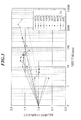
- FIG. 3 shows the heat treatment temperature and time, and changes of luminance.
- a sample heat treated in an air atmosphere at 80°C for 60 min showed the luminance as high as 1.1 times that of a sample not heat treated. Further, a sample heat treated in an air atmosphere at 80°C for 1,000 min showed the luminance as high as 1.4 times that of a sample not heat treated.
- a sample heat treated in an air atmosphere at 100°C for 1,000 min showed the luminance as high as 1.8 times that of a sample not heat treated, however, a sample heat treated for 2,000 min was reduced in the luminance.
- a sample heat treated in an air atmosphere at 150°C for 20 min showed the luminance as high as 1.6 times that of a sample not heat treated, however, a sample heat treated for 40 min was reduced in the luminance.
- a sample heat treated in an air atmosphere at 200°C for 5 min showed the luminance as high as 1.3 times that of a sample not heat treated.
- a sample heat treated in an air atmosphere at 200°C for 20 min showed the luminance as high as 1.6 times that of a sample not heat treated, however, a sample heat treated for 60 min was reduced in the luminance and showed the luminance as high as 1.4 times that of a sample not heat treated.
- a sample heat treated in an air atmosphere at 300°C for 2.5 min showed the luminance as high as 1.2 times that of a sample not heat treated, however, when the sample was heat treated for 5 min or more, the luminance was lowered.
- a sample heat treated at a temperature of from 80°C to 300°C after forming a photostimulable phosphor on a support by a vapor phase deposition method is increased in the luminance as compared with a sample not heat treated.
- the present invention is that on a surface of a photostimulable phosphor layer where a photostimulable phosphor is formed on a support in a film thickness of 50 ⁇ m or more by a vapor phase deposition, an organic film having high water repellency is deposited and formed integrally with the support so as to cover the surface of the layer and then, the photostimulable phosphor layer and support having the organic film are sealed so as to integrally cover themby using a metal oxide-deposited film, whereby a radiographic image conversion panel having high moisture-proof property is obtained.
- a photostimulable phosphor layer and a support are sealed by covering them with a moisture-proof protective film to prevent invasion of moisture.
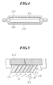
- a support 112 having a photostimulable phosphor layer 111 is integrally covered with a moisture-proof protective films 113 and 114 comprising a metal oxide-deposited resin film so as to seal the layer against moisture.
- a means of increasing the number of films where a metal oxide such as silica or alumina is deposited, or a means of increasing the film thickness of the metal oxide film in order to enhance moisture-proof property causes reduction in sharpness. Accordingly, a method for improving moisture-proof property without causing reduction in image quality such as sharpness is required. Further, as a source of gradually accelerating the deterioration in performance of a radiographic image conversion panel, it is considered that the surface of a photostimulable phosphor columnar crystal formed by a vapor phase deposition method is not actually smooth and also, voids, etc. are present among the columnar crystals and therefore, the subtle voids intervening between the above-described moisture-proof protective film and the crystal surface inhibit adhesion therebetween.
- a support a photostimulable phosphor plate
- a photostimulable phosphor layer is sealed by use of a metal oxide-deposited film (a moisture-proof protective film)
- an organic film having a film thickness of from 0.5 to 60 ⁇ m, preferably from 1.0 to 40 ⁇ m is formed by a CVD method so as to integrally cover the whole face of the photostimulable phosphor layer columnar crystal surface and the support plate, and after the formation of the organic film, sealing is performed by the above-described metal oxide-deposited film (having a metal oxide film).
- the organic film a polyparaxylylene film having high moisture-proof performance is preferable.
- the polyparaxylylene film can be formed by deposition using a CVD method (a vapor phase growth method).
- a photostimulable phosphor layer is formed on a support such as glass or the like by a vapor phase deposition method, and the support (a photostimulable phosphor plate) having formed thereon the photostimulable phosphor layer is introduced into a CVD apparatus. Then, by using a CVD method (a vapor phase growth method), the photostimulable phosphor plate is covered with a polyparaxylylene film by deposition so as to integrally cover the photostimulable phosphor layer surface and the support plate rear surface. Thereafter, the above-described metal oxide-deposited films (the moisture-proof protective films) are laminated on the upper surface and lower surface of the photostimulable phosphor plate and thereby, integrally sealing the plate.
- a CVD method a vapor phase growth method
- a polyparaxylylene film is preferred as described above, specifically, a xylylene resin organic film such as polyparaxylylene, polymonochloroxylylene, polydichloroxylylene or the like is preferred.
- a xylylene film having a film thickness of approximately 10 ⁇ m the permeability of vapor is extremely low and moreover, the spectral transmittance is high and also the absorption of photostimulated luminescence light is small.
- a photostimulable phosphor layer formed by a vapor phase deposition method has a columnar shape, and the surface of the phosphor layer has voids and the like among the columnar crystals and also is not perfectly smooth. Therefore, sealing only by use of the moisture-proof protective film had a problem in adhesion to the moisture-proof protective film. However, more even adhesion is performed by such a formation of the organic film according to the CVD method.
- the above-described metal oxide-deposited film is such a film that at least one layer or more of metal oxide films is deposited and formed in a thickness of 1 ⁇ to 100 ⁇ on a resin film having a thickness of 1 to 30 ⁇ m.
- the film include a resin film composed of polyethylene terephthalate (PET), where an inorganic oxide layer composed of silica or alumina is formed by deposition and the moisture-proof property is enhanced.
- PET polyethylene terephthalate
- These films are inexpensive and are excellent in workability or transparency, and moisture-proof property and oxygen permeability thereof are hardly affected by temperature or moisture. Therefore, they are suitable for a moisture-proof protective film for medical photostimulable phosphor plate where a stable image quality is demanded irrespective of the environment.
- these deposited films are transparent and therefore, the content can be confirmed, and they have high thermal stability and therefore, retort sterilization can be performed.
- the films have become popular in place of an opaque aluminium laminate film predominantly in a food field.
- metal oxide-deposited film examples include VMPET and the like as an alumina deposited PET (a polyethylene terephthalate) , and these are available from Toyo Metallizing Co.,Ltd and the like.
- moisture-proof property can be further improved by using a film having a plurality of different deposition layers or laminating a plurality of films, depending on moisture-proof property required.
- the lamination method in this case includes a method such as dry lamination, extrusion lamination or co-extrusion coating lamination.
- the dry lamination system is excellent in terms of workability.
- a curable adhesive layer having a thickness of approximately 1.0 to 2. 5 ⁇ m is generally used, however, a thickness of the adhesive layer must be more than 2.5 ⁇ m.
- the adhesive amount is preferably adjusted to have a dry film thickness of 3 to 5 ⁇ m.
- a hot melt lamination method an extrusion lamination method and a co-extrusion lamination method can also be used, and the methods may be used in combination with the above-described dry lamination system.
- the hot melt lamination method is a method for melting a hot melt adhesive and coating an adhesive layer on a substrate.
- a thickness of the adhesive layer can be generally set in a wide range of 1 to 50 ⁇ m.
- EVA, EEA, polyethylene, butyl rubber or the like is used as a base resin of a commonly used hot melt adhesive.
- a rosin, a xylene resin, a terpene resin, a styrene resin or the like is added as a tackifier.
- Wax or the like is added as a plasticizer.
- the extrusion lamination method is a method where a resin melted at a high temperature is coated on the substrate by use of die.
- the thickness of a resin layer can be generally set in a wide range of 10 to 50 ⁇ m.
- LDPE low density polyethylene
- EVA EVA
- PP polypropylene
- an adhesion accelerator is previously coated on a substrate to increase adhesiveness to the substrate in some cases.
- an organic titanium one As the adhesive accelerator, an organic titanium one, a polyethyleneimine one, an isocyanate-based one, a polyester one, and the like are used. In general, these adhesive accelerator layers are coated for the purpose of forming a fine concavoconvex on the surface of a substrate film and improving diffusivity of a melting polymer. These adhesive accelerators are not included in the curable adhesive layer having a thickness of 2.5 ⁇ m or less represented in the present invention.
- the co-extrusion lamination method means that the same or different thermoplastic resins each is extruded from two or more extruders at the same time, laminated inside or outside the die specially designed and a multilayer film is formed concurrently with film formation.
- the resins commonly used in the co-extrusion lamination method include LDPE (low density polyethylene), Ny (nylon), ION (ionomer), PP (polypropylene), EVA (ethylene-vinyl acetate), HDPE (high density polyethylene), MDPE (medium density polyethylene), PVDC (polyvinylidene chloride), POL (polyolefin) and the like.
- a laminated film formed by adhering like a layer a plurality of resin films containing a metal oxide-deposited film is used as a moisture-proof protective film in order to seal and protect a photostimulable phosphor plate against moisture.
- the laminated film as an adhesive layer adhering between a film having a metal oxide layer and another resin film or between a plurality of metal oxide-deposited films, it is preferable to use a curable adhesive layer having a thickness of 2.5 ⁇ m or less and accompanying a crosslinking reaction due to heat or an ultraviolet ray, specifically, a two-liquid reactive adhesive layer using a mixture of a main agent and a curing agent or a one-liquid reactive vinyl, acrylic, polyamide, epoxy, rubber, or urethane adhesive layer having a reactive group in a molecular structure. In general, these adhesives are frequently used by the dry lamination system.
- a hot melt type adhesive is not included in a curable adhesive layer represented herein except for an adhesive which is curable with time.
- the thickness of these moisture-proof protective films is practically from 1 ⁇ m to 300 ⁇ m. In order to obtain preferable moisture resistance and shock resistance, the thickness is preferably 5 ⁇ m or more. In particular, it is more preferable to seal a plate with a moisture-proof protective film having a thickness of 10 ⁇ m or more, because a conversion panel having excellent durability and tolerability can be obtained.
- the thickness of the whole moisture-proof protective film containing a metal oxide-deposited film is 300 ⁇ m or less, preferably 150 ⁇ m or less.
- the moisture-proof protective film desirably shows high transmittance in a wide wavelength range, and the transmittance is 60% or more, preferably 80% or more.
- an antireflective layer such as MgF 2 on the surface, because photostimulated excitation light and photostimulated luminescence are effectively transmitted and moreover, an effect of reducing the deterioration of sharpness is exerted.
- a coloring material such as lead phosphate or the like may be incorporated into a moisture-proof protective film for coloring and give it a function of absorbing photostimulated excitation light.
- a production method of a colored film there is a method for forming a plastic film where a coloring material is mixed or forming a layer containing a coloring material (a pigment or a dye) on the surface of a plastic film by means of coating or the like.
- the coloring can be performed by a method for uniformly laminating a colored plastic film to a moisture-proof protective film by using an adhesive or the like.
- a photostimulable phosphor forming a photostimulable phosphor layer for example, there are a bivalent europium activated composite halide phosphor and the like described in Japanese Patent Laid-Open Publication No. Sho 61-236890 are used.
- an iodine-containing rare earth element activated rare earth oxyhalide phosphor in particular, an Eu added BaFI compound photostimulable phosphor can be given.
- the photostimulable phosphor preferably used in the radiographic image conversion panel of the present invention for example, a phosphor represented by BaSO 4 :Ax described in Japanese Patent Laid-Open Publication No.
- Sho 48-80487 a phosphor represented by MgSO 4 :Ax described in Japanese Patent Laid-Open Publication No. Sho 48-80488, a phosphor represented by SrSO 4 :Ax described in Japanese Patent Laid-Open Publication No. Sho 48-80489, a phosphor obtained by adding at least one kind of Mn, Dy and Tb to Na 2 SO 4 , CaSO 4 , Ba SO 4 , etc. , described in Japanese Patent Laid-Open Publication No. Sho 51-29889, a phosphor represented by BeO, LiF, MgSO 4 , CaF 2 , etc., described in Japanese Patent Laid-Open Publication No.
- Sho 52-30487 a phosphor represented by Li 2 B 4 O 7 : Cu, Ag, etc., described in Japanese Patent Laid-Open Publication No. Sho 53-39277, a phosphor represented by Li 2 O ⁇ (Be 2 O 2 )x: Cu, Ag, etc., described in Japanese Patent Laid-Open Publication No. Sho 54-47883, and a phosphor represented by SrS: Ce, Sm, SrS: Eu, Sm, La 2 O 2 S: Eu, Sm and (Zn, Cd) S: Mnx described in U. S. Patent 3, 859, 527 can be given.
- ZnS Cu, Pb
- barium aluminate phosphor represented by formula BaO ⁇ xAl 2 O 3 : Eu
- alkali earth metal silicate phosphor represented by formula M(II)O ⁇ xSiO 2 A described in Japanese Patent Laid-Open Publication No. Sho 55-12142 can be given.
- preferred examples may include an alkaline earth fluorohalide phosphor represented by formula (Ba 1-x-y Mg x Ca y )F x : Eu 2+ described in Japanese Patent Laid-Open Publication No. Sho 55-12143, a phosphor represented by formula LnOX: xA described in Japanese Patent Laid-Open Publication No. Sho 55-12144, a phosphor represented by formula (Ba 1-x M(II) x )F x : yA described in Japanese Patent Laid-Open Publication No. Sho 55-12145, a phosphor represented by formula BaFX: xCe, yA described in Japanese Patent Laid-Open Publication No.
- the M 1 is preferably selected from a group consisting of K, Rb and Cs, and the X is preferably selected from a group consisting of Br and I.
- the M 2 is preferably selected from a group consisting of Be, Mg, Ca, Sr and Ba
- the M 3 is preferably selected from a group consisting of Y, Ce, Sm, Eu, Al, La, Gd, Lu, Ga and In.
- the b is preferably in a range of 0 ⁇ b ⁇ 0.01 and the A is preferably selected from a group consisting of Eu, Cs, Sm, Tl and Na.
- an elongated columnar crystal having a constant slope to a normal line direction of the substrate (of course, the crystal may have no slope but may be perpendicular to the substrate face) is formed.
- diffusion in the transverse direction of the photostimulated excitation light (or photostimulated luminescence) can be suppressed. Therefore, the sharpness of image due to the photostimulated luminescence is excellent when using the phosphors.
- RbBr and CsBr system phosphors are preferable because they have high luminance and therefore, the image quality becomes high.
- Formula (2) a phosphor represented by the following Formula (2): Formula (2) CsX: A wherein the X represents Br or I, and the A represents Eu, In, Ga or Ce.
- the CsBr system phosphor is preferable because it has high luminance and therefore, the image quality becomes high, further, an effect of improving the substrate or an adhesive property with the substrate according to the production method of the present invention is also high.
- a photostimulable phosphor layer comprising independent elongated columnar crystals can be obtained by a method for supplying vapor of a photostimulable phosphor or the raw materials thereof on a substrate and subjecting the phosphor to a vapor phase growth (deposition) method such as deposition or the like.
- a photostimulable phosphor steam flow during deposition is made incident at an angle of 0 to 5 degrees with respect to the direction perpendicular to a substrate, whereby a columnar crystal appropriately perpendicular to the substrate face can be obtained.
- the shortest distance between a substrate and a crucible is suitably set to approximately from 10 cm to 60 cm in response to an average range of a photostimulable phosphor.
- the photostimulable phosphor as an evaporation source is charged into the crucible by uniformly dissolving it or molding it by a press or a hot press. In this case, a degassing treatment is preferably performed.
- a method for evaporating the photostimulable phosphor from the evaporation source is performed by scanning of an electron beam emitted by an electron gun, however, the phosphor can also be evaporated by a method other than this method.
- the evaporation source is not necessarily a photostimulable phosphor, but may be a mixture of photostimulable phosphor raw materials.
- an activator a mixture obtained by mixing an activator in a basic substance may be deposited, or an activator may be doped after depositing only a basic substance.
- an activator may be doped after depositing only CsBr. In other wards, this is because since the crystals are independent, doping can be sufficiently performed even if the film is thick, and crystal growth hardly takes place and therefore, MTF is not lowered.
- Doping can be performed by a thermal diffusion or ion implantation method where a doping agent (an activator) is doped into the formed phosphor basic substance layer.
- a doping agent an activator
- the layer thickness of the photostimulable phosphor layer comprising a columnar crystal formed by these methods changes according to the sensitivity to a radiation ray, the types of the photostimulable phosphor or the like of the aimed radiographic image conversion panel.
- the layer thickness is preferably selected from the range of 50 ⁇ m to 1,000 ⁇ m, more preferably from 50 ⁇ m to 800 ⁇ m.
- the size of columnar crystals is preferably approximately from 0.5 to 50 ⁇ m, further preferably from 0.5 to 20 ⁇ m in order to improve the modulation transfer function (MTF). More specifically, when the columnar crystal has a size of less than 0.5 ⁇ m, the MTF is lowered because the photostimulated excitation light is scattered due to the columnar crystal. When the columnar crystal has a size of 50 ⁇ m or more, the MTF is also lowered because the directivity of the photostimulated excitation light decreases.
- a deposition method As a method for vapor-phase growing (vapor-phase depositing) the photostimulable phosphor, a deposition method, a sputtering method and a CVD method can be used.
- a substrate (a support) is placed in a deposition apparatus, and air in the deposition apparatus is discharged and at the same time, an inert gas such as nitrogen or the like is introduced from an inlet so as to obtain a degree of vacuum of approximately 1.333 Pa to 1.33 ⁇ 10 -3 Pa.
- an inert gas such as nitrogen or the like is introduced from an inlet so as to obtain a degree of vacuum of approximately 1.333 Pa to 1.33 ⁇ 10 -3 Pa.
- at least one of the photostimulable phosphors is heated and evaporated by a method such as resistive heating, electron beam method or the like, and a photostimulable phosphor is deposited to a desired thickness on the surface of the support.
- a photostimulable phosphor layer without containing a binder is formed.
- the deposition step it is possible to form a photostimulable phosphor layer in plural numbers. Further, in the above-described deposition step, it is possible to perform deposition by using a plurality of resistance heaters or electron beams. Further, in the deposition method, it is possible to deposit photostimulable phosphor raw materials by using a plurality of resistance heaters or electron beams and to form a photostimulable phosphor layer simultaneously by synthesizing the aimed photostimulable phosphor on the support. Moreover, in the deposition method, the substrate (the support) may be cooled or heated during the deposition, according to need. Further, heat treatment may be performed to the photostimulable phosphor layer after the deposition is terminated.
- a substrate is placed in a sputtering apparatus, and air in the sputtering apparatus is discharged so as to evacuate air from the apparatus.
- an inert gas such as Ar, Ne or the like is introduced into the apparatus as gas for sputtering, and a gas pressure is made to approximately 1.33 Pa to 1.33 ⁇ 10 -3 Pa.
- sputtering is performed by using the photostimulable phosphor as a target, and the photostimulable phosphor is deposited to a desired thickness on the surface of the substrate.
- this sputtering step similar to the deposition method, it is possible to form a photostimulable phosphor layer in plural numbers, or it is possible to form a photostimulable phosphor layer by using each photostimulable phosphor and by sputtering simultaneously or sequentially the target. Further, in the sputtering method, it is possible to form the aimed photostimulable phosphor layer on a substrate by using a plurality of photostimulable phosphor raw materials as a target and by sputtering simultaneously or sequentially these materials. According to need, a reactive sputtering may be performed by introducing gas such as O 2 , H 2 or the like. Moreover, in the sputtering method, the substrate may be cooled or heated during the sputtering according to need. Further, heat treatment may be performed to the photostimulable phosphor layer after the sputtering is terminated.
- a reactive sputtering may be performed by introducing gas such as O 2 , H 2 or
- an organic metal compound containing the aimed photostimulable phosphor or photostimulable phosphor raw material is decomposed with energy such as heat, high-frequency power, or the like, whereby a photostimulable phosphor layer without containing a binder is obtained on a substrate.
- the photostimulable phosphor layer can be vapor-phase grown to independent elongated columnar crystals having a specific slope to a normal line direction of the substrate.
- columnar crystals can be obtained by a method described in Japanese Patent Laid-Open Publication No. Hei 2-58000 as described above, more specifically, by a method for supplying steam of a photostimulable phosphor or the materials thereof on a substrate and subjecting the phosphor to a vapor phase growth (deposition) method such as deposition or the like.
- a vapor phase growth (deposition) method such as deposition or the like.
- FIG. 5 is a view showing a state where a photostimulable phosphor layer is formed on a support 112 by deposition.
- the numeral 111 schematically shows the photostimulable phosphor layer comprising formed photostimulable phosphor columnar crystals. Assuming that an incident angle of a photostimulable phosphor steam flow V to a normal line direction (P) of the substrate face is ⁇ 2 , an angle of the formed columnar crystal to the normal line direction (P) of the substrate face is represented by ⁇ 1 .
- the columnar crystal is formed at a constant angle ⁇ 1 depending on the incident angle ⁇ 2 . Each angle of the formed columnar crystals changes according to the photostimulable phosphor materials.
- a columnar crystal approximately perpendicular to the substrate face ( ⁇ 1 is approximately 0 degree) can be obtained, for example, by allowing a photostimulable phosphor steam flow during deposition to enter at an angle of 0 to 5 degrees with respect to the direction perpendicular to the substrate, (that is, ⁇ 2 is from 0 to 5 degrees).
- the photostimulable phosphor layer 111 formed on the substrate in such a manner does not contain any binder. Therefore, it is excellent in directivity, and the directivity of photostimulated excitation light and photostimulated luminescence is high. Thereby, it is possible to make the layer thickness thicker than the radiographic image conversion panel having a dispersion type photostimulable phosphor layer, in which a photostimulable phosphor is dispersed in a binder. Furthermore, since scattering of photostimulated excitation light in the photostimulable phosphor layer decreases, the sharpness of image is improved.
- a filling material such as a binder or the like may be filled in voids among columnar crystals so as to reinforce the photostimulable phosphor layer. Further, materials having high optical absorption, materials having high optical reflectance, and the like may be filled. Thereby, the above-described reinforcement effect can be obtained, and moreover, optical dispersion in the transverse direction of the photostimulated excitation light which entered the photostimulable phosphor layer can be almost completely prevented.
- the materials having high optical reflectance mean the ones having high reflectance in response to the photostimulated excitation light (500 to 900 nm, particularly, 600 to 800 nm).
- metals such as aluminum, magnesium, silver, indium and the like, white pigments and coloring materials from green to red region can be used.
- the white pigments can also reflect photostimulated luminescence.
- TiO 2 anatase type, rutile type
- CaCO 3 ZnO, Sb 2 O 3 , SiO 2 , ZrO 2 , lithopone (BaSO 4 ⁇ ZnS)
- magnesium silicate basic lead silicosulfate, basic lead phosphate, aluminum silicate and the like
- These white pigments have strong covering power and large refractive index. Therefore, the photostimulated luminescence can be scattered easily by reflecting and refracting light, so that it is possible to improve remarkably the sensitivity of the obtained radiographic image conversion panel.
- the materials having high optical absorption for example, carbon, chromium oxide, nickel oxide, iron oxide and the like, and coloring material of blue can be used. Among these, carbon also absorbs the photostimulated luminescence.
- the coloring materials may be either organic or inorganic coloring materials.
- organic system coloring materials Zabon Fast Blue 3G (produced by Hoechst), Estrol Brill Blue N-3RL (produced by Sumitomo Chemical), D & C Blue No. 1 (produced by National Aniline), Spirit Blue (produced by Hodogaya Chemical), Oil Blue No.
- Kiton Blue A produced by Chiba-Geigy
- Aizen Catiron Blue GLH produced by Hodogaya Chemical
- Lake Blue AFH produced by Kyowa Sangyo
- Primocyanine 6GX produced by Inabata & Co.
- Brill Acid Green 6BH produced by Hodogaya Chemical
- Cyan Blue BNRCS produced by Toyo Ink
- Lionoil Blue SL produced by Toyo Ink
- organic system metal complex salt coloring materials such as color index Nos.
- 24411, 23160, 74180, 74200, 22800, 23154, 23155, 24401, 14830, 15050, 15760, 15707, 17941, 74220, 13425, 13361, 13420, 11836, 74140, 74380, 74350, 74460 and the like can be given.
- the inorganic system coloring materials permanent blue, cobalt blue, cerulean blue, chromium oxide, TiO 2 -ZnO-Co-NiO system pigments can be given.
- the support (substrate) used for the radiographic image conversion panel of the present invention is preferably low in water permeability, and various glasses, polymeric materials, metals and the like are used.
- plate glasses such as quartz, borosilicate, chemically-strengthened glasses and the like, plastic films such as cellulose acetate film, polyester film, polyethylene terephthalate film, polyamide film, polyimide film, triacetate film, polycarbonate film and the like, metal sheets such as aluminum sheet, iron sheet, copper sheet and the like, or metal sheets having a coating layer of the metal oxide are preferable.
- the surface of these supports may be smooth, or may be mat in order to improve the adhesiveness with the photostimulable phosphor.
- an adhesive layer may be provided on the surface of the substrate beforehand according to need.
- the thickness of these substrates differs according to the materials and the like of the substrate to be used. However, generally, it is from 80 ⁇ m to 2, 000 ⁇ m. From viewpoint of handling, from 80 ⁇ m to 1,000 ⁇ m is further preferable.
- alkali halide photostimulable phosphors RbBr system and CsBr system phosphors are preferable because they have high luminance and therefore, the image quality becomes high.
- an organic film covering the surface of the photostimulable phosphor and integrally covering the whole photostimulable phosphor plate is deposited and formed before sealing the plate by using a water-proof protective film containing a film having the metal oxide-deposited layer.
- FIG. 6 is a construction view showing an example of a deposition apparatus for use in deposition of a polyparaxylylene film according to the present invention.
- the deposition apparatus comprises a vaporization room 101 for charging and vaporizing a diparaxylylene as a raw material of polyparaxylylene, a thermal decomposition room 102 for radicalizing the vaporized diparaxylylene by elevating the temperature under heat, a deposition room 103 for depositing the radicalized diparaxylylene on a photostimulable phosphor plate, a cooling room 104 for performing deodorization and cooling, and a discharging system 105 having a vacuum pump.
- a vaporization room 101 for charging and vaporizing a diparaxylylene as a raw material of polyparaxylylene
- a thermal decomposition room 102 for radicalizing the vaporized diparaxylylene by elevating the temperature under heat
- a deposition room 103 for depositing the radicalized diparaxylylene on a photostimulable phosphor plate
- a cooling room 104 for performing deodorization and cooling
- a discharging system 105 having
- the deposition room 103 has an inlet 103a for introducing the polyparaxylylene radicalized in the thermal decomposition room 102, and an outlet 103b for discharging an extra polyparaxylylene, and a turn table (a deposition table) 103c for supporting a sample where a polyparaxylylene film is deposited.
- a support 112 (a photostimulable phosphor plate) having formed thereon a photostimulable phosphor layer 111 is supported on the turn table 103c of the deposition room 103 by using sample supporting needles 120. More specifically, as shown in FIG. 7 and FIG. 8, the support 112 is disposed on the turn table 103c where the bottom face of the support 112 is supported by the sample supporting needles 120 disposed so as to form a nearly regular triangle.
- the sample supporting needles 120 form a sample support.
- the sample supporting needles 120 have a sharp sample supporting part 120a at one end and a circular placing part 120b which contacts the upper face of the turn table 103c at the other end. Incidentally, as shown in FIG.
- the columnar crystal is grown and formed, for example, in a thickness of 400 ⁇ m on one surface of the glass support 112 (thickness: 0. 5 mm) by a deposition method.
- the support 112 having formed thereon the photostimulable phosphor layer 111 is disposed on the turn table 103c and introduced into the deposition room 103.
- Diparaxylylene vaporized by heating at 175°C in the vaporization room 101 and radicalized by elevating the temperature under heat to 690°C in the thermal decomposition room 102 is introduced into the deposition room 103 from the inlet 103a, whereby a polyparaxylylene film 110 is deposited on the whole surface of the photostimulable phosphor layer 111 and the support 112, for example, to a thickness of 10 ⁇ m (see FIG. 8).
- the support 112 having formed thereon the photostimulable phosphor layer 111 is supported only by the point of the sample supporting part 120a in the sample supporting needle 120 on the turn table 103c, so that the polyparaxylylene film 110 can be deposited not only on the surface of the photostimulable phosphor layer 111 and the surface of the support 112 but also on the rear surface and the like of the support 112.
- the inside of the deposition room 103 is kept at a degree of vacuum of approximately 13 Pa.
- the turn table 103c is rotated, for example, at a speed of 4 rpm so as to uniformly deposit the first polyparaxylylene film 110.
- an extra polyparaxylylene is discharged from the outlet 103b, introduced into the cooling room 104 for performing deodorization and cooling and then, introduced into the discharging system 105 having a vacuum pump.
- the polyparaxylylene film 110 is deposited on the whole surface of the photostimulable phosphor layer 111 and the support 112.
- the step of forming an organic film on the support (the substrate) having a photostimulable phosphor layer according to the present invention is terminated.
- the polyparaxylylene film 110 integrally formed on the support (the substrate) having the photostimulable phosphor layer in such a way is shown in FIG. 10.
- the support 112 having formed thereon the photostimulable phosphor layer 111 is supported only by the point of the sample supporting part 120a in the sample supporting needle 120 on the turn table 103c, and therefore, the touch area between the bottom face of the support 112 and the point of the sample supporting part 120a becomes small, so that the polyparaxylylene film can be uniformly deposited also on the rear surface and the like of the support 112.
- the support 112 can be easily taken up from the turn table 103c after deposition of the polyparaxylylene film 110.
- deposition of the polyparaxylylene film 110 is performed in twice or more and at the deposition of the polyparaxylylene film, the support 112 is supported while moving a supporting position of the support 112 according to the sample supporting needle 120 in each case.
- the organic film comprising a polyparaxylylene film or the like is formed in a film thickness of 0.5 to 60 ⁇ m, preferably 1.0 to 40 ⁇ m as described above.
- the support 112 having formed thereon the photostimulable phosphor layer 111 is supported by three sample supporting needles 120, however, it may be supported by four or more sample supporting needles.
- the sample supporting needle 120 has the sharp sample supporting part 120a at one end and has a circular placing part 120b at the other end.
- the sample supporting needle 120 can appropriately change the shape as long as it is small in the touch area with the bottom face of the support 112 and can stably support the support 112 on the turn table 103c.
- a water repellent organic film such as a polyparaxylylene film is integrally formed on the surface of the photostimulable phosphor or not only on the surface of the photostimulable phosphor but also on the rear surface of the support.
- the photostimulable phosphor plate having the organic film is sealed with a moisture-proof protective film comprising a film having the metal oxide layer formed by deposition or comprising a plurality of laminated resin films containing the film.
- any known method can be used. Examples of the method include a method of interposing a phosphor sheet between the upper and lower moisture-proof protective films, and heating and fusing the peripheral part by an impulse sealer, or a lamination method of pressing and heating the phosphor sheet between two heated rollers.
- FIG. 4 above shows an example of integrally sealing the photostimulable phosphor plate by using the moisture-proof protective film in such a manner.
- the heating and fusing in an atmosphere at a reduced pressure is preferable in terms of preventing displacement of the phosphor sheet in the moisture-proof protective film or eliminating moisture in air.
- the moisture-proof protective film having deposited and formed thereon a metal oxide layer of the present invention
- a resin layer which is the outermost layer of the moisture-proof protective film at the side contacting the phosphor sheet is prepared by a resin film having thermofusibility
- the moisture-proof protective film becomes fusible and the sealing work of the phosphor sheet can be effectively performed.
- thermofusible resin films described above are a resin film which can be fused by a generally used impulse sealer, for example, an ethylene-vinyl acetate copolymer (EVA), a polypropylene (PP) film, a polyethylene (PE) film and the like can be given, however, the film is not limited thereto.
- EVA ethylene-vinyl acetate copolymer
- PP polypropylene
- PE polyethylene
- inorganic fine particles such as silica, titanium, zeolite, or the like in an amount of 0.01 mass% to 1.0 mass% are incorporated in the resin layer having thermofusibility
- a large periodic image unevenness caused by the sealing work of phosphor sheet according to thermofusion can be preferably prevented. If the amount of the fine particles incorporated is 0.01 mass% or less, the effect is small, whereas if it is 1.0 mass% or more, degradation in the transparency and the haze value of the laminated protective film is accompanied.
- the face adhering to the moisture-proof protective film may be further provided with an under coating layer, or may be subjected to a surface roughing.
- the moisture-proof protective film on the support side of the photostimulable phosphor plate may be optically opaque
- the moisture-proof protective film on the support side is preferably an aluminum laminated film for the improvement of moisture-proof property.
- the film thickness of the aluminum foil film for use in lamination is desirably 9 ⁇ m or more in view of degradation in the moisture-proof property due to pinhole or the like. Further, the film thickness of the moisture-proof protective film on the support side is desirably 200 ⁇ m or less, similar to the moisture-proof protective film on the phosphor face side. That is, in FIG. 4, the moisture-proof protective film 114 on the support face side is preferably a laminated moisture-proof film formed by laminating one or more aluminum film layer. Thereby, invasion of water can be surely reduced.
- the resin layer having thermofusibility which is the outermost layer of the moisture-proof protective film at the side contacting the phosphor face, and the phosphor face may be adhered or not substantially adhered to each other.
- the adhesion is improved by forming the above-described organic layer.
- the film thickness of the moisture-proof protective film exceeds 200 ⁇ m, the film handling property at the sealing work becomes worse and the thermofusion by an impulse sealer or the like described later becomes difficult, therefore, the film thickness is desirably 200 ⁇ m or less.
- a low refractive index layer may be provided in the above-described structure.
- the low refractive index layer is composed of a raw material having refractive index lower than that of a resin material constructing a moisture-proof protective film.
- the following materials can be preferably used in a state of a thin film formed by a vapor phase growth method such as deposition.
- Materials Refractive index CaF 1.23 to 1.26 Na 2 AlF 6 1.35 MgF 2 1.38 SiO 2 1.46 Alternatively, the following liquid layer can also be used.
- a layer having substantial refractive index of 1, such as a gaseous layer of air, nitrogen, argon or the like, or a vacuum layer is used as the low refractive index of the present invention, an effect of preventing deterioration of sharpness is high, therefore, this is particularly preferable.
- the thickness of the low refractive index layer of the present invention is from 0.05 ⁇ m to 3 mm in terms of practical use.
- the low refractive index layer of the present invention may be in a state adhering to a photostimulable layer or may be separated from the photostimulable layer.
- an adhesive is used as one method for adhering the low refractive index layer to the photostimulable layer.
- the refractive index of the adhesive is preferably approximate to the refractive index of the photostimulable layer or the refractive index of the low refractive index layer.
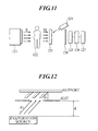
- FIG. 11 schematically shows the radiographic image conversion method using the radiographic image conversion panel of the present invention.
- the numeral 121 denotes a radiation generator
- 122 denotes a subject
- 123 denotes the radiographic image conversion panel according to the present invention
- 124 denotes a photostimulated excitation light source (of a laser or the like)
- 125 denotes a photoelectric conversion device for detecting the photostimulated fluorescence emitted by the conversion panel
- 126 denotes a device for reproducing signals detected by the photoelectric conversion device 125 as an image
- 127 denotes a device for displaying the reproduced image
- 128 denotes a filter for separating the photostimulated excitation light from the photostimulated fluorescence and transmitting only the photostimulated fluorescence.
- the devices posterior to the photoelectric conversion device 125 may be any of those which can reproduce optical information from the radiographic image conversion panel 123 as an image in any form, and by no means limited to the above.
- a radiation ray (R) from the radiation generator 121 is made incident on the radiographic image conversion panel 123 through the subject 122 (RI).
- This incident radiation ray is absorbed in the photostimulable layer of the panel 123, where its energy is accumulated and an accumulated image of the radiographic transmitted image is formed.
- this accumulated image is excited by the photostimulated excitation light from the photostimulated excitation light source 124 and emitted as photostimulated luminescence.
- this optical signal is, for example, photoelectrically converted by the photoelectric conversion device 125 such as a photomultiplier or the like, reproduced as an image by the image reproducing device 126, and is displayed by the image display device 127, so that the radiographic transmitted image of the subject can be observed.
- the photoelectric conversion device 125 such as a photomultiplier or the like
- a photostimulable phosphor layer having a photostimulable phosphor (CsBr:Eu) was formed on the surface of a support (a substrate) of glass ceramics (produced by Nippon Electric Glass Co., Ltd.) having a thickness of 1 mm and an area of 410 mm ⁇ 410 mm by using a vapor phase deposition apparatus shown in FIG. 12.
- the support was placed in the vapor phase deposition apparatus. Then, press molding was performed by using the phosphor raw material (CsBr:Eu) as the evaporation source, and the support was charged in a water-cooled crucible (not shown).
- air in the vapor phase deposition apparatus was discharged by connecting a pump to an outlet, and further, nitrogen was introduced from a gas inlet into the apparatus (flow rate: 1, 000 sccm (sccm: standard cc/min(1 ⁇ 10 -6 m 3 /min))).
- flow rate: 1, 000 sccm (sccm: standard cc/min(1 ⁇ 10 -6 m 3 /min)) After the degree of vacuum in the apparatus was kept to 6. 65 ⁇ 10 -3 Pa, the evaporation source was heated at 650°C and the distance (d) between the support and the evaporation source was made to be 60 cm.
- deposition was performed on one surface of the glass support (the substrate) by using an alkali halide phosphor comprising CsBr:0.0001Eu and by carrying the support toward the direction parallel to the longitudinal direction of the support. The deposition was terminated when the film thickness of the photostimulable phosphor layer became 400 ⁇ m. Thus, a phosphor plate was prepared.
- the phosphor plate was cut into a square of 5 cm ⁇ 5 cm.
- the polyparaxylylene film was integrally formed by deposition on the photostimulable phosphor layer and the rear surface of the support.
- the cut sample was disposed on the above-described turn table 103c, and introduced into the deposition room 103.
- Diparaxylylene vaporized by heating at 175°C in the vaporization room and radicalized by elevating the temperature under heat to 690°C in the thermal decomposition room 102 was introduced into the deposition room 103 from the inlet 103a.
- a diparaxylylene film was deposited on the whole surface of the photostimulable phosphor layer 111 and the support 112.
- the deposition was performed in twice.
- the supporting position of the support 112 by the sample supporting needle 120 was moved so as to prevent pinholes and peeling of the xylylene film.
- each of the photostimulable phosphor plates having deposited and formed thereon a polyparaxylylene film was sealed as follows.
- a laminated film containing an aluminum-deposited film VMPET composed of PET 12///VMPET70///PE15///LDPE 30 (the numerals indicated behind each resin film represent a film thickness ( ⁇ m) of each film, "///” means a dry lamination adhesive layer, "///” represents that the thickness of the adhesive layer is 3.0 ⁇ m, and the dry lamination adhesive utilized is a two-liquid reactive urethane adhesive) was used on the photostimulable phosphor layer side.
- CPP casting polypropylene
- PET polyethylene terephthalate
- /// represents an adhesive layer, the thickness of the adhesive layer in this case is 3.0 ⁇ m, and a two-liquid reactive urethane adhesive was used
- the peripheral part was fused under a reduced pressure by using an impulse sealer (sealing film: single).
- PET represents a polyethylene terephthalate
- VMPET represents an alumina-deposited polyethylene terephthalate (produced by Toyo Metallizing Co.,Ltd.)
- PE represents a polyethylene
- LDPE represents a low-density polyethylene
- CPP represents a casting polypropylene.
- the fusion was performed such that the distance between the fusion part and the phosphor plate peripheral part was 1 mm.
- An impulse sealer heater having a width of 3 mm was used at the fusion.
- radiographic image conversion panel samples in Examples 1 to 4 were prepared.
- a radiographic image conversion panel sealed with a laminated film containing the above-described deposited film was prepared as Comparative Example 1, in the same manner as in Examples except for not performing the coating with a polyparaxylylene film, on the support having formed thereon the above-described phosphor layer.
- the thus-obtained radiographic image conversion panel was evaluated according to the following method.
- the sharpness was evaluated as follows. First, an X-ray with a tube voltage of 80 kVp was irradiated to the radiographic image conversion panel through a lead-made MTF chart. Thereafter, the panel was excited with a He-Ne laser beam, the photostimulated luminescence emitted from the phosphor layer was received by the same light receiver as above and converted into an electric signal. Then, this signal was recorded in a magnetic tape after the analog/digital conversion and the magnetic tape was analyzed by a computer, whereby the modulation transfer function (MTF) of an X-ray image recorded in the magnetic tape was determined.
- MTF modulation transfer function
- each of the radiographic image conversion panels was sealed the phosphor sheet. Thereafter, each panel was scanned and excited with a He-Ne laser beam (633 nm), the photostimulated luminescence emitted from the phosphor layer was received by a light receiver (a photomultiplier with spectral sensitivity of S-5), and then its intensity was measured. The intensity obtained was defined as luminance and made to be initial sensitivity. Subsequently, each of the radiographic image conversion panels was stored in a high moisture atmosphere at a temperature of 40°C and a relative humidity of 90%, then taken out and measured on sensitivity again.
- the radiographic image conversion panel having formed thereon a polyparaxylylene film is excellent in moisture resistance as compared with the radiographic image conversion panel not provided with a polyparaxylylene film. It is also found that if the polyparaxylylene film is thicker, the moisture resistance is improved, whereas if the thickness becomes large, the sharpness is somewhat lowered. Incidentally, the panel in Comparative Example 2 is not provided with a polyparaxylylene film but doubly sealed with a film having a metal oxide-deposited layer, however, it is found that the lowering of sharpness is serious though the moisture resistance is surely improved.
- a long life-time radiographic image conversion panel where a photostimulable phosphor layer formed by a vapor phase deposition is sealed with an organic film and a deposited film can be obtained.
Landscapes
- Chemical & Material Sciences (AREA)
- Engineering & Computer Science (AREA)
- Inorganic Chemistry (AREA)
- Materials Engineering (AREA)
- Organic Chemistry (AREA)
- Physics & Mathematics (AREA)
- General Engineering & Computer Science (AREA)
- High Energy & Nuclear Physics (AREA)
- Luminescent Compositions (AREA)
- Conversion Of X-Rays Into Visible Images (AREA)
Applications Claiming Priority (4)
| Application Number | Priority Date | Filing Date | Title |
|---|---|---|---|
| JP2002375035A JP2004205354A (ja) | 2002-12-25 | 2002-12-25 | 放射線画像変換パネルの製造方法及び放射線画像変換パネル |
| JP2002375035 | 2002-12-25 | ||
| JP2003028048A JP2004239713A (ja) | 2003-02-05 | 2003-02-05 | 放射線画像変換パネル |
| JP2003028048 | 2003-02-05 |
Publications (1)
| Publication Number | Publication Date |
|---|---|
| EP1441019A1 true EP1441019A1 (fr) | 2004-07-28 |
Family
ID=32599298
Family Applications (1)
| Application Number | Title | Priority Date | Filing Date |
|---|---|---|---|
| EP03028917A Withdrawn EP1441019A1 (fr) | 2002-12-25 | 2003-12-17 | Panneau pour la conversion d'images obtenues par rayonnement |
Country Status (2)
| Country | Link |
|---|---|
| US (1) | US20050040340A1 (fr) |
| EP (1) | EP1441019A1 (fr) |
Cited By (4)
| Publication number | Priority date | Publication date | Assignee | Title |
|---|---|---|---|---|
| EP1939893A3 (fr) * | 2006-12-27 | 2008-10-08 | Konica Minolta Medical & Graphic, Inc. | Panneau de conversion d'image de rayonnement |
| CN102575160A (zh) * | 2009-09-02 | 2012-07-11 | 佳能株式会社 | 闪烁体材料 |
| US9797041B2 (en) | 2008-11-13 | 2017-10-24 | Maven Optronics Corp. | System and method for forming a thin-film phosphor layer for phosphor-converted light emitting devices |
| CN112654896A (zh) * | 2018-09-04 | 2021-04-13 | 佳能电子管器件株式会社 | 放射线检测器、放射线检测器的制造方法和装置、闪烁体面板、闪烁体面板的制造方法和装置 |
Families Citing this family (22)
| Publication number | Priority date | Publication date | Assignee | Title |
|---|---|---|---|---|
| US7029836B2 (en) * | 2003-02-10 | 2006-04-18 | Konica Minolta Holdings, Inc. | Radiographic image conversion panel and method for manufacturing the same |
| DE602004015218D1 (de) | 2003-09-17 | 2008-09-04 | Konica Minolta Med & Graphic | Strahlungsbildwandler und Verfahren zu seiner Herstellung |
| US7173247B2 (en) * | 2003-09-24 | 2007-02-06 | Radiation Monitoring Devices, Inc. | Lu1-xI3:Cex—a scintillator for gamma ray spectroscopy and time-of-flight PET |
| CN100426016C (zh) * | 2003-12-18 | 2008-10-15 | 株式会社大真空 | 滤光器 |
| JP2005181220A (ja) * | 2003-12-22 | 2005-07-07 | Fuji Photo Film Co Ltd | 放射線像変換パネル |
| EP1605472A1 (fr) * | 2004-06-10 | 2005-12-14 | Konica Minolta Medical & Graphic, Inc. | Panneau pour la conversion d'images radiographiques |
| US7435975B2 (en) * | 2005-09-30 | 2008-10-14 | Konica Minolta Medical & Graphic, Inc. | Scintillator plate for radiation and radiographic image detector |
| US20070098881A1 (en) * | 2005-10-28 | 2007-05-03 | Jean-Pierre Tahon | Method of preparing stabilized storage phosphor panels |
| JPWO2007060814A1 (ja) * | 2005-11-28 | 2009-05-07 | コニカミノルタエムジー株式会社 | 放射線用シンチレータプレート |
| WO2007062527A1 (fr) * | 2005-11-30 | 2007-06-07 | The Governors Of The University Of Alberta | Pellicules minces colonnaires organiques |
| WO2008001617A1 (fr) * | 2006-06-28 | 2008-01-03 | Konica Minolta Medical & Graphic, Inc. | Panneau scintillant |
| US20080035857A1 (en) * | 2006-08-10 | 2008-02-14 | Luc Struye | Method of manufacturing a radiation image storage panel |
| EP1890299A1 (fr) * | 2006-08-17 | 2008-02-20 | Agfa HealthCare NV | Procédé de fabrication d'un panneau de stockage d'image à rayonnement |
| EP1889893B1 (fr) * | 2006-08-17 | 2013-03-27 | Agfa HealthCare NV | Procédé de fabrication d'un écran pour l'enregistrement d'une image obtenue par rayonnement |
| TWI608760B (zh) | 2008-11-13 | 2017-12-11 | 行家光電有限公司 | 形成螢光粉轉換發光元件之方法 |
| US10214686B2 (en) | 2008-12-30 | 2019-02-26 | Nanosys, Inc. | Methods for encapsulating nanocrystals and resulting compositions |
| US8343575B2 (en) | 2008-12-30 | 2013-01-01 | Nanosys, Inc. | Methods for encapsulating nanocrystals and resulting compositions |
| US11198270B2 (en) | 2008-12-30 | 2021-12-14 | Nanosys, Inc. | Quantum dot films, lighting devices, and lighting methods |
| CN101957452A (zh) * | 2009-07-16 | 2011-01-26 | Ge医疗系统环球技术有限公司 | X射线检测器及其制造方法 |
| EP3540300B1 (fr) | 2010-11-10 | 2024-05-08 | Shoei Chemical Inc. | Films à points quantiques, dispositifs d'éclairage et procédés d'éclairage |
| US10120083B2 (en) * | 2011-06-28 | 2018-11-06 | Carestream Dental Technology Topco Limited | Radiation sensing thermoplastic composite panels |
| EP3004930B1 (fr) * | 2013-05-24 | 2019-07-10 | Teledyne Dalsa B.V. | Structure de protection contre l'humidité pour dispositif et son procédé de fabrication |
Citations (3)
| Publication number | Priority date | Publication date | Assignee | Title |
|---|---|---|---|---|
| EP0174875A2 (fr) * | 1984-09-14 | 1986-03-19 | Konica Corporation | Méthode de conversion d'une image radiographique et écran pour l'enregistrement d'énergie par rayonnement comportant une couche de matière luminescente excitable |
| EP0185534A2 (fr) * | 1984-12-17 | 1986-06-25 | Konica Corporation | Ecran pour l'enregistrement d'une image obtenue par rayonnement |
| US20030047697A1 (en) * | 2001-08-06 | 2003-03-13 | Fuji Photo Film Co., Ltd. | Preparation of radiation image storage panel |
Family Cites Families (2)
| Publication number | Priority date | Publication date | Assignee | Title |
|---|---|---|---|---|
| DE3578359D1 (de) * | 1984-12-17 | 1990-07-26 | Konishiroku Photo Ind | Schirm zum speichern eines strahlungsbildes. |
| US6847041B2 (en) * | 2001-02-09 | 2005-01-25 | Canon Kabushiki Kaisha | Scintillator panel, radiation detector and manufacture methods thereof |
-
2003
- 2003-12-17 EP EP03028917A patent/EP1441019A1/fr not_active Withdrawn
- 2003-12-19 US US10/740,932 patent/US20050040340A1/en not_active Abandoned
Patent Citations (3)
| Publication number | Priority date | Publication date | Assignee | Title |
|---|---|---|---|---|
| EP0174875A2 (fr) * | 1984-09-14 | 1986-03-19 | Konica Corporation | Méthode de conversion d'une image radiographique et écran pour l'enregistrement d'énergie par rayonnement comportant une couche de matière luminescente excitable |
| EP0185534A2 (fr) * | 1984-12-17 | 1986-06-25 | Konica Corporation | Ecran pour l'enregistrement d'une image obtenue par rayonnement |
| US20030047697A1 (en) * | 2001-08-06 | 2003-03-13 | Fuji Photo Film Co., Ltd. | Preparation of radiation image storage panel |
Cited By (4)
| Publication number | Priority date | Publication date | Assignee | Title |
|---|---|---|---|---|
| EP1939893A3 (fr) * | 2006-12-27 | 2008-10-08 | Konica Minolta Medical & Graphic, Inc. | Panneau de conversion d'image de rayonnement |
| US9797041B2 (en) | 2008-11-13 | 2017-10-24 | Maven Optronics Corp. | System and method for forming a thin-film phosphor layer for phosphor-converted light emitting devices |
| CN102575160A (zh) * | 2009-09-02 | 2012-07-11 | 佳能株式会社 | 闪烁体材料 |
| CN112654896A (zh) * | 2018-09-04 | 2021-04-13 | 佳能电子管器件株式会社 | 放射线检测器、放射线检测器的制造方法和装置、闪烁体面板、闪烁体面板的制造方法和装置 |
Also Published As
| Publication number | Publication date |
|---|---|
| US20050040340A1 (en) | 2005-02-24 |
Similar Documents
| Publication | Publication Date | Title |
|---|---|---|
| US20050040340A1 (en) | Radiographic image conversion panel | |
| JP4265139B2 (ja) | 放射線画像変換パネル及び放射線画像読み取り装置 | |
| EP1376613A2 (fr) | Panneau pour la conversion d'images obtenues par rayonnement et méthode de préparation | |
| JP2003248097A (ja) | 放射線画像変換パネル及び放射線画像変換パネルの製造方法 | |
| JP2004279086A (ja) | 放射線画像変換パネル及び放射線画像変換パネルの製造方法 | |
| US7053385B2 (en) | Radiographic image conversion panel and method for manufacturing the same | |
| EP1523014A2 (fr) | Panneau pour la conversion d'images radiographiques et méthode de préparation | |
| EP1566813A2 (fr) | Panneau pour la conversion d'images de radiation | |
| JP2004239713A (ja) | 放射線画像変換パネル | |
| US7029836B2 (en) | Radiographic image conversion panel and method for manufacturing the same | |
| EP1443526A2 (fr) | Panneau pour la conversion d'images obtenues par rayonnement | |
| JP4304998B2 (ja) | 放射線画像変換パネル及び放射線画像変換パネルの製造方法 | |
| US7202485B2 (en) | Radiation image conversion panel and preparation method thereof | |
| JP2005083792A (ja) | 放射線画像変換パネル及びその製造方法 | |
| JP4770737B2 (ja) | 放射線画像変換パネル | |
| JP4059184B2 (ja) | 放射線画像変換パネル | |
| JP2005164312A (ja) | 放射線画像変換パネル及び放射線画像変換パネルの製造方法 | |
| JP2004226251A (ja) | 放射線画像変換パネル及び放射線画像変換パネルの製造方法。 | |
| JP2006064383A (ja) | 放射線像変換パネル及びその製造方法 | |
| JP4259035B2 (ja) | 放射線画像変換パネル及び放射線画像変換パネルの製造方法 | |
| JP2006064382A (ja) | 放射線像変換パネル及び放射線像変換パネルの製造方法 | |
| JP2008116462A (ja) | 放射線画像変換パネル及び放射線画像変換パネルの製造方法 | |
| JP2006125854A (ja) | 放射線画像変換パネル及びその製造方法 | |
| JP2004301819A (ja) | 放射線画像変換パネル及び放射線画像変換パネルの製造方法 | |
| JP4461860B2 (ja) | 放射線画像変換パネル及び放射線画像変換パネルの製造方法 |
Legal Events
| Date | Code | Title | Description |
|---|---|---|---|
| PUAI | Public reference made under article 153(3) epc to a published international application that has entered the european phase |
Free format text: ORIGINAL CODE: 0009012 |
|
| AK | Designated contracting states |
Kind code of ref document: A1 Designated state(s): AT BE BG CH CY CZ DE DK EE ES FI FR GB GR HU IE IT LI LU MC NL PT RO SE SI SK TR |
|
| AX | Request for extension of the european patent |
Extension state: AL LT LV MK |
|
| 17P | Request for examination filed |
Effective date: 20040707 |
|
| AKX | Designation fees paid |
Designated state(s): DE FR GB |
|
| STAA | Information on the status of an ep patent application or granted ep patent |
Free format text: STATUS: THE APPLICATION IS DEEMED TO BE WITHDRAWN |
|
| 18D | Application deemed to be withdrawn |
Effective date: 20070702 |