EP1441067B1 - Elément de treillis profilé - Google Patents
Elément de treillis profilé Download PDFInfo
- Publication number
- EP1441067B1 EP1441067B1 EP04000601A EP04000601A EP1441067B1 EP 1441067 B1 EP1441067 B1 EP 1441067B1 EP 04000601 A EP04000601 A EP 04000601A EP 04000601 A EP04000601 A EP 04000601A EP 1441067 B1 EP1441067 B1 EP 1441067B1
- Authority
- EP
- European Patent Office
- Prior art keywords
- grid element
- elements
- wall
- profiled
- profiled grid
- Prior art date
- Legal status (The legal status is an assumption and is not a legal conclusion. Google has not performed a legal analysis and makes no representation as to the accuracy of the status listed.)
- Expired - Lifetime
Links
- 230000008878 coupling Effects 0.000 claims abstract description 26
- 238000010168 coupling process Methods 0.000 claims abstract description 26
- 238000005859 coupling reaction Methods 0.000 claims abstract description 26
- 230000000295 complement effect Effects 0.000 claims abstract description 18
- 230000002787 reinforcement Effects 0.000 claims abstract description 3
- 238000010276 construction Methods 0.000 claims abstract 2
- 239000000758 substrate Substances 0.000 claims description 5
- 208000004067 Flatfoot Diseases 0.000 claims description 3
- 229920003023 plastic Polymers 0.000 claims description 2
- 239000004033 plastic Substances 0.000 claims description 2
- 239000004698 Polyethylene Substances 0.000 claims 1
- 238000001746 injection moulding Methods 0.000 claims 1
- 239000000463 material Substances 0.000 claims 1
- 239000000203 mixture Substances 0.000 claims 1
- -1 polyethylene Polymers 0.000 claims 1
- 229920000573 polyethylene Polymers 0.000 claims 1
- 239000002131 composite material Substances 0.000 description 11
- 238000009434 installation Methods 0.000 description 10
- 210000002105 tongue Anatomy 0.000 description 9
- 230000015572 biosynthetic process Effects 0.000 description 3
- 238000005755 formation reaction Methods 0.000 description 3
- 230000006978 adaptation Effects 0.000 description 2
- 238000010409 ironing Methods 0.000 description 2
- 238000005266 casting Methods 0.000 description 1
- 230000001419 dependent effect Effects 0.000 description 1
- 238000006073 displacement reaction Methods 0.000 description 1
- 238000005516 engineering process Methods 0.000 description 1
- 238000004519 manufacturing process Methods 0.000 description 1
- 230000035939 shock Effects 0.000 description 1
- IHQKEDIOMGYHEB-UHFFFAOYSA-M sodium dimethylarsinate Chemical class [Na+].C[As](C)([O-])=O IHQKEDIOMGYHEB-UHFFFAOYSA-M 0.000 description 1
- 239000002689 soil Substances 0.000 description 1
- XLYOFNOQVPJJNP-UHFFFAOYSA-N water Substances O XLYOFNOQVPJJNP-UHFFFAOYSA-N 0.000 description 1
Images
Classifications
-
- E—FIXED CONSTRUCTIONS
- E04—BUILDING
- E04C—STRUCTURAL ELEMENTS; BUILDING MATERIALS
- E04C2/00—Building elements of relatively thin form for the construction of parts of buildings, e.g. sheet materials, slabs, or panels
- E04C2/30—Building elements of relatively thin form for the construction of parts of buildings, e.g. sheet materials, slabs, or panels characterised by the shape or structure
- E04C2/42—Gratings; Grid-like panels
- E04C2/427—Expanded metal or other monolithic gratings
-
- E—FIXED CONSTRUCTIONS
- E01—CONSTRUCTION OF ROADS, RAILWAYS, OR BRIDGES
- E01C—CONSTRUCTION OF, OR SURFACES FOR, ROADS, SPORTS GROUNDS, OR THE LIKE; MACHINES OR AUXILIARY TOOLS FOR CONSTRUCTION OR REPAIR
- E01C9/00—Special pavings; Pavings for special parts of roads or airfields
- E01C9/004—Pavings specially adapted for allowing vegetation
-
- E—FIXED CONSTRUCTIONS
- E04—BUILDING
- E04F—FINISHING WORK ON BUILDINGS, e.g. STAIRS, FLOORS
- E04F15/00—Flooring
- E04F15/02—Flooring or floor layers composed of a number of similar elements
- E04F15/10—Flooring or floor layers composed of a number of similar elements of other materials, e.g. fibrous or chipped materials, organic plastics, magnesite tiles, hardboard, or with a top layer of other materials
- E04F15/105—Flooring or floor layers composed of a number of similar elements of other materials, e.g. fibrous or chipped materials, organic plastics, magnesite tiles, hardboard, or with a top layer of other materials of organic plastics with or without reinforcements or filling materials
Definitions
- the invention relates to a profile grid element for the formation and / or reinforcement of surfaces, in particular in the heavy load area, with a footprint facing the respective laying ground and a tread surface facing away from the respective laying ground, which are connected by wall elements connected to each other, preferably lattice-like, the arrangement of Wall elements, in particular provided for backfilling, limited openings and the profile grid element on the outside each final outer walls, of which at least one outer wall is provided with at least one externally projecting coupling element for connection to a respective adjacent profile grid element to be laid.
- Such a profile grid element is for example from the DE 198 02 885 C1 known.
- such profile grid components have become known as so-called lawn grid.
- the individual lawn grid elements are in this case from a large number of similarly constructed profile grid components composed of a closed laying surface.
- the case between the individual wall elements existing openings are usually filled after the placement of the grid surface on the ground in a suitable form, preferably with a mother earth or gravel filling and optionally greened.
- the composite surface forms a framework stiffening the framework, which counteracts any formations of uneven floors, which may arise in particular by driving over a softened soil, counteracts.
- the formation of potholes or other unevenness is prevented in particular by the fact that by the stiffening of the laying surface a possible deflection of the laying ground due to a surface load is largely avoided.
- such a outside protruding coupling element can also be arranged in a region which lies between the footprint and tread surface.
- this has the consequence that the adjacent lawn grid elements must be pushed more or less lying at the same height in each other. This can lead to a cumbersome installation in case of unevenness of the laying ground.
- the displacement of the profile grid elements relative to the laying ground can also be made more difficult by the fact that it may be advantageous to first fix individual grid elements on the laying ground. In this case, the fixation of individual or all profile grid elements counteract one another slide in adjacent profile grid elements.
- the invention has for its object to provide a profile grid element, the laying of which can be performed as simple as possible on site and also allows the most flexible adaptation to the particular application.
- the profile grid element according to the invention is provided on the outside at least with a coupling element which is latched with a respective inside arranged complementary element of the respective adjacent profile grid element in at least two distinguishable defined positions, it is ensured that the profile grid element according to the invention are laid at least in two defined distinguishable arrangements can. It can be decided in each case on site, whether the adjacent profile grid elements are to be installed on impact or joint. In the case of a transfer to shock results in sections increased stiffening of the substrate and thus an overall greater resilience of the composite surface produced by the laying of the profile grid elements. In the alternative laying on joint results in the same number of profile grid elements an increased installation area.
- a spring tongue is provided with at least one latching pin projecting on the upper side, which can be latched to the corresponding complementary piece of the respective adjacent lawn grid element.
- the complementary piece to the spring tongue element described is one of the respective adjacent outer wall arranged holding web, wherein the locking bolt can engage either in the area between outer wall and retaining web, or the spring tongue can be pushed so far that the spring tongue not only the outer wall, but also the completely engages under the holding wall connected to the outer wall and locked with this.
- the first installation of the locking bolt is fixed in its arranged between the holding web and the outer wall position on both sides such that a relative movement of the one profile grid element is excluded for each adjacent profile grid element.
- both the outer walls and the locking pin are moved to stop, so that in this respect also a relative movement the adjacent profile grid elements is effectively avoided.
- the corresponding complementary element for this coupling element is arranged in the region of the outer wall underside protruding pegs, which pierce under normal installation the bracket element in the direction of the laying ground and thus to a further locking of the adjacent profile grid elements and also to a fixation of the composite surface formed by the profile grid elements on the Make laying ground.
- the profile grid elements are inserted from top to bottom to form a composite surface in one another. The profile grid elements once inserted into each other are fixed in a single operation both with each other and with respect to the laying ground.
- the profile grid element preferably has a quadrangular shape, wherein in each case the, preferably at right angles, adjacent outer walls are provided with the respective outer side projecting coupling elements and each with the other outer walls with the corresponding complementary elements. Due to this arrangement of Coupling and complementary elements is ensured at least in rectangular profile grid elements that the profile grid elements can be connected to each other either in the range of broadsides as well as the long sides.
- the wall elements of the profile grid elements intersect in the region of so-called orthogonally extending crossing webs, which are underlaid by flat foot elements.
- the flat foot elements provide a defined footprint of the respective profile grid elements and thereby facilitate, for example, the laying in a particularly soggy or otherwise spongy ground. Overall, the foot elements increase the footprint of the respective profile grid elements.
- the foot elements are each provided with an edge flange, so that collects any leachate within these foot elements and thus can serve as a water reservoir in the case of a greening of the composite surface.
- the wall elements jump back in the area of the crossing bridges. This causes a profiling of the composite surface formed with the profile grid elements. Such a profiling is desirable for reasons of stability and driving safety and, moreover, facilitates any casting technology production of the profile grid elements according to the invention.
- profile grid elements described above are made of recycled plastic.
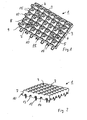
- FIG. 1 consists of the profile grid element 1 substantially of wall elements 2, which are interleaved with each other like a grid to form openings 3.
- the wall elements 2 intersect to form, when properly mounted, vertically extending Crossing webs 4.
- the upper edges of the wall elements 2 jump back slightly in the area of the crossing webs, so that the upper-side running surface is profiled.
- the so-called footprint of the profile grid element 1 is located opposite the tread surface and thus facing the respective laying ground when mounted as intended.
- the crossing webs 4 are underlaid by foot elements 5 which rise flat on the laying surface.
- the crossing webs 4 open substantially centrally into the corresponding foot elements 5, which are enclosed by an edge flange 6 projecting on the upper side all around in the direction of the tread surface.
- the profile grid element 1 has a rectangular shape, wherein the profile grid element 1 is surrounded by outer wall elements 7 around. How out FIG. 1 can be seen, two adjoining outer walls 7 are provided in the area of the footprint with on this outer walls outside projecting coupling elements.
- the coupling elements a distinction can be made between U-shaped protruding stirrup elements 10 and spring tongues 11, which are arranged equidistant from one another along the outer wall, alternatingly.
- each of the coupling elements (10 and 11) is substantially associated with an opening 3 of the profile grid element 1.
- the coupling elements are used for connection to a respectively adjoining, adjacent profile grid element for forming a composite surface formed by the profile grid elements 1, as they are used to solidify a surface.
- the coupling elements 10 and 11 are engaged with corresponding complementary elements.
- the profile grid elements also have in the area of the footprint insert elements 8 with triangular openings 9, through which the profile grid elements can be anchored by means of additional Erdnägel additionally in the laying ground.
- the additional pegs, which are pushed through the triangular openings 9, have a corresponding triangular contour.
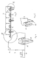
- the ironing elements 10 are doing with those FIG. 2 apparent Erdnägeln 12 brought in such a way that the respective adjacent profile grid element 1 is laid from top to bottom, that the pegs 12 are anchored by the bracket elements 10 through with the respective laying ground.
- the spring tongues 11 additionally engage with their respective complementary element.
- This is a holding web 14 which is assigned to a recess 13 of the respective outer wall 7 and is connected on the inside to the respective outer wall 7.
- the spring tongues 11 in the direction of the tread protruding locking pin 15 which can be locked in two defined positions with the respective retaining web 14.
- laying the respectively adjacent profile grid element 1 a distinction can be made between two defined types of laying. Either the locking bolts can be inserted in a position between the retaining web 14 and the respective outer wall 7. Then adjacent profile grid elements are laid on joint.
- the respectively adjacent profiled grille element 1 can also be set so that the spring tongue 11 engages completely below the retaining web 14 arranged on the inside of the adjoining outer wall 7 and the locking bolts engage behind the retaining web 14 in a position which causes the profiled grille elements 1 to be placed in abutment.
- the retaining clips 14 are arranged at such a distance from the respective outer wall 7, that this distance substantially corresponds to the cross section of the locking pin 15.
- the Erdnägel 12 and the recesses 14 are arranged with the holding webs 13 arranged on the inside. Also in the area of the pegs 12, the respective outer wall 7 has a recess 16, through which the stirrup element 10 can be positively inserted into the outer wall 7.
- the pegs 12 are, as in particular from FIG. 5 can be seen, connected via a bridge web 17 with the respective outer wall 7.
- the pegs 12 have a wedge shape, which is suitable for permanent fixation in the laying ground.
- a profile grid element 1 which can be used in particular for stiffening a laying ground.
- a second profile grid element 1 either on impact or joint connected.
- the pegs 12 of the respective adjacent lattice element 1 are pushed by the corresponding bracket elements 10 and the latching bolt 15 is locked either in the area between the holding web 14 and the outer wall 7 or inside behind the retaining web 14 and accordingly the adjacent profile grid elements 1 either on joint or on Push relocated.
- the pegs are an integral part of the profile grid elements, the adjacent profile grid element is fixed immediately to the laying ground.
- the grid structure can be filled by filling the openings 3 with topsoil or pebbles or a substrate corresponding to the ground floor and optionally planted.
- the used for backfill upper layer of the laying ground is thus stiffened by the lattice-like structure of the profile grid elements and thus can withstand increased loads such as driving on vehicles.
- easier assembly profile grid element according to the invention has the advantage of an optional installation on joint or on impact.
Landscapes
- Engineering & Computer Science (AREA)
- Architecture (AREA)
- Civil Engineering (AREA)
- Structural Engineering (AREA)
- Road Paving Structures (AREA)
- Tires In General (AREA)
- Bridges Or Land Bridges (AREA)
- Golf Clubs (AREA)
- Prostheses (AREA)
- Control Of Motors That Do Not Use Commutators (AREA)
Claims (12)
- Elément de treillis profilé pour réaliser et/ou renforcer des surfaces, en particulier dans le domaine des charges lourdes, avec une face de pose tournée vers la base d'installation respective et une face d'usure détournée de la base d'installation respective, qui sont reliées par des éléments de paroi (2) reliés ensemble, de préférence à la manière d'un treillis, dans lequel l'agencement des éléments de paroi (2) délimite des ouvertures (3) prévues en particulier pour un remplissage et l'élément de treillis profilé (1) est terminé à l'extérieur par des parois extérieures périphériques (7), dont au moins une paroi extérieure (7) est munie d'au moins un élément de couplage (10 ou 11) dépassant vers l'extérieur en vue d'un raccordement avec un autre élément de treillis profilé (1) à poser respectivement à côté,
caractérisé en ce que
l'élément de couplage peut s'enclencher dans au moins une pièce complémentaire (13) reliée sur le côté intérieur à la paroi extérieure (7) respectivement adjacente de l'élément de treillis profilé (1) respectivement voisin, dans au moins deux positions définies distinctes. - Elément de treillis profilé selon la revendication 1, caractérisé en ce qu'au moins l'un des éléments de couplage, disposés de préférence dans la zone de la face de pose, est une languette élastique (11) avec au moins un boulon d'arrêt (15) dépassant au niveau du côté supérieur en direction de la face d'usure et qui peut s'enclencher dans une pièce complémentaire correspondante de l'élément de treillis profilé (1) respectivement à disposer à côté.
- Elément de treillis profilé selon la revendication 2, caractérisé en ce qu'au moins une paroi extérieure (7) de l'élément de treillis profilé (1) est munie d'au moins une pièce complémentaire disposée du côté intérieur de telle sorte que cette paroi extérieure (7) est respectivement munie à la hauteur de l'élément de couplage correspondant de l'élément de treillis profilé (1) respectivement à poser à côté respectivement d'un évidement pour recevoir la languette élastique (11), dans lequel cet évidement (14) se voit associer du côté intérieur une entretoise de maintien (13), disposée de façon espacée d'une mesure correspondant au moins approximativement à la section transversale du boulon d'arrêt (15) de la languette élastique (11), en vue d'un enclenchement avec la languette élastique (11).
- Elément de treillis profilé selon la revendication 3, caractérisé en ce qu'en cas de montage correct, le boulon d'arrêt (15) peut s'enclencher entre l'entretoise de maintien (13) et la paroi extérieure respective (7) ou dans une position passant complètement sous l'entretoise de maintien (13).
- Elément de treillis profilé selon l'une quelconque des revendications précédentes, caractérisé en ce qu'au moins une paroi extérieure (7) est munie du côté extérieur d'au moins un élément en boucle (10), disposé de préférence dans la zone de la face de pose, en tant qu'élément de couplage supplémentaire.
- Elément de treillis profilé selon la revendication 5, caractérisé en ce qu'au moins une paroi extérieure (7) est munie d'un évidement (16) pour recevoir l'élément en boucle (10), dans lequel, dans la zone de cet évidement (16), des piquets (12) dépassant respectivement de la surface de pose sur le côté inférieur sont articulés en tant que pièces complémentaires supplémentaires sur l'élément de treillis profilé (1) de telle sorte qu'ils traversent en cas de montage correct les éléments en boucle (10) insérés à travers l'évidement de l'élément de treillis profilé (1) respectivement adjacent en direction de la base d'installation.
- Elément de treillis profilé selon la revendication 5 ou 6, caractérisé en ce qu'au moins sur une paroi extérieure (7) de l'élément de treillis profilé (1), dans la zone de la face de pose, respectivement de façon espacée les uns des autres en alternance, un élément en boucle (10) et une languette élastique (11) sont disposés comme des éléments de couplage, et en ce que sur le côté respectivement opposé du même élément de treillis profilé (1), les pièces complémentaires correspondantes sont également disposées en alternance.
- Elément de treillis profilé selon l'une quelconque des revendications précédentes, caractérisé en ce que l'élément de treillis profilé (1) présente une section transversale substantiellement rectangulaire avec quatre parois extérieures (7), dans lequel des parois extérieures respectivement adjacentes sont munies des éléments de couplage (10, 11) dépassant vers l'extérieur, et les deux autres parois extérieures sont munies des éléments complémentaires (12, 13) correspondants dépassant vers l'intérieur.
- Elément de treillis profilé selon l'une quelconque des revendications précédentes, caractérisé en ce que les éléments de paroi (7) imbriqués les uns dans les autres se rencontrent respectivement au niveau d'entretoises d'intersection (4) s'étendant de façon au moins approximativement orthogonale, dans lequel des éléments de pied plans (5) passant sous ces entretoises d'intersection dans la zone de la face de pose.
- Elément de treillis profilé selon la revendication 9, caractérisé en ce que les éléments de treillis de pied (5) sont bordés respectivement par une collerette périphérique (6) dépassant au niveau du côté supérieur en direction de la face d'usure.
- Elément de treillis profilé selon la revendication 9 ou 10, caractérisé en ce que l'arête supérieure formant substantiellement la face d'usure des éléments de paroi (2) se trouve en retrait dans la zone de raccordement avec les entretoises d'intersection (4).
- Elément de treillis profilé selon l'une quelconque des revendications précédentes, caractérisé en ce que l'élément de treillis profilé (1) est fabriqué d'un seul tenant à partir d'un mélange de polyéthylène, de préférence d'une matière plastique de recyclage, en particulier selon un procédé de moulage par injection.
Applications Claiming Priority (2)
| Application Number | Priority Date | Filing Date | Title |
|---|---|---|---|
| DE20300474U DE20300474U1 (de) | 2003-01-14 | 2003-01-14 | Profilgitterelement |
| DE20300474U | 2003-01-14 |
Publications (3)
| Publication Number | Publication Date |
|---|---|
| EP1441067A2 EP1441067A2 (fr) | 2004-07-28 |
| EP1441067A3 EP1441067A3 (fr) | 2005-04-13 |
| EP1441067B1 true EP1441067B1 (fr) | 2008-08-13 |
Family
ID=7979054
Family Applications (1)
| Application Number | Title | Priority Date | Filing Date |
|---|---|---|---|
| EP04000601A Expired - Lifetime EP1441067B1 (fr) | 2003-01-14 | 2004-01-14 | Elément de treillis profilé |
Country Status (3)
| Country | Link |
|---|---|
| EP (1) | EP1441067B1 (fr) |
| AT (1) | ATE404733T1 (fr) |
| DE (2) | DE20300474U1 (fr) |
Families Citing this family (3)
| Publication number | Priority date | Publication date | Assignee | Title |
|---|---|---|---|---|
| US8651770B2 (en) | 2009-08-18 | 2014-02-18 | Tensar Corporation, Llc | Erosion control ballast and soil confinement mat |
| RU2473729C1 (ru) * | 2011-08-08 | 2013-01-27 | Олег Романович Дутко | Панель газонной решетки |
| RU2715133C1 (ru) * | 2019-10-07 | 2020-02-25 | Владимир Степанович Григорьев | Способ парковки транспортных средств на дворовой территории и устройство для его осуществления |
Family Cites Families (3)
| Publication number | Priority date | Publication date | Assignee | Title |
|---|---|---|---|---|
| GB2321077B (en) * | 1997-01-10 | 1999-01-27 | Cooper Clarke Group Plc | A grass protection system |
| DE19802885C1 (de) | 1998-01-27 | 1999-05-06 | Weber Alfred | Profilgitterbauteil |
| DE10062711C2 (de) * | 1999-12-15 | 2003-07-03 | Ritter Gmbh | Kunststoffgitterplatte zur Befestigung von Straßenbanketten |
-
2003
- 2003-01-14 DE DE20300474U patent/DE20300474U1/de not_active Expired - Lifetime
-
2004
- 2004-01-14 DE DE502004007809T patent/DE502004007809D1/de not_active Expired - Lifetime
- 2004-01-14 EP EP04000601A patent/EP1441067B1/fr not_active Expired - Lifetime
- 2004-01-14 AT AT04000601T patent/ATE404733T1/de not_active IP Right Cessation
Also Published As
| Publication number | Publication date |
|---|---|
| DE20300474U1 (de) | 2003-04-17 |
| EP1441067A2 (fr) | 2004-07-28 |
| EP1441067A3 (fr) | 2005-04-13 |
| DE502004007809D1 (de) | 2008-09-25 |
| ATE404733T1 (de) | 2008-08-15 |
Similar Documents
| Publication | Publication Date | Title |
|---|---|---|
| EP0224095B1 (fr) | Panneau de treillis en matière synthétique, en particulier en matière synthétique de recyclage | |
| DE69822035T2 (de) | Stapelstruktur | |
| DE9208359U1 (de) | Aus Kunststoff bestehendes Mehrzweckbauteil | |
| EP0400158B1 (fr) | Dispositif de renforcement de gazonnement | |
| EP0455260A1 (fr) | Elément de support pour surfaces de gazon | |
| EP2452018A2 (fr) | Plaque d'appui présentant des parties de plaque et des cavités réceptrices carrées disposées en rangs et en colonnes de manière décalée les unes par rapport aux autres | |
| EP1747331A1 (fr) | Mur de soutenement et agglomere de beton pour la fabrication d'un mur de soutenement | |
| EP1441067B1 (fr) | Elément de treillis profilé | |
| DE10062711C2 (de) | Kunststoffgitterplatte zur Befestigung von Straßenbanketten | |
| DE20121313U1 (de) | Bodenbelagplatte | |
| EP3375935B1 (fr) | Pavé en pierre doublé | |
| DE3837124A1 (de) | Doppelseitig verlegbare gitterplatte aus kunststoff, insbesondere aus recycling - kunststoff | |
| EP4392615B1 (fr) | Structure souterraine pour le guidage d'une conduite | |
| AT506754B1 (de) | Bepflanzbarer gitterkörper zum aufnehmen von verkehrslasten | |
| DE19707355C2 (de) | Fertigteilsatz zur Erstellung von Fundamenten für Baumroste | |
| DE19640819A1 (de) | Verlegeelementanordnung für befestigte Rasenflächen | |
| DE2937478A1 (de) | Bauteilsatz und bauelement zur herstellung von bauwerken sowie damit gebildete mauer und verwendung zur mauerherstellung | |
| DE19704425C2 (de) | Kunststeinelement | |
| EP0101022B1 (fr) | Mur en éléments profilés, préfabriqués et destinés à être assemblés, en particulier pour la protection contre les bruits et pour le camouflage | |
| EP1408161B1 (fr) | Bloc de construction en béton pour un mur de soutènement avec une géogrille de rétention | |
| DE202016105844U1 (de) | Böschungssicherungseinrichtung sowie damit hergestelltes Böschungsbauwerk | |
| EP0679764B1 (fr) | Panneau de treillis pour surfaces de gazon et consolidation des surfaces de gazon avec de tels panneaux | |
| DE102017000128A1 (de) | Gabionenwandmodul und Verfahren zur Herstellung einer Gabionenwand mit wenigstens einem Gabionenwandmodul | |
| DE29823733U1 (de) | Gitterkonstruktion zum Hinterfüllen mit Schüttmaterial | |
| EP2521815B1 (fr) | Élément antibruit végétal et paroi antibruit |
Legal Events
| Date | Code | Title | Description |
|---|---|---|---|
| PUAI | Public reference made under article 153(3) epc to a published international application that has entered the european phase |
Free format text: ORIGINAL CODE: 0009012 |
|
| AK | Designated contracting states |
Kind code of ref document: A2 Designated state(s): AT BE BG CH CY CZ DE DK EE ES FI FR GB GR HU IE IT LI LU MC NL PT RO SE SI SK TR |
|
| AX | Request for extension of the european patent |
Extension state: AL LT LV MK |
|
| PUAL | Search report despatched |
Free format text: ORIGINAL CODE: 0009013 |
|
| AK | Designated contracting states |
Kind code of ref document: A3 Designated state(s): AT BE BG CH CY CZ DE DK EE ES FI FR GB GR HU IE IT LI LU MC NL PT RO SE SI SK TR |
|
| AX | Request for extension of the european patent |
Extension state: AL LT LV MK |
|
| RIC1 | Information provided on ipc code assigned before grant |
Ipc: 7E 04F 15/02 B Ipc: 7E 01C 9/00 A Ipc: 7E 04C 2/42 B Ipc: 7E 04F 15/10 B |
|
| 17P | Request for examination filed |
Effective date: 20050524 |
|
| AKX | Designation fees paid |
Designated state(s): AT BE BG CH CY CZ DE DK EE ES FI FR GB GR HU IE IT LI LU MC NL PT RO SE SI SK TR |
|
| RAP1 | Party data changed (applicant data changed or rights of an application transferred) |
Owner name: HAURATON GMBH & CO. KG |
|
| GRAP | Despatch of communication of intention to grant a patent |
Free format text: ORIGINAL CODE: EPIDOSNIGR1 |
|
| GRAS | Grant fee paid |
Free format text: ORIGINAL CODE: EPIDOSNIGR3 |
|
| GRAA | (expected) grant |
Free format text: ORIGINAL CODE: 0009210 |
|
| AK | Designated contracting states |
Kind code of ref document: B1 Designated state(s): AT BE BG CH CY CZ DE DK EE ES FI FR GB GR HU IE IT LI LU MC NL PT RO SE SI SK TR |
|
| REG | Reference to a national code |
Ref country code: GB Ref legal event code: FG4D Free format text: NOT ENGLISH |
|
| REG | Reference to a national code |
Ref country code: CH Ref legal event code: EP |
|
| REG | Reference to a national code |
Ref country code: IE Ref legal event code: FG4D Free format text: LANGUAGE OF EP DOCUMENT: GERMAN |
|
| REF | Corresponds to: |
Ref document number: 502004007809 Country of ref document: DE Date of ref document: 20080925 Kind code of ref document: P |
|
| PG25 | Lapsed in a contracting state [announced via postgrant information from national office to epo] |
Ref country code: NL Free format text: LAPSE BECAUSE OF FAILURE TO SUBMIT A TRANSLATION OF THE DESCRIPTION OR TO PAY THE FEE WITHIN THE PRESCRIBED TIME-LIMIT Effective date: 20080813 Ref country code: ES Free format text: LAPSE BECAUSE OF FAILURE TO SUBMIT A TRANSLATION OF THE DESCRIPTION OR TO PAY THE FEE WITHIN THE PRESCRIBED TIME-LIMIT Effective date: 20081124 |
|
| PG25 | Lapsed in a contracting state [announced via postgrant information from national office to epo] |
Ref country code: FI Free format text: LAPSE BECAUSE OF FAILURE TO SUBMIT A TRANSLATION OF THE DESCRIPTION OR TO PAY THE FEE WITHIN THE PRESCRIBED TIME-LIMIT Effective date: 20080813 Ref country code: SI Free format text: LAPSE BECAUSE OF FAILURE TO SUBMIT A TRANSLATION OF THE DESCRIPTION OR TO PAY THE FEE WITHIN THE PRESCRIBED TIME-LIMIT Effective date: 20080813 |
|
| REG | Reference to a national code |
Ref country code: IE Ref legal event code: FD4D |
|
| PG25 | Lapsed in a contracting state [announced via postgrant information from national office to epo] |
Ref country code: IE Free format text: LAPSE BECAUSE OF FAILURE TO SUBMIT A TRANSLATION OF THE DESCRIPTION OR TO PAY THE FEE WITHIN THE PRESCRIBED TIME-LIMIT Effective date: 20080813 Ref country code: DK Free format text: LAPSE BECAUSE OF FAILURE TO SUBMIT A TRANSLATION OF THE DESCRIPTION OR TO PAY THE FEE WITHIN THE PRESCRIBED TIME-LIMIT Effective date: 20080813 Ref country code: BG Free format text: LAPSE BECAUSE OF FAILURE TO SUBMIT A TRANSLATION OF THE DESCRIPTION OR TO PAY THE FEE WITHIN THE PRESCRIBED TIME-LIMIT Effective date: 20081113 |
|
| PGFP | Annual fee paid to national office [announced via postgrant information from national office to epo] |
Ref country code: AT Payment date: 20090119 Year of fee payment: 6 |
|
| PG25 | Lapsed in a contracting state [announced via postgrant information from national office to epo] |
Ref country code: CZ Free format text: LAPSE BECAUSE OF FAILURE TO SUBMIT A TRANSLATION OF THE DESCRIPTION OR TO PAY THE FEE WITHIN THE PRESCRIBED TIME-LIMIT Effective date: 20080813 Ref country code: SK Free format text: LAPSE BECAUSE OF FAILURE TO SUBMIT A TRANSLATION OF THE DESCRIPTION OR TO PAY THE FEE WITHIN THE PRESCRIBED TIME-LIMIT Effective date: 20080813 Ref country code: RO Free format text: LAPSE BECAUSE OF FAILURE TO SUBMIT A TRANSLATION OF THE DESCRIPTION OR TO PAY THE FEE WITHIN THE PRESCRIBED TIME-LIMIT Effective date: 20080813 Ref country code: PT Free format text: LAPSE BECAUSE OF FAILURE TO SUBMIT A TRANSLATION OF THE DESCRIPTION OR TO PAY THE FEE WITHIN THE PRESCRIBED TIME-LIMIT Effective date: 20090113 |
|
| PLBE | No opposition filed within time limit |
Free format text: ORIGINAL CODE: 0009261 |
|
| STAA | Information on the status of an ep patent application or granted ep patent |
Free format text: STATUS: NO OPPOSITION FILED WITHIN TIME LIMIT |
|
| 26N | No opposition filed |
Effective date: 20090514 |
|
| PG25 | Lapsed in a contracting state [announced via postgrant information from national office to epo] |
Ref country code: EE Free format text: LAPSE BECAUSE OF FAILURE TO SUBMIT A TRANSLATION OF THE DESCRIPTION OR TO PAY THE FEE WITHIN THE PRESCRIBED TIME-LIMIT Effective date: 20080813 |
|
| PG25 | Lapsed in a contracting state [announced via postgrant information from national office to epo] |
Ref country code: MC Free format text: LAPSE BECAUSE OF NON-PAYMENT OF DUE FEES Effective date: 20090131 Ref country code: IT Free format text: LAPSE BECAUSE OF FAILURE TO SUBMIT A TRANSLATION OF THE DESCRIPTION OR TO PAY THE FEE WITHIN THE PRESCRIBED TIME-LIMIT Effective date: 20080813 |
|
| REG | Reference to a national code |
Ref country code: CH Ref legal event code: PL |
|
| GBPC | Gb: european patent ceased through non-payment of renewal fee |
Effective date: 20090114 |
|
| PG25 | Lapsed in a contracting state [announced via postgrant information from national office to epo] |
Ref country code: LI Free format text: LAPSE BECAUSE OF NON-PAYMENT OF DUE FEES Effective date: 20090131 Ref country code: CH Free format text: LAPSE BECAUSE OF NON-PAYMENT OF DUE FEES Effective date: 20090131 |
|
| PG25 | Lapsed in a contracting state [announced via postgrant information from national office to epo] |
Ref country code: GB Free format text: LAPSE BECAUSE OF NON-PAYMENT OF DUE FEES Effective date: 20090114 |
|
| PG25 | Lapsed in a contracting state [announced via postgrant information from national office to epo] |
Ref country code: SE Free format text: LAPSE BECAUSE OF FAILURE TO SUBMIT A TRANSLATION OF THE DESCRIPTION OR TO PAY THE FEE WITHIN THE PRESCRIBED TIME-LIMIT Effective date: 20081113 |
|
| PG25 | Lapsed in a contracting state [announced via postgrant information from national office to epo] |
Ref country code: BE Free format text: LAPSE BECAUSE OF NON-PAYMENT OF DUE FEES Effective date: 20090131 |
|
| PG25 | Lapsed in a contracting state [announced via postgrant information from national office to epo] |
Ref country code: GR Free format text: LAPSE BECAUSE OF FAILURE TO SUBMIT A TRANSLATION OF THE DESCRIPTION OR TO PAY THE FEE WITHIN THE PRESCRIBED TIME-LIMIT Effective date: 20081114 |
|
| PG25 | Lapsed in a contracting state [announced via postgrant information from national office to epo] |
Ref country code: AT Free format text: LAPSE BECAUSE OF NON-PAYMENT OF DUE FEES Effective date: 20100114 |
|
| PG25 | Lapsed in a contracting state [announced via postgrant information from national office to epo] |
Ref country code: LU Free format text: LAPSE BECAUSE OF NON-PAYMENT OF DUE FEES Effective date: 20090114 |
|
| PG25 | Lapsed in a contracting state [announced via postgrant information from national office to epo] |
Ref country code: HU Free format text: LAPSE BECAUSE OF FAILURE TO SUBMIT A TRANSLATION OF THE DESCRIPTION OR TO PAY THE FEE WITHIN THE PRESCRIBED TIME-LIMIT Effective date: 20090214 |
|
| PG25 | Lapsed in a contracting state [announced via postgrant information from national office to epo] |
Ref country code: TR Free format text: LAPSE BECAUSE OF FAILURE TO SUBMIT A TRANSLATION OF THE DESCRIPTION OR TO PAY THE FEE WITHIN THE PRESCRIBED TIME-LIMIT Effective date: 20080813 |
|
| PG25 | Lapsed in a contracting state [announced via postgrant information from national office to epo] |
Ref country code: CY Free format text: LAPSE BECAUSE OF FAILURE TO SUBMIT A TRANSLATION OF THE DESCRIPTION OR TO PAY THE FEE WITHIN THE PRESCRIBED TIME-LIMIT Effective date: 20080813 |
|
| PGFP | Annual fee paid to national office [announced via postgrant information from national office to epo] |
Ref country code: FR Payment date: 20140124 Year of fee payment: 11 |
|
| REG | Reference to a national code |
Ref country code: DE Ref legal event code: R082 Ref document number: 502004007809 Country of ref document: DE |
|
| REG | Reference to a national code |
Ref country code: DE Ref legal event code: R081 Ref document number: 502004007809 Country of ref document: DE Owner name: NAUJOKS, VOLKER, DE Free format text: FORMER OWNER: HAURATON GMBH & CO. KG, 76437 RASTATT, DE Effective date: 20150216 |
|
| PGFP | Annual fee paid to national office [announced via postgrant information from national office to epo] |
Ref country code: DE Payment date: 20150202 Year of fee payment: 12 |
|
| REG | Reference to a national code |
Ref country code: FR Ref legal event code: ST Effective date: 20150930 |
|
| PG25 | Lapsed in a contracting state [announced via postgrant information from national office to epo] |
Ref country code: FR Free format text: LAPSE BECAUSE OF NON-PAYMENT OF DUE FEES Effective date: 20150202 |
|
| REG | Reference to a national code |
Ref country code: DE Ref legal event code: R119 Ref document number: 502004007809 Country of ref document: DE |
|
| PG25 | Lapsed in a contracting state [announced via postgrant information from national office to epo] |
Ref country code: DE Free format text: LAPSE BECAUSE OF NON-PAYMENT OF DUE FEES Effective date: 20160802 |