EP1441073A2 - Betonschutzwand - Google Patents
Betonschutzwand Download PDFInfo
- Publication number
- EP1441073A2 EP1441073A2 EP04450012A EP04450012A EP1441073A2 EP 1441073 A2 EP1441073 A2 EP 1441073A2 EP 04450012 A EP04450012 A EP 04450012A EP 04450012 A EP04450012 A EP 04450012A EP 1441073 A2 EP1441073 A2 EP 1441073A2
- Authority
- EP
- European Patent Office
- Prior art keywords
- concrete
- protective wall
- wall according
- concrete protective
- profile
- Prior art date
- Legal status (The legal status is an assumption and is not a legal conclusion. Google has not performed a legal analysis and makes no representation as to the accuracy of the status listed.)
- Granted
Links
- 230000001681 protective effect Effects 0.000 title claims abstract description 38
- 230000015572 biosynthetic process Effects 0.000 claims description 4
- 238000006073 displacement reaction Methods 0.000 claims description 4
- 238000007373 indentation Methods 0.000 claims 1
- 230000000149 penetrating effect Effects 0.000 claims 1
- 238000005553 drilling Methods 0.000 abstract 2
- 239000000463 material Substances 0.000 description 7
- 239000000758 substrate Substances 0.000 description 4
- 230000000694 effects Effects 0.000 description 3
- 238000009434 installation Methods 0.000 description 2
- 238000004873 anchoring Methods 0.000 description 1
- 230000014759 maintenance of location Effects 0.000 description 1
- 238000000034 method Methods 0.000 description 1
- 239000002689 soil Substances 0.000 description 1
Images

Classifications
-
- E—FIXED CONSTRUCTIONS
- E01—CONSTRUCTION OF ROADS, RAILWAYS, OR BRIDGES
- E01F—ADDITIONAL WORK, SUCH AS EQUIPPING ROADS OR THE CONSTRUCTION OF PLATFORMS, HELICOPTER LANDING STAGES, SIGNS, SNOW FENCES, OR THE LIKE
- E01F15/00—Safety arrangements for slowing, redirecting or stopping errant vehicles, e.g. guard posts or bollards; Arrangements for reducing damage to roadside structures due to vehicular impact
- E01F15/02—Continuous barriers extending along roads or between traffic lanes
- E01F15/04—Continuous barriers extending along roads or between traffic lanes essentially made of longitudinal beams or rigid strips supported above ground at spaced points
- E01F15/0476—Foundations
-
- E—FIXED CONSTRUCTIONS
- E01—CONSTRUCTION OF ROADS, RAILWAYS, OR BRIDGES
- E01F—ADDITIONAL WORK, SUCH AS EQUIPPING ROADS OR THE CONSTRUCTION OF PLATFORMS, HELICOPTER LANDING STAGES, SIGNS, SNOW FENCES, OR THE LIKE
- E01F15/00—Safety arrangements for slowing, redirecting or stopping errant vehicles, e.g. guard posts or bollards; Arrangements for reducing damage to roadside structures due to vehicular impact
- E01F15/02—Continuous barriers extending along roads or between traffic lanes
- E01F15/08—Continuous barriers extending along roads or between traffic lanes essentially made of walls or wall-like elements ; Cable-linked blocks
- E01F15/081—Continuous barriers extending along roads or between traffic lanes essentially made of walls or wall-like elements ; Cable-linked blocks characterised by the use of a specific material
- E01F15/083—Continuous barriers extending along roads or between traffic lanes essentially made of walls or wall-like elements ; Cable-linked blocks characterised by the use of a specific material using concrete
Definitions
- the invention relates to a concrete protective wall according to the preamble of claim 1.
- Such a concrete protective wall was e.g. known from AT 388 006 B.
- Known solution holes are arranged in the foot parts, penetrated by screws are and are aligned substantially perpendicular to the contact surface.
- AT 393 146 B has made known a guide device that consists of the front lined up concrete base is formed. These bases point in opposite directions trained and interlocking stimuli and are with from the top to Footprint provided in the assembled state vertical through openings are essentially double T-shaped in cross section and for receiving Serve piles with a 1 profile. These piles penetrate these breakthroughs and are in rammed the ground.
- the aim of the invention is to avoid these disadvantages and a concrete protective wall Propose the type mentioned above, which is simple in structure and simple Installation distinguishes and also reliably reduce larger impact energies and therefore also can withstand heavier vehicles even with only small deformation spaces.
- a concrete protective wall according to the invention is particularly suitable for securing funds from offset lanes, but also to protect against obstacles that a would not withstand vehicle impact, such as Lighting masts, gantries, Drainage shafts and the like, but also to prevent falls on embankments. There is one high level of security even if only due to the local conditions small deformation spaces can be provided.
- the proposed features ensure that the mentioned wedges of the Substrate material earlier in the event of an impact with a correspondingly high energy build up compared to the one rammed parallel to the normal plane onto the footprint Profiles. This means that the impact energy can be reduced in a shorter way.
- a particularly suitable deflection of the horizontal forces can be achieved through the features of Claim 2 can be achieved, wherein the concrete element in the event of an impact Profile bars is pulled into the ground.
- a concrete protective wall according to the invention can have the features of claim 3 can be adapted to the respective requirements and circumstances in a very simple manner.
- a Concrete protective wall can be achieved, which has a good protective effect with sufficient Resilience, which means that the concrete bulkhead also absorbs a lot of energy small shifts can be ensured.
- the features of claim 5 result in the advantage that the concrete protective wall a relatively low energy impact, such as in the event of a car crash Case will be, essentially, like a loosely placed on the ground
- the concrete protective wall reacts and the impact energy is reduced essentially by itself There is friction between the contact surface of the concrete wall and the ground. Only at; only when Due to their higher impact energy, the profiles act when these energies are broken down Deformation and the associated deformation work and the formation of wedges of the base material when moving the profiles with.
- the two kick last-mentioned effects essentially only in the event of an impact of a truck and also they are stopped in a short way and e.g. secured against a crash can.
- a particularly high pull-out force for a profile bar can be achieved through the features of the Reach claim 13.
- the invention further relates to a concrete element for the formation of an inventive Concrete protective wall.
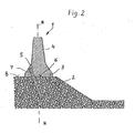
- a concrete protective wall according to the invention is, as shown in FIG can be seen, assembled from a variety of concrete elements 1, which on the Stand underground 2 and are connected to each other in the usual way at the end.
- the concrete elements 1 have a essential T-shaped cross-section, one leg forming a foot part 3, whose outer surface facing away from the second wall part 4 forms a contact surface 6.
- This foot part 3 is penetrated by a plurality of bores 5. Through these holes 5 through profile bars 7 are rammed into the ground 2.
- the profile bars 7th have a non-circular cross-section. Depending on the respective requirements, such Profile bars 7 are rammed in on both sides of the wall part 4 of the concrete element 1 or only one, as shown in FIG. 2.
- the distances between the holes 5 be chosen differently, depending on the impact energy to be expected and the available deformation space on the side facing away from the road Concrete elements 1.
- the holes 5 on both sides of the wall part 4 be staggered to one another in the event of an impact Avoid influencing the profile bars 7.
- the holes 5 are against one on the Installation area 6 erected normal plane N-N, which extends in the longitudinal direction of the Concrete element 1 extends inclined, which is why the profile bars 7 in a corresponding Angles are rammed into the subsoil 2.
- the concrete elements 1 are countered by the weight of the Concrete elements 1 and by the material combination of concrete element 1 and Given the given 2 friction coefficient resulting friction force shifted until at most between the profile bars 7 and the walls of the receiving them Holes 5 existing game is used up. Thereby, part of the impact energy reduced.
- the profile bars 7 begin to deform, the required Deformation work further absorbs the impact energy.
- the second profile bar in terms of Formation of the mentioned wedge 9 of the substrate material is only effective to a limited extent.
- the Profile bars are essentially equally effective on both sides.
- an adjustment to the respective requirements can therefore by the distances of the Profile bars 7 along the concrete bulkhead, by their driving depth and their profile, as well whose rake angle against a normal plane erected on the contact surface 6 N-N respectively.
- the ratio of the length of the in Underground driven section of the profile bars 7 to the height of the concrete parts 1 in the area between about 0.2 and about 1.0, preferably in the range between about 0.3 and about 0.9, in particular in the range between approximately 0.4 and approximately 0.8.
- profile bars 7 used to anchor the concrete elements 1 are correspondingly high
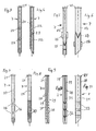
- Have pull-out force. 3 to 11 are examples of profile bars according to the invention 7 for anchoring concrete elements 1 for a concrete protective wall according to the invention shown.
- a profile rod 7 according to FIGS. 3 and 4 is formed from a tube 20 which at one end with a cover plate 21 is connected and is cut obliquely at its second end.
- a profile bar Cross bores 22, 23 are provided in mutually perpendicular directions. there form when driving such a profile bar 7 into the ground via the Cross bores 22, 23 bridges through which the profile rod is pulled out of the Opposed increased resistance underground.
- a profile rod 7 according to FIGS. 5 and 6 is made of a profile tube 24 with a rectangular cross section formed, which is connected at one end to a cover plate 21 and at its second The end is cut obliquely to drive the profile bar 7 into the ground facilitate.
- the profile rod 7 with the longitudinal and Narrow sides of the profile tube 24 laterally projecting V-shaped and up to, or Cover plate 21 to open cross struts 24.
- These cross struts 24 cause one very significant difference in the resistance of the profile bar when ramming and when Pulling out a longitudinal movement opposed to the surface.
- the cross struts 24 also increase the resistance when plowing through the ground in the event of an impact Vehicle to the concrete protective wall according to the invention and thus the efficiency of the same.
- a profile rod 7 In the embodiment of a profile rod 7 according to FIG. 7, it is made of a tube 20 formed, which is connected at one end to a cover plate 21 and at its second end is cut off at an angle. In this embodiment, the pull-out force is increased Dents 26 provided that increase the pull-out resistance.
- the embodiment of a profile bar 7 according to FIG. 8 differs from that 7 in that instead of the dents 27 in the lower half of the profile bar 7 to the outside protruding ribs 27 are provided, which are inclined upwards or towards the cover plate 21 run inclined.
- the profile rod 7 is formed by a 1-profile.
- a cover plate 21 is attached to one end of the profile rod 7 and in the area of the secondly, this I-profile is cut off at an angle to ram it into the ground to facilitate.
- the flanges 29 of the 1-section 28 with notches 30 which are open at the edge and run obliquely against the inclined end of the profiled rod 7 provided, the remaining flange areas between the notches 30 similar to that Teeth of a saw blade can be crossed against each other. Through these notches 30 Such a profile bar makes pulling it out of the ground a very significant one Resistance to.
- the profile bar 7 is also through an I-profile 28 formed, with a cover plate 21 attached to one end and the second end is cut off at an angle.
Landscapes
- Engineering & Computer Science (AREA)
- Architecture (AREA)
- Civil Engineering (AREA)
- Structural Engineering (AREA)
- Refuge Islands, Traffic Blockers, Or Guard Fence (AREA)
Abstract
Description
Claims (14)
- Betonschutzwand, die durch vorgeformte Betonteile (1) gebildet ist, die mit einem eine im wesentlichen ebene Aufstandsfläche (6) aufweisenden Fußteil (3) von dem aus ein gegenüber dem Fußteil (3) schmälerer Wandteil (4) aufragt, auf einem Untergrund (2) aufstehen und stirnseitig im wesentlichen aneinander anliegen, wobei Profilstäbe (7) Bohrungen (5) in den Fußteilen (3) durchsetzen und in den Untergrund gerammt sind, dadurch gekennzeichnet, dass die von Profilstäben (7) durchsetzten Bohrungen (5) in den Fußteilen (3) - in Richtung zum Untergrund (2) gesehen - von der einer Fahrbahn zugewandten Seite des Betonteiles (1) weg weisen.
- Betonschutzwand gemäß Anspruch 1, dadurch gekennzeichnet, dass die Bohrung (5) mit der Normalebene (N-N) einen Winkel im Bereich zwischen etwa 10° und etwa 50°, bevorzugt im Bereich zwischen etwa 15° und etwa 40°, insbesondere im Bereich zwischen etwa 20° und etwa 30°, angeordnet ist.
- Betonschutzwand gemäß einem der Ansprüche 1 oder 2, dadurch gekennzeichnet, dass die Länge des in den Untergrund getriebenen Abschnittes der Profilstäbe (7) in Abhängigkeit von der Beschaffenheit des Untergrundes (2) und den zu erwartenden Aufprallenergien gewählt ist.
- Betonschutzwand gemäß Anspruch 1, dadurch gekennzeichnet, dass das Verhältnis der Länge des in den Untergrund getriebenen Abschnittes der Profilstäbe (7) zur Höhe der Betonteile (1) im Bereich zwischen etwa 0,2 und etwa 1,0, bevorzugt im Bereich zwischen etwa 0,3 und etwa 0,9, insbesondere im Bereich zwischen etwa 0,4 und etwa 0,8, ist.
- Betonschutzwand gemäß einem der Ansprüche 1 bis 4, dadurch gekennzeichnet, dass zwischen den Profilstäben (7) und den Wänden der gegebenenfalls unrunden Bohrungen (5) der Betonteile (1) zumindest in Querrichtung des Fußteiles (3) des jeweiligen Betonteiles (1) ein definierter Freiraum vorgesehen ist, der einen ersten Verschiebeweg des Betonelements (1) bestimmt.
- Betonschutzwand gemäß einem der Ansprüche 1 bis 5, dadurch gekennzeichnet, dass die Bohrungen (5) zu beiden Seiten des Wandteiles (4) gegeneinander versetzt angeordnet sind.
- Betonschutzwand gemäß einem der Ansprüche 1 bis 6, dadurch gekennzeichnet, dass die Profilstäbe (7) zumindest abschnittweise mit nach außen gerichteten Vorsprüngen (25, 27, 32) versehen sind.
- Betonschutzwand gemäß Anspruch 7, dadurch gekennzeichnet, dass die Profilstäbe (7) mit V-förmigen nach oben offenen Querstreben (25) versehen sind, wobei die Profilstäbe (7) vorzugsweise einen I-förmigen Querschnitt aufweisen, oder als Profilrohr ausgebildet sind.
- Betonschutzwand gemäß einem der Ansprüche 1 bis 6, dadurch gekennzeichnet, dass die Profilstäbe (7) durch Rohre (20) gebildet sind, die mit Eindellungen (26) versehen sind.
- Betonschutzwand gemäß Anspruch 7, dadurch gekennzeichnet, dass die Profilstäbe (7) mit nach außen vorragenden Rippen (27) versehen sind.
- Betonschutzwand gemäß einem der Ansprüche 1 bis 6, dadurch gekennzeichnet, dass die Profilstäbe (7) durch Rohre gebildet sind, die mit Querbohrungen (22) versehen sind.
- Betonschutzwand gemäß Anspruch 7, dadurch gekennzeichnet, dass die Profilstäbe (7) durch 1-Profile (28) gebildet sind und zumindest abschnittweise die Flansche (29) mit vorzugsweise schräg nach unten zu verlaufenden Kerben (30) versehen sind, wobei die zwischen den Kerben (30) verbleibenden Flanschabschnitte vorzugsweise gegeneinander verschränkt sind.
- Betonschutzwand gemäß Anspruch 7, dadurch gekennzeichnet, dass die Profilstäbe (7) durch 1-Profile (28) gebildet sind und zumindest abschnittweise an dem Steg (31) des I-Profils (28) sich zwischen den Flanschen (29) desselben Vorsprünge (32) angeschweißt sind, die sich schräg nach oben zu erstrecken.
- Betonelement für die Ausbildung einer Betonschutzwand gemäß einem der Ansprüche 1 bis 11.
Applications Claiming Priority (4)
| Application Number | Priority Date | Filing Date | Title |
|---|---|---|---|
| AT982003 | 2003-01-24 | ||
| AT982003 | 2003-01-24 | ||
| AT0208503A AT413832B (de) | 2003-01-24 | 2003-12-23 | Betonschutzwand |
| AT20852003 | 2003-12-23 |
Publications (3)
| Publication Number | Publication Date |
|---|---|
| EP1441073A2 true EP1441073A2 (de) | 2004-07-28 |
| EP1441073A3 EP1441073A3 (de) | 2005-02-02 |
| EP1441073B1 EP1441073B1 (de) | 2011-06-15 |
Family
ID=32597782
Family Applications (1)
| Application Number | Title | Priority Date | Filing Date |
|---|---|---|---|
| EP04450012A Expired - Lifetime EP1441073B1 (de) | 2003-01-24 | 2004-01-19 | Betonschutzwand |
Country Status (2)
| Country | Link |
|---|---|
| EP (1) | EP1441073B1 (de) |
| AT (2) | AT413832B (de) |
Cited By (4)
| Publication number | Priority date | Publication date | Assignee | Title |
|---|---|---|---|---|
| FR2910028A1 (fr) * | 2006-12-19 | 2008-06-20 | Ims Rn Ingenierie Des Mouvemen | Ouvrage de protection destine a interrompre la progression libre de masses mobiles. |
| IT201700101463A1 (it) * | 2017-09-11 | 2019-03-11 | Ticopter Sa | Tassello per barriera stradale |
| IT201800010855A1 (it) * | 2018-12-06 | 2020-06-06 | Tsl Engineering Soc A Responsabilita Limitata | Dispositivo di ancoraggio al terreno per barriere stradali di sicurezza in calcestruzzo |
| WO2023001972A1 (de) * | 2021-07-22 | 2023-01-26 | Delta Bloc International Gmbh | Fahrzeugrückhaltesystem mit einer betonleitwand |
Families Citing this family (2)
| Publication number | Priority date | Publication date | Assignee | Title |
|---|---|---|---|---|
| DE202017003301U1 (de) | 2017-06-24 | 2017-07-26 | ART Engineering GmbH | Leitplankenprotektor |
| US12553205B2 (en) * | 2021-08-09 | 2026-02-17 | Rsg International Corp. | Anchoring system for a traffic barrier |
Citations (3)
| Publication number | Priority date | Publication date | Assignee | Title |
|---|---|---|---|---|
| DE1292156B (de) | 1956-05-14 | 1969-04-10 | Smith Henry Such | Leiteinrichtung aus Platten fuer Fahrbahnen |
| AT388006B (de) | 1986-08-07 | 1989-04-25 | Schuster Franz | Sicherheitsleitvorrichtung zur randbegrenzung von verkehrsflaechen, insbesondere von strassen und fahrbahnen |
| AT393146B (de) | 1989-04-14 | 1991-08-26 | Universale Bau Aktiengesellsch | Betonsockel zur herstellung einer aus aneinandergereihten, mit ihren stirnflaechen aneinanderliegenden betonsockeln gefertigten leiteinrichtung |
Family Cites Families (4)
| Publication number | Priority date | Publication date | Assignee | Title |
|---|---|---|---|---|
| GB821894A (en) * | 1956-05-14 | 1959-10-14 | Henry Such Smith | Roadway guard rail barrier |
| US5302047A (en) * | 1991-04-25 | 1994-04-12 | Texas A&M University System | Pedestrian safety barrier |
| IT1302420B1 (it) * | 1998-08-05 | 2000-09-05 | Autostrade Concess Const | Dispositivi per la decelerazione calibratra dei veicoli urtantiper barriere di sicurezza a profilo new jersey con ancoraggio |
| US20030068199A1 (en) * | 2001-10-09 | 2003-04-10 | Ulislam Mohammed A. | System for anchoring concrete safety barriers on bridges and roads |
-
2003
- 2003-12-23 AT AT0208503A patent/AT413832B/de not_active IP Right Cessation
-
2004
- 2004-01-19 EP EP04450012A patent/EP1441073B1/de not_active Expired - Lifetime
- 2004-01-19 AT AT04450012T patent/ATE513086T1/de active
Patent Citations (3)
| Publication number | Priority date | Publication date | Assignee | Title |
|---|---|---|---|---|
| DE1292156B (de) | 1956-05-14 | 1969-04-10 | Smith Henry Such | Leiteinrichtung aus Platten fuer Fahrbahnen |
| AT388006B (de) | 1986-08-07 | 1989-04-25 | Schuster Franz | Sicherheitsleitvorrichtung zur randbegrenzung von verkehrsflaechen, insbesondere von strassen und fahrbahnen |
| AT393146B (de) | 1989-04-14 | 1991-08-26 | Universale Bau Aktiengesellsch | Betonsockel zur herstellung einer aus aneinandergereihten, mit ihren stirnflaechen aneinanderliegenden betonsockeln gefertigten leiteinrichtung |
Cited By (7)
| Publication number | Priority date | Publication date | Assignee | Title |
|---|---|---|---|---|
| FR2910028A1 (fr) * | 2006-12-19 | 2008-06-20 | Ims Rn Ingenierie Des Mouvemen | Ouvrage de protection destine a interrompre la progression libre de masses mobiles. |
| IT201700101463A1 (it) * | 2017-09-11 | 2019-03-11 | Ticopter Sa | Tassello per barriera stradale |
| EP3453898A1 (de) * | 2017-09-11 | 2019-03-13 | Ticopter SA | Bolzen für strassenschranke |
| IT201800010855A1 (it) * | 2018-12-06 | 2020-06-06 | Tsl Engineering Soc A Responsabilita Limitata | Dispositivo di ancoraggio al terreno per barriere stradali di sicurezza in calcestruzzo |
| WO2020115710A1 (en) * | 2018-12-06 | 2020-06-11 | Tsl Engineering - Societa' A Responsabilita' Limitata | Device for anchoring road safety barriers made of concrete to the ground |
| WO2023001972A1 (de) * | 2021-07-22 | 2023-01-26 | Delta Bloc International Gmbh | Fahrzeugrückhaltesystem mit einer betonleitwand |
| AT525304A1 (de) * | 2021-07-22 | 2023-02-15 | Delta Bloc Int Gmbh | Fahrzeugrückhaltesystem mit einer betonleitwand |
Also Published As
| Publication number | Publication date |
|---|---|
| EP1441073B1 (de) | 2011-06-15 |
| AT413832B (de) | 2006-06-15 |
| ATE513086T1 (de) | 2011-07-15 |
| EP1441073A3 (de) | 2005-02-02 |
| ATA20852003A (de) | 2005-10-15 |
Similar Documents
| Publication | Publication Date | Title |
|---|---|---|
| DE69816898T2 (de) | Bodenverankerung für ein Schutzplanken-Ende | |
| DE69406930T2 (de) | Leichte leitschranken für brücken | |
| EP3441527B1 (de) | Absperrvorrichtung zum verhindern der durchfahrt von landfahrzeugen | |
| EP0874940B1 (de) | Schutzplankenanordnung | |
| CH707671B1 (de) | Stützmauerelement und Stützmauer aus Stützmauerelementen. | |
| DE2844748C2 (de) | Entwässerungsrinne | |
| EP0641893A1 (de) | Betonleitwand | |
| EP4083324B1 (de) | Mobile fahrzeugsperre zur aufstellung auf einem ebenen untergrund und verfahren zum aufstellen dieser mobilen fahrzeugsperre auf einem harten untergrund | |
| WO2018145688A1 (de) | Mobile auffahrt-zufahrtssperre | |
| AT413832B (de) | Betonschutzwand | |
| EP4257764A1 (de) | Entwässerungsvorrichtung für eine bauseitige montage und entwässerungssystem | |
| EP1997957B1 (de) | Fahrzeug-Rückhaltesystem an Verkehrswegen | |
| EP0310754A2 (de) | Trennvorrichtung | |
| DE3012680A1 (de) | Stahlschutzplanke | |
| DE102008026661B4 (de) | Verkehrsleitwand | |
| CH683355A5 (de) | Leichtbau-Schallschutzkonstruktion. | |
| EP2075377A2 (de) | Schutzeinrichtung an Verkehrswegen | |
| EP1026327B1 (de) | Anpralldämpfer | |
| DE19631275C1 (de) | Fangedamm | |
| CH678872A5 (de) | ||
| DE202010005481U1 (de) | Passive Schutzeinrichtung | |
| DE8628958U1 (de) | Bauelementensatz für die Herstellung von Raumgitterwänden | |
| DE202020002551U1 (de) | Kombiniertes Sicht-/Lärmschutz- und Fahrzeugrückhaltesystem | |
| EP4729694A1 (de) | Ingenieurbauwerk für verkehrsanlagen | |
| DE9420696U1 (de) | Gurtung für eine mit Spundbohlen erstellte Spundwand |
Legal Events
| Date | Code | Title | Description |
|---|---|---|---|
| PUAI | Public reference made under article 153(3) epc to a published international application that has entered the european phase |
Free format text: ORIGINAL CODE: 0009012 |
|
| AK | Designated contracting states |
Kind code of ref document: A2 Designated state(s): AT BE BG CH CY CZ DE DK EE ES FI FR GB GR HU IE IT LI LU MC NL PT RO SE SI SK TR |
|
| AX | Request for extension of the european patent |
Extension state: AL LT LV MK |
|
| RIN1 | Information on inventor provided before grant (corrected) |
Inventor name: DIPL.ING. BARNAS ALEXANDER Inventor name: REDLBERGER ALFRED |
|
| PUAL | Search report despatched |
Free format text: ORIGINAL CODE: 0009013 |
|
| AK | Designated contracting states |
Kind code of ref document: A3 Designated state(s): AT BE BG CH CY CZ DE DK EE ES FI FR GB GR HU IE IT LI LU MC NL PT RO SE SI SK TR |
|
| AX | Request for extension of the european patent |
Extension state: AL LT LV MK |
|
| 17P | Request for examination filed |
Effective date: 20050802 |
|
| AKX | Designation fees paid |
Designated state(s): AT BE BG CH CY CZ DE DK EE ES FI FR GB GR HU IE IT LI LU MC NL PT RO SE SI SK TR |
|
| 17Q | First examination report despatched |
Effective date: 20090216 |
|
| GRAP | Despatch of communication of intention to grant a patent |
Free format text: ORIGINAL CODE: EPIDOSNIGR1 |
|
| GRAS | Grant fee paid |
Free format text: ORIGINAL CODE: EPIDOSNIGR3 |
|
| GRAA | (expected) grant |
Free format text: ORIGINAL CODE: 0009210 |
|
| AK | Designated contracting states |
Kind code of ref document: B1 Designated state(s): AT BE BG CH CY CZ DE DK EE ES FI FR GB GR HU IE IT LI LU MC NL PT RO SE SI SK TR |
|
| REG | Reference to a national code |
Ref country code: CH Ref legal event code: EP Ref country code: GB Ref legal event code: FG4D Free format text: NOT ENGLISH |
|
| REG | Reference to a national code |
Ref country code: IE Ref legal event code: FG4D Free format text: LANGUAGE OF EP DOCUMENT: GERMAN |
|
| REG | Reference to a national code |
Ref country code: DE Ref legal event code: R096 Ref document number: 502004012603 Country of ref document: DE Effective date: 20110721 |
|
| REG | Reference to a national code |
Ref country code: NL Ref legal event code: T3 |
|
| REG | Reference to a national code |
Ref country code: CH Ref legal event code: NV Representative=s name: BOVARD AG |
|
| PG25 | Lapsed in a contracting state [announced via postgrant information from national office to epo] |
Ref country code: SE Free format text: LAPSE BECAUSE OF FAILURE TO SUBMIT A TRANSLATION OF THE DESCRIPTION OR TO PAY THE FEE WITHIN THE PRESCRIBED TIME-LIMIT Effective date: 20110615 |
|
| REG | Reference to a national code |
Ref country code: ES Ref legal event code: FG2A Ref document number: 2367777 Country of ref document: ES Kind code of ref document: T3 Effective date: 20111108 |
|
| PG25 | Lapsed in a contracting state [announced via postgrant information from national office to epo] |
Ref country code: CY Free format text: LAPSE BECAUSE OF FAILURE TO SUBMIT A TRANSLATION OF THE DESCRIPTION OR TO PAY THE FEE WITHIN THE PRESCRIBED TIME-LIMIT Effective date: 20110615 Ref country code: FI Free format text: LAPSE BECAUSE OF FAILURE TO SUBMIT A TRANSLATION OF THE DESCRIPTION OR TO PAY THE FEE WITHIN THE PRESCRIBED TIME-LIMIT Effective date: 20110615 Ref country code: GR Free format text: LAPSE BECAUSE OF FAILURE TO SUBMIT A TRANSLATION OF THE DESCRIPTION OR TO PAY THE FEE WITHIN THE PRESCRIBED TIME-LIMIT Effective date: 20110916 Ref country code: SI Free format text: LAPSE BECAUSE OF FAILURE TO SUBMIT A TRANSLATION OF THE DESCRIPTION OR TO PAY THE FEE WITHIN THE PRESCRIBED TIME-LIMIT Effective date: 20110615 |
|
| REG | Reference to a national code |
Ref country code: IE Ref legal event code: FD4D |
|
| PG25 | Lapsed in a contracting state [announced via postgrant information from national office to epo] |
Ref country code: PT Free format text: LAPSE BECAUSE OF FAILURE TO SUBMIT A TRANSLATION OF THE DESCRIPTION OR TO PAY THE FEE WITHIN THE PRESCRIBED TIME-LIMIT Effective date: 20111017 Ref country code: IE Free format text: LAPSE BECAUSE OF FAILURE TO SUBMIT A TRANSLATION OF THE DESCRIPTION OR TO PAY THE FEE WITHIN THE PRESCRIBED TIME-LIMIT Effective date: 20110615 Ref country code: EE Free format text: LAPSE BECAUSE OF FAILURE TO SUBMIT A TRANSLATION OF THE DESCRIPTION OR TO PAY THE FEE WITHIN THE PRESCRIBED TIME-LIMIT Effective date: 20110615 |
|
| PG25 | Lapsed in a contracting state [announced via postgrant information from national office to epo] |
Ref country code: RO Free format text: LAPSE BECAUSE OF FAILURE TO SUBMIT A TRANSLATION OF THE DESCRIPTION OR TO PAY THE FEE WITHIN THE PRESCRIBED TIME-LIMIT Effective date: 20110615 Ref country code: SK Free format text: LAPSE BECAUSE OF FAILURE TO SUBMIT A TRANSLATION OF THE DESCRIPTION OR TO PAY THE FEE WITHIN THE PRESCRIBED TIME-LIMIT Effective date: 20110615 |
|
| PLBE | No opposition filed within time limit |
Free format text: ORIGINAL CODE: 0009261 |
|
| STAA | Information on the status of an ep patent application or granted ep patent |
Free format text: STATUS: NO OPPOSITION FILED WITHIN TIME LIMIT |
|
| 26N | No opposition filed |
Effective date: 20120316 |
|
| PG25 | Lapsed in a contracting state [announced via postgrant information from national office to epo] |
Ref country code: DK Free format text: LAPSE BECAUSE OF FAILURE TO SUBMIT A TRANSLATION OF THE DESCRIPTION OR TO PAY THE FEE WITHIN THE PRESCRIBED TIME-LIMIT Effective date: 20110615 |
|
| REG | Reference to a national code |
Ref country code: DE Ref legal event code: R097 Ref document number: 502004012603 Country of ref document: DE Effective date: 20120316 |
|
| PG25 | Lapsed in a contracting state [announced via postgrant information from national office to epo] |
Ref country code: MC Free format text: LAPSE BECAUSE OF NON-PAYMENT OF DUE FEES Effective date: 20120131 |
|
| REG | Reference to a national code |
Ref country code: AT Ref legal event code: MM01 Ref document number: 513086 Country of ref document: AT Kind code of ref document: T Effective date: 20120119 |
|
| PG25 | Lapsed in a contracting state [announced via postgrant information from national office to epo] |
Ref country code: AT Free format text: LAPSE BECAUSE OF NON-PAYMENT OF DUE FEES Effective date: 20120119 Ref country code: BG Free format text: LAPSE BECAUSE OF FAILURE TO SUBMIT A TRANSLATION OF THE DESCRIPTION OR TO PAY THE FEE WITHIN THE PRESCRIBED TIME-LIMIT Effective date: 20110915 |
|
| PG25 | Lapsed in a contracting state [announced via postgrant information from national office to epo] |
Ref country code: LU Free format text: LAPSE BECAUSE OF NON-PAYMENT OF DUE FEES Effective date: 20120119 |
|
| PG25 | Lapsed in a contracting state [announced via postgrant information from national office to epo] |
Ref country code: HU Free format text: LAPSE BECAUSE OF FAILURE TO SUBMIT A TRANSLATION OF THE DESCRIPTION OR TO PAY THE FEE WITHIN THE PRESCRIBED TIME-LIMIT Effective date: 20040119 |
|
| REG | Reference to a national code |
Ref country code: FR Ref legal event code: PLFP Year of fee payment: 13 |
|
| REG | Reference to a national code |
Ref country code: FR Ref legal event code: PLFP Year of fee payment: 14 |
|
| REG | Reference to a national code |
Ref country code: FR Ref legal event code: PLFP Year of fee payment: 15 |
|
| REG | Reference to a national code |
Ref country code: ES Ref legal event code: PC2A Owner name: DELTA BLOC INTERNATIONAL GMBH Effective date: 20200417 |
|
| REG | Reference to a national code |
Ref country code: CH Ref legal event code: PUE Owner name: DELTA BLOC INTERNATIONAL GMBH, AT Free format text: FORMER OWNER: MABA FERTIGTEILINDUSTRIE GMBH, AT |
|
| PGFP | Annual fee paid to national office [announced via postgrant information from national office to epo] |
Ref country code: IT Payment date: 20200122 Year of fee payment: 17 Ref country code: ES Payment date: 20200219 Year of fee payment: 17 Ref country code: NL Payment date: 20200122 Year of fee payment: 17 |
|
| PGFP | Annual fee paid to national office [announced via postgrant information from national office to epo] |
Ref country code: CZ Payment date: 20200110 Year of fee payment: 17 Ref country code: CH Payment date: 20200127 Year of fee payment: 17 Ref country code: BE Payment date: 20200122 Year of fee payment: 17 |
|
| REG | Reference to a national code |
Ref country code: DE Ref legal event code: R081 Ref document number: 502004012603 Country of ref document: DE Owner name: DELTA BLOC INTERNATIONAL GMBH, AT Free format text: FORMER OWNER: MABA FERTIGTEILINDUSTRIE GMBH, WOELLERSDORF, AT |
|
| REG | Reference to a national code |
Ref country code: BE Ref legal event code: PD Owner name: DELTA BLOC INTERNATIONAL GMBH; AT Free format text: DETAILS ASSIGNMENT: CHANGE OF OWNER(S), CESSION; FORMER OWNER NAME: MABA FERTIGTEILINDUSTRIE GMBH Effective date: 20200404 |
|
| PGFP | Annual fee paid to national office [announced via postgrant information from national office to epo] |
Ref country code: FR Payment date: 20200123 Year of fee payment: 17 |
|
| REG | Reference to a national code |
Ref country code: NL Ref legal event code: PD Owner name: DELTA BLOC INTERNATIONAL GMBH; AT Free format text: DETAILS ASSIGNMENT: CHANGE OF OWNER(S), ASSIGNMENT; FORMER OWNER NAME: MABA FERTIGTEILINDUSTRIE GMBH Effective date: 20200604 |
|
| REG | Reference to a national code |
Ref country code: GB Ref legal event code: 732E Free format text: REGISTERED BETWEEN 20200709 AND 20200715 |
|
| REG | Reference to a national code |
Ref country code: CH Ref legal event code: PL |
|
| REG | Reference to a national code |
Ref country code: NL Ref legal event code: MM Effective date: 20210201 |
|
| REG | Reference to a national code |
Ref country code: BE Ref legal event code: MM Effective date: 20210131 |
|
| PG25 | Lapsed in a contracting state [announced via postgrant information from national office to epo] |
Ref country code: NL Free format text: LAPSE BECAUSE OF NON-PAYMENT OF DUE FEES Effective date: 20210201 Ref country code: FR Free format text: LAPSE BECAUSE OF NON-PAYMENT OF DUE FEES Effective date: 20210131 Ref country code: CZ Free format text: LAPSE BECAUSE OF NON-PAYMENT OF DUE FEES Effective date: 20210119 |
|
| PG25 | Lapsed in a contracting state [announced via postgrant information from national office to epo] |
Ref country code: LI Free format text: LAPSE BECAUSE OF NON-PAYMENT OF DUE FEES Effective date: 20210131 Ref country code: CH Free format text: LAPSE BECAUSE OF NON-PAYMENT OF DUE FEES Effective date: 20210131 |
|
| REG | Reference to a national code |
Ref country code: ES Ref legal event code: FD2A Effective date: 20220422 |
|
| PG25 | Lapsed in a contracting state [announced via postgrant information from national office to epo] |
Ref country code: IT Free format text: LAPSE BECAUSE OF NON-PAYMENT OF DUE FEES Effective date: 20210119 |
|
| PG25 | Lapsed in a contracting state [announced via postgrant information from national office to epo] |
Ref country code: ES Free format text: LAPSE BECAUSE OF NON-PAYMENT OF DUE FEES Effective date: 20210120 Ref country code: BE Free format text: LAPSE BECAUSE OF NON-PAYMENT OF DUE FEES Effective date: 20210131 |
|
| PGFP | Annual fee paid to national office [announced via postgrant information from national office to epo] |
Ref country code: TR Payment date: 20230117 Year of fee payment: 20 Ref country code: GB Payment date: 20230124 Year of fee payment: 20 Ref country code: DE Payment date: 20230119 Year of fee payment: 20 |
|
| P01 | Opt-out of the competence of the unified patent court (upc) registered |
Effective date: 20230515 |
|
| REG | Reference to a national code |
Ref country code: DE Ref legal event code: R071 Ref document number: 502004012603 Country of ref document: DE |
|
| REG | Reference to a national code |
Ref country code: GB Ref legal event code: PE20 Expiry date: 20240118 |
|
| PG25 | Lapsed in a contracting state [announced via postgrant information from national office to epo] |
Ref country code: GB Free format text: LAPSE BECAUSE OF EXPIRATION OF PROTECTION Effective date: 20240118 |