EP1441088A2 - Multifunktionelles Gerüst - Google Patents
Multifunktionelles Gerüst Download PDFInfo
- Publication number
- EP1441088A2 EP1441088A2 EP04380008A EP04380008A EP1441088A2 EP 1441088 A2 EP1441088 A2 EP 1441088A2 EP 04380008 A EP04380008 A EP 04380008A EP 04380008 A EP04380008 A EP 04380008A EP 1441088 A2 EP1441088 A2 EP 1441088A2
- Authority
- EP
- European Patent Office
- Prior art keywords
- scaffolding
- securing
- crossbars
- column
- multifunctional
- Prior art date
- Legal status (The legal status is an assumption and is not a legal conclusion. Google has not performed a legal analysis and makes no representation as to the accuracy of the status listed.)
- Withdrawn
Links
Images


Classifications
-
- E—FIXED CONSTRUCTIONS
- E04—BUILDING
- E04G—SCAFFOLDING; FORMS; SHUTTERING; BUILDING IMPLEMENTS OR AIDS, OR THEIR USE; HANDLING BUILDING MATERIALS ON THE SITE; REPAIRING, BREAKING-UP OR OTHER WORK ON EXISTING BUILDINGS
- E04G3/00—Scaffolds essentially supported by building constructions, e.g. adjustable in height
- E04G3/18—Scaffolds essentially supported by building constructions, e.g. adjustable in height supported by cantilevers or other provisions mounted in openings in the building, e.g. window openings
Definitions
- the present invention refers to scaffolding, of the type used in building construction, which is especially suitable for use in cantilevers or eaves of roofs.
- the object of the invention is to obtain a work platform, properly protected, which projects sufficiently outwards with respect to what should be the general front surface of the building facade as to be able to comfortably work on a roof or any other type of cantilever.
- the first of them consists in establishing a structure that ascends from the ground along the facade, based on vertical stanchions, horizontal crossbars and stabilising struts, a solution that allows working at any level of the building, but with which the scaffolding platforms remains attached to said facade, since the structure must be fixed to this latter to provide the necessary safety to the scaffolding, especially as its height increases, with the result that the scaffolding does not offer a suitable work surface, when the work must be carried out at the level of the eaves of the building or of any another type of cantilever.
- the second solution structurally simpler, consists in using mobile scaffolding, which is suspended from the structure by cantilever from the roof, and which is capable of vertically passing over the façade, with the array of support cables and pulleys, said cables winding and unwinding during the movement of the scaffolding whether motorised or manually.
- this solution does not also allow working with ease on the eaves of the building, since the scaffolding is actually suspended from said eaves and located beneath them.
- the scaffolding that the invention proposes fully and satisfactory solves the problems previously set out, in as much as it allows a cantilevered work platform to be established, at any height level required, and projecting outwards from the building to any extent that might be necessary.
- said scaffolding is structured using at least one pair of telescopic columns destined to join at pressure in the space set out between two adjacent cast structures, each of the said columns having anti-slip end pads, to assure a correct securing against said cast structures.
- each of these columns be double, structured by means of two parallel vertical telescopic tubes, to which said anti-slip pads are socket attached at each of their ends.
- every column incorporates at least one auxiliary section, properly welded to its fixed sector and having a longitudinal alignment of holes, to which crossbars, that extend towards the exterior of the building, can be selectively attached, using bolts or similar of an appropriate length, and that constitute the support base for the scaffolding platform; a platform that in this way can remain positioned at any height level along the columns that sustain it.
- Such crossbars incorporate other openings at their free end, destined in turn for securing the vertical stanchions that, occupying the end exterior position of the scaffolding, are in turn intended to form part of a protective rail.
- these crossbars When the length of the said crossbars, by being excessive, makes it advisable, these can incorporate intermediate openings for the attachment, in an similar manner, of oblique bracing bars of the structure, that assist in its stabilisation.
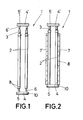
- a column (1) is involved as a fundamental element, and which will repeat itself two or more times along the scaffolding, each column (1) being structured by means of a pair of parallel tubes (2) which finish off at their upper end in respective telescopic tubes (3), which allow the effective length of the column to be regulated at will, the pair of tubes (2) receiving at their lower end a pad (4) provided with an anti-slip surfacing (5) in its external face and of a pair of rods (6) in its internal face for their insertion into the corresponding end of the tubes (2); whereas the top tubes (3) similarly receive another shoe (4'), with its corresponding anti-slip surfacing (5') in its external face and similar rods (6') that socket attach with said tubes (3); both the tubes (2-3) and the rods (6) of the pads having respective holes (8) for definitive securing between these parts, with the assistance of respective catches.
- Each column is supplemented with at least one auxiliary section (7), longitudinally attached to one of the tubes (2), acting on most of the its length, as is seen in figure 2; these auxiliary sections (7) having holes (8), evenly distributed, that in turn allow the attachment to each column, at any level of height required, of a series of crossbars (9) that form part of the scaffolding.
- each column (1) will incorporate two auxiliary sections (7-7'), suitably stabilized opposite the tubes (2) that form part of it, for a greater structural rigidity of the scaffolding as regards the attachment of the crossbars (9) to the columns, as, in turn, is noted on examining figure 3.
- the lower pad (4) in turn has a pair of holes (10), near its ends, that allow the fixation of a crossbar (9') at this lower end level of the columns (1), as also is seen in figure 3.
- the crossbars (9-9') incorporate in their free end respective holes (11) for securing vertical stanchions (12) that similarly form part of the scaffolding, specifically forming part of its barrier or protection rail, to which effect said vertical stanchions (12) can be provided with brackets (13), adequately positioned in height, forming with the stanchions (12) concave channeling, orientated upwards, in which crossbeams of any appropriate material, which actually form the rail, can be placed.
- crossbars (9-9') be placed at low level and/or at intermediate level and/or at several intermediate levels, as has been shown in the figures; likewise also that such crossbars are simple or double, according to the structural rigidity sought in each case, since this will be variable depending not only the actual length of the crossbars (9-9') but also on whether these act exclusively as a means of lateral containment or as supports for the work platform of the scaffolding.
- the columns (1) can have solely one auxiliary section (7), as has also been shown in figure 5.
- the scaffolding is multifunctional given the wide range of possibilities that its removable structure offers.
Landscapes
- Engineering & Computer Science (AREA)
- Architecture (AREA)
- Mechanical Engineering (AREA)
- Civil Engineering (AREA)
- Structural Engineering (AREA)
- Ladders (AREA)
- Movable Scaffolding (AREA)
- Mutual Connection Of Rods And Tubes (AREA)
Applications Claiming Priority (2)
| Application Number | Priority Date | Filing Date | Title |
|---|---|---|---|
| ES200300173U | 2003-01-24 | ||
| ES200300173U ES1053926Y (es) | 2003-01-24 | 2003-01-24 | Andamio multifuncional. |
Publications (2)
| Publication Number | Publication Date |
|---|---|
| EP1441088A2 true EP1441088A2 (de) | 2004-07-28 |
| EP1441088A3 EP1441088A3 (de) | 2004-12-08 |
Family
ID=8502972
Family Applications (1)
| Application Number | Title | Priority Date | Filing Date |
|---|---|---|---|
| EP04380008A Withdrawn EP1441088A3 (de) | 2003-01-24 | 2004-01-12 | Multifunktionelles Gerüst |
Country Status (2)
| Country | Link |
|---|---|
| EP (1) | EP1441088A3 (de) |
| ES (1) | ES1053926Y (de) |
Cited By (5)
| Publication number | Priority date | Publication date | Assignee | Title |
|---|---|---|---|---|
| KR100901016B1 (ko) | 2009-02-28 | 2009-06-23 | (주)예원엔지니어링 종합건축사사무소 | 건축물의 외벽 비계 안전 브라켓 |
| CN102966240A (zh) * | 2012-11-30 | 2013-03-13 | 福建省第五建筑工程公司 | 一种高空钢筋混凝土外悬挑结构的施工方法 |
| CN107227814A (zh) * | 2017-06-19 | 2017-10-03 | 中国建筑第二工程局有限公司 | 一种大悬挑混凝土结构分段施工方法 |
| CN110900530A (zh) * | 2018-09-17 | 2020-03-24 | 中国三冶集团有限公司 | 顶板膨胀螺栓孔开孔支撑器 |
| CN111099530A (zh) * | 2020-01-16 | 2020-05-05 | 河南江河特种车辆科技有限公司 | 一种剪叉式高空作业平台 |
Family Cites Families (6)
| Publication number | Priority date | Publication date | Assignee | Title |
|---|---|---|---|---|
| BE534177A (de) * | ||||
| FR1234261A (fr) * | 1959-05-14 | 1960-10-17 | Console garde-corps associée à un étai de coffrage | |
| FR2307936A1 (fr) * | 1975-04-18 | 1976-11-12 | Deleau Daniel | Echafaudage de securite |
| FR2347507A2 (fr) * | 1976-04-08 | 1977-11-04 | Deleau Daniel | Echafaudage a nacelle reglable |
| DE3539653A1 (de) * | 1985-11-08 | 1987-05-21 | Karl Frank | Arbeitsgeruest, das im fensterbereich von gebaeudewaenden aufstuetzbar ist |
| AUPN087395A0 (en) * | 1995-01-31 | 1995-02-23 | Preston, John Clement | Suspendable container |
-
2003
- 2003-01-24 ES ES200300173U patent/ES1053926Y/es not_active Expired - Fee Related
-
2004
- 2004-01-12 EP EP04380008A patent/EP1441088A3/de not_active Withdrawn
Cited By (6)
| Publication number | Priority date | Publication date | Assignee | Title |
|---|---|---|---|---|
| KR100901016B1 (ko) | 2009-02-28 | 2009-06-23 | (주)예원엔지니어링 종합건축사사무소 | 건축물의 외벽 비계 안전 브라켓 |
| CN102966240A (zh) * | 2012-11-30 | 2013-03-13 | 福建省第五建筑工程公司 | 一种高空钢筋混凝土外悬挑结构的施工方法 |
| CN102966240B (zh) * | 2012-11-30 | 2014-02-19 | 福建省第五建筑工程公司 | 一种高空钢筋混凝土外悬挑结构的施工方法 |
| CN107227814A (zh) * | 2017-06-19 | 2017-10-03 | 中国建筑第二工程局有限公司 | 一种大悬挑混凝土结构分段施工方法 |
| CN110900530A (zh) * | 2018-09-17 | 2020-03-24 | 中国三冶集团有限公司 | 顶板膨胀螺栓孔开孔支撑器 |
| CN111099530A (zh) * | 2020-01-16 | 2020-05-05 | 河南江河特种车辆科技有限公司 | 一种剪叉式高空作业平台 |
Also Published As
| Publication number | Publication date |
|---|---|
| ES1053926Y (es) | 2003-09-16 |
| EP1441088A3 (de) | 2004-12-08 |
| ES1053926U (es) | 2003-06-01 |
Similar Documents
| Publication | Publication Date | Title |
|---|---|---|
| AU2008215260B2 (en) | A formwork system | |
| KR101654483B1 (ko) | 안전발판을 포함한 건축용 비계장치 | |
| JP4260106B2 (ja) | 作業架台 | |
| CZ282526B6 (cs) | Způsob a zařízení pro montáž vedení hydraulického výtahu | |
| US20120006621A1 (en) | Movable modular scaffold system for building works and method to form it | |
| RU2400609C2 (ru) | Комплексная система обеспечения техники безопасности в строительстве | |
| CZ353596A3 (en) | Travelling scaffold | |
| AU2006200200A1 (en) | Hook-On Scaffold | |
| DK2698486T3 (en) | Vertical support structure for roof security fencing system | |
| DE3611431C2 (de) | Gerüststützeinrichtung für Gehwegüberbrückungen | |
| US20240093516A1 (en) | Pre-assembled climbing scaffold with movement system with cart and gang panel | |
| DE10121957A1 (de) | Absturzsicherung für Baugerüste | |
| EP1215354A2 (de) | Vorrichtung zum Schutz von Personen, die auf Dächern von Gebäuden oder dergleichen arbeiten, und zum Tragen von Arbeitern während der Arbeiten an Dachrändern | |
| JP4037964B2 (ja) | 組立式足場台 | |
| JP4986419B2 (ja) | 仮設階段 | |
| JP5437164B2 (ja) | テント倉庫 | |
| KR102893910B1 (ko) | 확장이 가능한 고소작업대 | |
| EP0934450A1 (de) | Gerüststützelement | |
| RU2292431C2 (ru) | Рабочие подмости | |
| RU2809450C1 (ru) | Кронштейн для установки навесной площадки | |
| KR200493327Y1 (ko) | 호이스트용 방호선반 | |
| KR200400391Y1 (ko) | 추락방지대가 설치되는 비계틀 설치구조 | |
| JP7051084B2 (ja) | 仮設足場用長さ調整手摺構造 | |
| WO2025233178A1 (en) | Height extender and ancillary components for a work platform | |
| KR20060111907A (ko) | 건축용 안전망 지지장치 |
Legal Events
| Date | Code | Title | Description |
|---|---|---|---|
| PUAI | Public reference made under article 153(3) epc to a published international application that has entered the european phase |
Free format text: ORIGINAL CODE: 0009012 |
|
| AK | Designated contracting states |
Kind code of ref document: A2 Designated state(s): AT BE BG CH CY CZ DE DK EE ES FI FR GB GR HU IE IT LI LU MC NL PT RO SE SI SK TR |
|
| AX | Request for extension of the european patent |
Extension state: AL LT LV MK |
|
| PUAL | Search report despatched |
Free format text: ORIGINAL CODE: 0009013 |
|
| AK | Designated contracting states |
Kind code of ref document: A3 Designated state(s): AT BE BG CH CY CZ DE DK EE ES FI FR GB GR HU IE IT LI LU MC NL PT RO SE SI SK TR |
|
| AX | Request for extension of the european patent |
Extension state: AL LT LV MK |
|
| 17P | Request for examination filed |
Effective date: 20050608 |
|
| AKX | Designation fees paid |
Designated state(s): AT BE BG CH CY CZ DE DK EE ES FI FR GB GR HU IE IT LI LU MC NL PT RO SE SI SK TR |
|
| STAA | Information on the status of an ep patent application or granted ep patent |
Free format text: STATUS: THE APPLICATION IS DEEMED TO BE WITHDRAWN |
|
| 18D | Application deemed to be withdrawn |
Effective date: 20080801 |