EP1441194B1 - Instrument de mesure - Google Patents
Instrument de mesure Download PDFInfo
- Publication number
- EP1441194B1 EP1441194B1 EP04001338.5A EP04001338A EP1441194B1 EP 1441194 B1 EP1441194 B1 EP 1441194B1 EP 04001338 A EP04001338 A EP 04001338A EP 1441194 B1 EP1441194 B1 EP 1441194B1
- Authority
- EP
- European Patent Office
- Prior art keywords
- arm
- short arm
- short
- proximal
- measuring instrument
- Prior art date
- Legal status (The legal status is an assumption and is not a legal conclusion. Google has not performed a legal analysis and makes no representation as to the accuracy of the status listed.)
- Expired - Lifetime
Links
- 230000007246 mechanism Effects 0.000 claims description 39
- 230000001360 synchronised effect Effects 0.000 claims description 16
- 239000000523 sample Substances 0.000 description 20
- 238000009434 installation Methods 0.000 description 11
- 238000005259 measurement Methods 0.000 description 8
- 230000004048 modification Effects 0.000 description 3
- 238000012986 modification Methods 0.000 description 3
- 230000008901 benefit Effects 0.000 description 2
- 230000005540 biological transmission Effects 0.000 description 2
- 230000009467 reduction Effects 0.000 description 2
- 230000008439 repair process Effects 0.000 description 2
- 238000000034 method Methods 0.000 description 1
- 230000008569 process Effects 0.000 description 1
- 239000007787 solid Substances 0.000 description 1
Images




Classifications
-
- G—PHYSICS
- G01—MEASURING; TESTING
- G01B—MEASURING LENGTH, THICKNESS OR SIMILAR LINEAR DIMENSIONS; MEASURING ANGLES; MEASURING AREAS; MEASURING IRREGULARITIES OF SURFACES OR CONTOURS
- G01B5/00—Measuring arrangements characterised by the use of mechanical techniques
- G01B5/004—Measuring arrangements characterised by the use of mechanical techniques for measuring coordinates of points
Definitions
- the present invention relates to a measuring instrument for measuring a dimension of a workpiece based on a position of a detector.
- measuring instruments having an arm provided with a probe (detector) and a support for supporting the arm in a manner movable in the axial direction thereof have been known, the measuring instruments measuring a dimension of a workpiece based on the position of the probe (for instance, see Japanese Utility Model Laid-Open Publication No. Hei4-45911 [ Fig. 7 ]).
- the measuring instrument shown in the Japanese Utility Model Publication has a column movable in a direction on a horizontal surface of a base, a beam supported by the column in a manner movable in perpendicular direction of the horizontal surface, a slider supported by the beam in a manner movable in a direction orthogonal to the moving direction of the column and the beam, an arm provided on the slider and a probe provided on the tip end of the arm.
- the column, the beam and the slider are moved to bring the probe into contact with the workpiece.
- a measuring instrument 7 shown in Fig. 7 has been known as one of horizontal two-dimensional measuring instruments.
- the measuring instrument 7 has a base 71, a column 72 vertically mounted on a horizontal surface of the base 71, a support 73 elevatably supported by the column 72, a slider 74 supported by the support 73 in a manner movable in a direction orthogonal to the moving direction of the support 73, an arm 74 provided on the slider 74 and a probe (detector: not shown) provided on the tip end of the arm 75.
- the slider 74 is moved to bring the probe into contact with the workpiece.
- installation space of the Japanese Utility Model Laid-Open Publication No. Hei4-45911 and the measuring instrument 7 has to be twice or more as wide as the stroke of the probe (referred to detector stroke hereinafter).
- the slider 74 is also moved by the detector stroke S1, so that the length of the support 73 for supporting the slider 74 has to be at least equal to the sum of the detector stroke S1 and the length X of the slider 74.
- the installation space W7 of the measuring instrument 7 has to be 2(S1)+X or more, i.e. twice or more as wide as the detector stroke S1.
- a measuring instrument having the features according to the preamble of claim 1 is disclosed in DE 2413335A and WO 02/101329 A.
- An object of the present invention is to provide a measuring instrument capable of reducing the installation space and the measurement time thereof.
- the object is achieved by measuring instrument as set forth in claim 1.
- a measuring instrument has: an arm provided with a detector at a distal end thereof; and a support for supporting the arm in a manner movable in the axial direction thereof, the measuring instrument measuring a dimension of a workpiece based on the position of the detector, in which the arm includes a plurality of short arms sequentially disposed on the support, the short arm being respectively supported in a manner movable relative to a former component thereof, and in which the measuring instrument has drivers for independently moving a proximal short arm and the other short arm in the axial direction of the proximal short arm.
- the detector stroke becomes the sum of the strokes of the respective short arms.
- the length of the respective short arms can be made shorter than the detector stroke
- the length of the support that supports the short arms can also be made shorter than the detector stroke
- the installation space i.e. the sum of the detector stroke and the length of the support can be made smaller than double of the detector stroke, so that the installation space can be reduced as compared to a conventional measuring instrument.
- the travel of the detector of the above aspect of the present invention (referred to as a detector travel hereinafter) is the sum of the travels of the respective short arms and, on the other hand, the detector travel of a conventional measuring instrument is the travel of a single arm.
- the detector travel of the present invention when the short arm is moved for a predetermined time becomes longer than that of the conventional measuring instrument.
- the time required for moving the detector of the present invention by a predetermined distance can be shortened as compared to the conventional measuring instrument. In other words, the movement time for bringing the detector into and out of contact with a workpiece can be reduced.
- the short arms can be selectively moved. For instance, when the distance to the portion to be measured is long, ail of the plurality of short arms may be moved and, when the distance is short, only one short arm may be moved.
- the drivers may preferably be synchronous drivers that are synchronously driven, and the proximal short arm and the other short arm may preferably be driven in an interlocking manner.
- the drivers are the synchronous drivers that are synchronously driven and the proximal short arm and the other short arm are moved in an interlocking manner
- the detector travel of the present invention when the respective short arms are moved for a predetermined time is approximately equal to that of the conventional measuring instrument multiplied by the number of the short arms.
- the movement time for bringing the detector into and out of contact with the workpiece can be the time dividing the movement time of the conventional measuring instrument divided by the number of the short arms.
- the short arm may preferably include a first short arm supported by the support and a second short arm provided next to the first short arm and having the detector at a distal end thereof, and the synchronous driver may preferably have a first moving mechanism for moving the first short arm in the axial direction and a second moving mechanism for moving the second short arm in the same direction as the moving direction of the first short arm in synchronization with the first moving mechanism.
- the arm since the arm includes the first short arm supported by the support and the second short arm provided next to the first short arm, by arranging the lengths of the first and the second short arms and the support to be approximately equal, the lengths of the respective components can be made approximately half of the detector stroke. Accordingly, the installation space can be made approximately two thirds of the detector stroke, i.e. three fourths of that of the conventional measuring instrument.
- the movement time for bringing the detector into and out of contact with the workpiece can be made approximately half of that of the conventional measuring instrument.
- the first moving mechanism and the second moving mechanism are independently provided, the first short arm and the second short arm can be moved at different speeds in accordance with the lengths thereof.
- the first moving mechanism may preferably have a rack provided on the support along the moving direction of the first short arm, a pinion rotatably provided on the first short arm and meshing with the rack, and a rotation-applying device for rotating a shaft of the pinion
- the second moving mechanism may preferably have a first pulley fixed to the shaft of the pinion, a second pulley rotatably supported on the distal end of the first short arm, and a belt wound around the pulleys with a part thereof being jointed with the second short arm.
- the first moving mechanism and the second moving mechanism respectively include the inexpensive and simply-structured rack and pinion mechanism and belt-pulley mechanism, the synchronous driver can be inexpensively provided and repair work thereof can be facilitated.
- the pulley is provided on the shaft of the pinion and the shaft is rotated by the rotation-applying device, the two short arms can be moved by a single drive source.
- the support and the first short arm may preferably be tubular cylinders, the first short arm may preferably be accommodated in the support and the second short arm may preferably be accommodated in the first short arm.
- a plurality of support members for movably supporting the latter component may be provided along the inner circumference of the support and the first short arm.
- the shift of the first and the second short arms in a direction orthogonal to the moving direction thereof can be restrained and the position shift of the detector can also be restrained, thereby reducing the measurement error.
- the second short arm is thinner than the first short arm and the first short arm is thinner than the support.
- the flexure of the first and the second short arms on account of the self-weight thereof can be restrained and the position shift of the detector can also be restrained, thereby reducing the measurement error.
- air bearings may preferably be provided between the support and the first short arm and between the first short arm and the second short arm.
- a cover that covers the second short arm from the distal end of the first short arm to the distal end of the second short arm may preferably be provided, the cover being stretchable in the moving direction of the second short arm in accordance with the movement of the second short arm.
- the section between the first short arm and the second short arm can be kept clean and the movement of the first and the second short arms can be made smooth.
- Fig. 1 is a front elevational view of a horizontal two-dimensional measuring instrument 1 of the present embodiment (referred to as measuring instrument 1 hereinafter).
- the measuring instrument 1 has a base 2 and a measuring component 3.
- the measuring component 3 has an arm 4 provided with a probe P (detector) at a tip end thereof, and a relative moving mechanism 5 for moving the arm 4 relative to a workpiece.
- the arm 4 includes a main arm 41 (first short arm) supported by an arm guide 53 (support) provided on the relative moving mechanism 5, and a sub-arm 42 (second short arm) provided next to the main arm 41 and having a probe P at a tip end thereof.
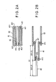
- the arm guide 53 and the main arm 41 are tubular cylinders and the sub-arm 42 is a solid cylinder, where the main arm 41 is accommodated inside the arm guide 53 and the sub-arm 42 is accommodated within the main arm 41 as shown in Figs. 2(A) and (B) .
- the lengths of the arm guide 53, the main arm 41 and the sub-arm 42 are substantially equal in the axial direction thereof.
- a plurality of air bearings 411 are provided along the outer circumference of the main arm 41 on the side of the proximal side (right side in Fig. 2(A) ).
- Another plurality of air bearings 412 are provided along the inner circumference of the distal side of the main arm 41.
- the relative moving mechanism 5 has a column 41 vertically mounted on the horizontal surface of the base 2, a carriage 52 movably supported on the column 51, the arm guide 53 fitted to the carriage 52, and a synchronous driver 54 for moving the main arm 41 and the sub-arm 42 simultaneously in the same direction.
- the length of the carriage 52 in the axial direction is L1, which is longer than the length of the arm guide 53.
- the synchronous driver 54 has a main arm moving mechanism 55 (first moving mechanism) for moving the main arm 41 in the axial direction, and a sub-arm moving mechanism 56 (second moving mechanism) for moving the sub-arm 42 in the same direction as the moving direction of the main arm 41 in synchronization with the main arm moving mechanism 55.
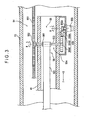
- the main arm moving mechanism 55 has a rack 551 provided on the arm guide 53 along the moving direction of the main arm 41, a pinion 552 rotatably mounted on the main arm 41 to be meshed with the rack 551 and a rotation-applying device 554 for rotating a rotary shaft 553 of the pinion 552.
- the distal end (upper side in Fig. 3 ) of the rotary shaft 553 projects from the main arm 41 and the pinion 552 is attached to the projected tip end.
- the rotation-applying device 554 has a motor 555 and a gear train 556 for transmitting the rotation of the motor 555 to the rotary shaft 553.
- the gear train 556 includes a driving gear 556A attached to a rotary shaft 555A of the motor 555, a transmission gear 556B meshing with the driving gear 556A, and a driven gear 556C attached to the proximal end of the rotary shaft 553 and meshing with the transmission gear 556B.
- the sub-arm moving mechanism 56 has a drive-side pulley 561 fixed approximately at the center of the rotary shaft 553, a driven-side pulley 562 rotatably held near the distal end of the main arm 41, a timing belt 563 wound around the drive-side pulley 561 and the driven-side pulley 562, and a joint 564 provided between the timing belt 563 and the proximal end of the sub-arm 42.
- the diameters of the pinion 552, the drive-side pulley 561 and the driven-side pulley 562 are arranged equal so that the movement amount of the main arm 41 relative to the arm guide 53 (referred to as main arm travel hereinafter) becomes equal to the movement amount of the sub-arm relative to the main arm 41 (referred to as sub-arm travel hereinafter) when the main arm 41 and the sub-arm 42 are moved for a predetermined time by driving the synchronous driver 54.
- the length of the rack 551 and the distance between the drive-side pulley 561 and the driven-side pulley 562 are adjusted so that the stroke of the main arm 41 relative to the arm guide 53 (referred to as main arm stroke hereinafter) becomes equal to the stroke of the sub-arm 42 relative to the main arm 41 (referred to as sub-arm stroke hereinafter) and the sum of the strokes, i.e. the detector stroke becomes S1.
- the carriage 52 is moved along the column 51 in accordance with the height of the measuring point of the workpiece.
- the main arm 41 and the sub-arm 42 are respectively accommodated in the arm guide 53 and the main arm 41 provided as a former component thereof (referred to as initial condition hereinafter).
- the driven gear 556C is also rotated in the R direction.
- the sub-arm 42 is moved in the F direction by the belt-pulley mechanism and the sub-arm travel at the time is detected by a sub-arm position sensor (not shown).
- the detector travel is equal to the sum of the main arm travel and the sub-arm travel, which is calculated by a probe position sensor (not shown).
- the detector travel is equal to the detector stroke S1.
- the dimension of the workpiece can be obtained based on the thus-obtained detector travel when the probe P is in contact with the measuring point.
- the driving gear 556A is rotated in L direction by the motor 555, so that the respective components are rotated and moved in a direction reverse to the above-described direction to return to the initial condition.
- the detector stroke S1 can be arranged as the sum of the strokes of the respective short arms and the lengths of the respective short arms can be made shorter than the detector stroke S1.
- the length of the carriage 52 in which the arm guide 53 for supporting the short arms is fitted can be made shorter than the detector stroke S1, so that a installation space W1 of the measuring instrument 1 can be made smaller than the installation space W7 of the measuring instrument 7, thereby achieving space reduction.
- the detector travel of the measuring instrument 1 is approximately equal to the travel of the arm of the measuring instrument 7 multiplied by the number of the short arms.
- the time for moving the probe P of the measuring instrument 1 for a predetermined distance can be reduced as compared to the measuring instrument 7, so that the time for bringing the probe P into and out of contact to the workpiece can be reduced.
- the arm 4 of the measuring instrument 1 of the present embodiment includes the main arm 41 and the sub-arm 42, the movement time for bringing the probe P into and out of contact with the workpiece can be made approximately half of the movement time of the measuring instrument 7.
- the main arm moving mechanism 55 and the sub-arm moving mechanism 56 are independently provided, the main arm 41 and the sub-arm 42 can be moved at different speeds in accordance with the lengths thereof.
- the main arm moving mechanism 55 and the sub-arm moving mechanism 56 respectively include the inexpensive and simply-structured rack and pinion mechanism and belt-pulley mechanism, the synchronous driver 54 can be inexpensively provided and repair work thereof can be facilitated.
- the two short arms can be driven with a single drive source.
- the plurality of air bearings 411 for movably supporting the main arm 41 relative to the arm guide 53 can be provided along the outer circumference of the proximal end of the main arm 41 and the plurality of air bearings 412 for movably supporting the sub-arm 42 relative to the main arm 41 can be provided along the inner circumference of the distal side of the main arm 41.
- the shift of the main arm 41 and the sub-arm 42 in a direction orthogonal to the moving direction thereof can be restrained, so that measurement error can be restrained.
- the flexure of the main arm 41 and the sub-arm 42 caused when the arm 4 is stretched can be restrained, so that the measurement error can be restrained.
- air bearings 411 and 412 allows smooth movement of the main arm 41 relative to the arm guide 53 and the movement of the sub-arm 42 relative to the main arm 41.
- the arm 4 of the above embodiment includes two short arms, the arm 4 may include more than two arms.
- the diameters of the pinion 552, the drive-side pulley 561 and the driven-side pulley 562 are arranged equal so that the main arm travel is equal to the sub-arm travel when the main arm 41 and the sub-arm 42 arc moved for a predetermined time by driving the synchronous driver 54, the pinion 552, the drive-side pulley 561 and the driven-side pulley 562 may have different diameters so that the main arm travel becomes not equal to the sub-arm travel.
- the length of the rack 551 and the distance between the drive-side pulley 561 and the driven-side pulley 562 are adjusted so that the main arm stroke becomes equal to the sub-arm stroke, the length and the distance may be adjusted so that the main arm stroke becomes different from the sub-arm stroke.
- the installation space W1 can be minimized S1 in the above embodiment.
- the rack and pinion mechanism is provided on the main arm moving mechanism 55 and the belt pulley mechanism is provided on the sub-arm moving mechanism 56 in the above embodiment, other relative moving mechanism may be provided as long as the main arm 41 can be moved relative to the arm guide 53 and the sub-arm 42 can be moved relative to the main arm 41.
- the same advantage can be obtained by simultaneously driving independent drivers respectively for driving the main arm 41 and the sub-arm 42.
- the deformation of the arm 4 can be restrained as compared to an arrangement where only the sub-arm 42 is moved. Further, since only a single arm is moved, the deformation of the arm 4 can be reduced as compared to the arrangement where both of the main arm 41 and the sub-arm 42 are moved. Accordingly the straightness of the movement of the arm 4 can be secured and the measurement accuracy can be improved. On the other hand, when only the sub-arm 42 is moved, narrow section can be measured.
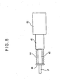
- a probe mount 43 on which a probe P is provided may be attached to the tip end of the sub-arm 42, and a stretchable cover 44 may be attached between the proximal end of the probe mount 43 and the tip end of the main arm 41. According to the above arrangement, the section between the main arm 41 and the sub-arm 42 can be kept clean and the arms can be smoothly moved.
- the stretchable cover may be attached to the outside of the main arm 41, or, alternatively, a single stretchable cover may be attached spanning over the main arm 41 and the sub-arm 42.
- the components may be installed on a one-dimensional or three-dimensional measuring instrument of horizontal or vertical type. For instance, as shown in Fig. 6 , when the above components are installed on a vertical three-dimensional measuring instrument 60, the space in vertical direction can be reduced.
- the probe P is used as the detector, a non-contact detector using a CCD camera or laser beam may be used.
- the present invention can be applied to any measuring instrument as long as the dimension of the workpiece is measured based on a position of a detector.
Landscapes
- Physics & Mathematics (AREA)
- General Physics & Mathematics (AREA)
- A Measuring Device Byusing Mechanical Method (AREA)
- Testing Of Devices, Machine Parts, Or Other Structures Thereof (AREA)
- Length Measuring Devices With Unspecified Measuring Means (AREA)
Claims (7)
- Instrument de mesure (1), comprenant: un bras (4) prévu avec un détecteur (P) à une extrémité distale de celui-ci ; et un support (53) pour supporter le bras (4) d'une manière mobile dans la direction axiale du bras (4),
dans lequel le bras (4) comprend une pluralité de bras courts (41, 42) comprenant un bras court proximal (41) et un bras court distal (42) prévu avec le détecteur (P) à une extrémité distale du bras court distal (42), une extrémité proximale du bras court proximal (41) étant supportée par le support (53) d'une manière mobile par rapport au support (53), le bras court distal (42) étant supporté par une extrémité distale du bras court proximal (41) ou par une extrémité distale d'un des bras courts (42) autre que le bras court proximal (41), les bras courts (42) autres que le bras court proximal (41) étant supportés de manière séquentielle par un bras court précédent parmi les bras courts (41, 42) d'une manière mobile par rapport au bras court précédent parmi les bras courts (41, 42), l'instrument de mesure (1) mesurant une dimension d'une pièce à usiner sur la base de la position du détecteur (P), et
caractérisé en ce que
l'instrument de mesure (1) comporte des éléments d'entraînement (54) pour déplacer de manière sélective et indépendante le bras court proximal (41) et au moins l'un parmi les bras courts (42) dans la direction axiale des bras courts (41, 42) respectifs, les éléments d'entraînement (54) étant des éléments d'entraînement synchrones qui sont reliés mécaniquement et entraînés de manière synchrone. - Instrument de mesure (1) selon la revendication 1, dans lequel le bras court proximal (41) et au moins l'un parmi les bras courts (42) sont entraînés par coopération de formes par les éléments d'entraînement synchrones.
- Instrument de mesure (1) selon la revendication 2, dans lequel l'élément d'entraînement synchrone (54) comporte un premier mécanisme de déplacement (55) pour déplacer le bras court proximal (41) dans la direction axiale et un deuxième mécanisme de déplacement (56) pour déplacer le bras court distal (42)
dans la même direction que la direction de déplacement du bras court proximal (41) en synchronisation avec le premier mécanisme de déplacement (55). - Instrument de mesure (1) selon la revendication 3,
dans lequel le premier mécanisme de déplacement (55) comporte une crémaillère (551) prévue sur le support (53) le long de la direction de déplacement du bras court proximal (41), un pignon (552) prévu de manière rotative sur le bras court proximal (41) et s'engrenant avec la crémaillère (551), et un dispositif d'application de rotation (554) pour faire tourner un arbre (553) du pignon (552), et
dans lequel le deuxième mécanisme de déplacement (56) comporte une première poulie (561) fixée à l'arbre (553) du pignon (552), une deuxième poulie (562) supportée de manière rotative sur l'extrémité distale du bras court proximal (41), et une ceinture (563) enroulée autour des poulies (561, 562), dont une partie étant jointée avec le bras court distal (42). - Instrument de mesure (1) selon la revendication 3 ou 4,
dans lequel le support (53) et le bras court proximal (41) sont des cylindres tubulaires, et
dans lequel le bras court proximal (41) est logé dans le support (53) et le bras court distal (42) est logé dans le bras court proximal (41). - Instrument de mesure (1) selon la revendication 5, comprenant en outre des paliers à air (411, 412) prévus entre le support (53) et le bras court proximal (41) et entre le bras court proximal (41) et le bras court distal (42).
- Instrument de mesure (1) selon l'une quelconque des revendications 3 à 6, comprenant en outre un couvercle (44) qui recouvre le bras court distal (42) depuis l'extrémité distale du bras court proximal (41) jusqu'à l'extrémité distale du bras court distal (42), le couvercle (44) étant étiré et contracté dans la direction de déplacement du bras court distal (42) conformément au mouvement du bras court distal (42).
Applications Claiming Priority (2)
| Application Number | Priority Date | Filing Date | Title |
|---|---|---|---|
| JP2003016048 | 2003-01-24 | ||
| JP2003016048A JP4031375B2 (ja) | 2003-01-24 | 2003-01-24 | 測定機 |
Publications (2)
| Publication Number | Publication Date |
|---|---|
| EP1441194A1 EP1441194A1 (fr) | 2004-07-28 |
| EP1441194B1 true EP1441194B1 (fr) | 2015-09-16 |
Family
ID=32588688
Family Applications (1)
| Application Number | Title | Priority Date | Filing Date |
|---|---|---|---|
| EP04001338.5A Expired - Lifetime EP1441194B1 (fr) | 2003-01-24 | 2004-01-22 | Instrument de mesure |
Country Status (4)
| Country | Link |
|---|---|
| US (1) | US7155364B2 (fr) |
| EP (1) | EP1441194B1 (fr) |
| JP (1) | JP4031375B2 (fr) |
| CN (1) | CN1323275C (fr) |
Families Citing this family (11)
| Publication number | Priority date | Publication date | Assignee | Title |
|---|---|---|---|---|
| WO2010135764A1 (fr) * | 2009-05-25 | 2010-12-02 | Stephen Bruce Alexander | Dispositif de mesure volumétrique |
| JP5286239B2 (ja) * | 2009-12-14 | 2013-09-11 | 株式会社ミツトヨ | 測定子、及び真円度測定機 |
| CN102331247A (zh) * | 2011-08-24 | 2012-01-25 | 青岛德力源五金制品有限公司 | 一种制动杠杆测量设备及测量方法 |
| EP2574412B1 (fr) * | 2011-09-30 | 2014-06-18 | Siemens VAI Metals Technologies GmbH | Capteur de mesure, système de mesure, procédé d'établissement par laser optique de la position en hauteur d'un cylindre de corset de guidage et utilisation du système de mesure |
| CN104880153A (zh) * | 2014-02-28 | 2015-09-02 | 中国科学院寒区旱区环境与工程研究所 | 一种激光传感器测量冻土冻胀位移的装置 |
| KR101611753B1 (ko) * | 2014-11-26 | 2016-04-27 | 주식회사 포스코 | 간격 측정유닛 및 이를 포함하는 압연롤장치 |
| CN104655066A (zh) * | 2015-02-05 | 2015-05-27 | 柳州如洋精密科技有限公司 | 关节臂测量机 |
| CN111024157B (zh) * | 2019-12-20 | 2021-07-06 | 东南大学 | 一种检验水下运动平台的方法 |
| CN113959406B (zh) * | 2021-09-25 | 2023-08-25 | 明达海洋工程有限公司 | 一种矿山地质灾害监测预警装置 |
| CN114136283B (zh) * | 2021-11-16 | 2024-03-29 | 安徽恒信建设工程管理有限公司 | 一种建筑工程测量器 |
| CN114777735B (zh) * | 2022-04-01 | 2025-06-10 | 通州建总集团有限公司 | 一种便于移动的建筑工程垂直度检测装置 |
Citations (1)
| Publication number | Priority date | Publication date | Assignee | Title |
|---|---|---|---|---|
| US6272766B1 (en) * | 1997-10-27 | 2001-08-14 | Johannes Heidenhain Gmbh | Length measuring instrument, and machine having a length measuring instrument |
Family Cites Families (12)
| Publication number | Priority date | Publication date | Assignee | Title |
|---|---|---|---|---|
| US887994A (en) * | 1907-09-18 | 1908-05-19 | Walker B Bartram | Coin-controlled machine for measuring the heights of persons. |
| US3658429A (en) * | 1970-05-11 | 1972-04-25 | Bendix Corp | Displacement measuring apparatus |
| DE2413335C2 (de) * | 1974-03-20 | 1983-11-24 | Mauser-Werke Oberndorf Gmbh, 7238 Oberndorf | Meßmaschine mit zwei Portalen für Werkstücke kleinerer und mittlerer Abmessungen |
| US3940982A (en) * | 1974-09-16 | 1976-03-02 | The United States Of America As Represented By The Secretary Of The Navy | Subbottom rock mapping probe |
| US4432141A (en) * | 1983-06-03 | 1984-02-21 | Marcyan Stanley T | High precision height comparator apparatus |
| DE3514309A1 (de) | 1985-04-19 | 1986-10-23 | Bayerische Motoren Werke AG, 8000 München | Drei-koordinaten-wegaufnehmer |
| US4702009A (en) * | 1986-04-07 | 1987-10-27 | The Dow Chemical Company | Device for measuring the level of a material stored in a tank |
| US4989884A (en) * | 1989-03-13 | 1991-02-05 | Goodman Clarence R | Automotive boot |
| JPH0445911A (ja) | 1990-06-13 | 1992-02-14 | Seiko Instr Inc | ゲート切断の方法および射出成形金型 |
| DE4327250C5 (de) * | 1992-09-25 | 2008-11-20 | Carl Zeiss Industrielle Messtechnik Gmbh | Verfahren zur Koordinatenmessung an Werkstücken |
| DE4238139C2 (de) * | 1992-11-12 | 2002-10-24 | Zeiss Carl | Koordinatenmeßgerät |
| GB0114360D0 (en) * | 2001-06-13 | 2001-08-08 | Renishaw Plc | Stylus orientation |
-
2003
- 2003-01-24 JP JP2003016048A patent/JP4031375B2/ja not_active Expired - Fee Related
-
2004
- 2004-01-20 CN CNB200410039023XA patent/CN1323275C/zh not_active Expired - Fee Related
- 2004-01-20 US US10/759,011 patent/US7155364B2/en not_active Expired - Lifetime
- 2004-01-22 EP EP04001338.5A patent/EP1441194B1/fr not_active Expired - Lifetime
Patent Citations (1)
| Publication number | Priority date | Publication date | Assignee | Title |
|---|---|---|---|---|
| US6272766B1 (en) * | 1997-10-27 | 2001-08-14 | Johannes Heidenhain Gmbh | Length measuring instrument, and machine having a length measuring instrument |
Also Published As
| Publication number | Publication date |
|---|---|
| CN1323275C (zh) | 2007-06-27 |
| US7155364B2 (en) | 2006-12-26 |
| US20040148126A1 (en) | 2004-07-29 |
| JP2004226298A (ja) | 2004-08-12 |
| CN1517675A (zh) | 2004-08-04 |
| JP4031375B2 (ja) | 2008-01-09 |
| EP1441194A1 (fr) | 2004-07-28 |
Similar Documents
| Publication | Publication Date | Title |
|---|---|---|
| US7155364B2 (en) | Measuring instrument | |
| KR20200011145A (ko) | 기어 검사장치 및 이를 이용한 기어 검사방법 | |
| EP0553763A1 (fr) | Méthode et appareil pour mesurer l'épaisseur de dent d'engrenage | |
| US7168855B2 (en) | X-ray stand | |
| JP2001027583A (ja) | バックラッシ測定装置 | |
| JPH07100781A (ja) | 多関節型ロボット | |
| CN119289830B (zh) | 一种内齿跨距测量装置 | |
| KR970006926Y1 (ko) | 음극선관의 화면특성 측정 수단의 이송장치 | |
| JP2002021964A (ja) | 直線移動装置 | |
| JP2000288853A (ja) | ハイブリッド型多自由度機構 | |
| JP3224987B2 (ja) | 超音波探傷装置 | |
| JP2001004320A (ja) | 駆動列のバックラッシュを測定する方法および装置 | |
| CN216049686U (zh) | 一种用于核燃料包壳管或燃料棒的长度和外径测量装置 | |
| CN110470735A (zh) | 一种管件的paut实验装置 | |
| CN216645278U (zh) | 一种适用于三坐标检测用的辅助装置 | |
| JPH028714Y2 (fr) | ||
| JP2004130437A (ja) | テレスコピックカバー装置 | |
| JP2010223725A (ja) | 光学式エンコーダ及び線状動力伝達部材の変位検出方法 | |
| JPH10118718A (ja) | プレスブレーキ | |
| JP4253940B2 (ja) | 可動式照明装置 | |
| JPH07102508B2 (ja) | 移動機構 | |
| JPS58187809A (ja) | 移動量測定装置 | |
| CN222774278U (zh) | 一种减速机啮合精度检测装置 | |
| JPH04261753A (ja) | 工作機械における作動体の位置決め制御装置 | |
| CN120351871B (zh) | 一种基于大尺寸光学玻璃平面度测量装置 |
Legal Events
| Date | Code | Title | Description |
|---|---|---|---|
| PUAI | Public reference made under article 153(3) epc to a published international application that has entered the european phase |
Free format text: ORIGINAL CODE: 0009012 |
|
| AK | Designated contracting states |
Kind code of ref document: A1 Designated state(s): AT BE BG CH CY CZ DE DK EE ES FI FR GB GR HU IE IT LI LU MC NL PT RO SE SI SK TR |
|
| AX | Request for extension of the european patent |
Extension state: AL LT LV MK |
|
| 17P | Request for examination filed |
Effective date: 20040917 |
|
| AKX | Designation fees paid |
Designated state(s): DE FR GB IT |
|
| 17Q | First examination report despatched |
Effective date: 20101119 |
|
| REG | Reference to a national code |
Ref country code: DE Ref legal event code: R079 Ref document number: 602004047899 Country of ref document: DE Free format text: PREVIOUS MAIN CLASS: G01B0005008000 Ipc: G01B0005004000 |
|
| GRAP | Despatch of communication of intention to grant a patent |
Free format text: ORIGINAL CODE: EPIDOSNIGR1 |
|
| RIC1 | Information provided on ipc code assigned before grant |
Ipc: G01B 5/004 20060101AFI20150416BHEP |
|
| INTG | Intention to grant announced |
Effective date: 20150507 |
|
| RIN1 | Information on inventor provided before grant (corrected) |
Inventor name: MURAOKA, YOSHIKAZU |
|
| GRAS | Grant fee paid |
Free format text: ORIGINAL CODE: EPIDOSNIGR3 |
|
| GRAA | (expected) grant |
Free format text: ORIGINAL CODE: 0009210 |
|
| AK | Designated contracting states |
Kind code of ref document: B1 Designated state(s): DE FR GB IT |
|
| REG | Reference to a national code |
Ref country code: GB Ref legal event code: FG4D |
|
| REG | Reference to a national code |
Ref country code: DE Ref legal event code: R096 Ref document number: 602004047899 Country of ref document: DE |
|
| REG | Reference to a national code |
Ref country code: FR Ref legal event code: PLFP Year of fee payment: 13 |
|
| REG | Reference to a national code |
Ref country code: DE Ref legal event code: R097 Ref document number: 602004047899 Country of ref document: DE |
|
| PLBE | No opposition filed within time limit |
Free format text: ORIGINAL CODE: 0009261 |
|
| STAA | Information on the status of an ep patent application or granted ep patent |
Free format text: STATUS: NO OPPOSITION FILED WITHIN TIME LIMIT |
|
| 26N | No opposition filed |
Effective date: 20160617 |
|
| REG | Reference to a national code |
Ref country code: FR Ref legal event code: PLFP Year of fee payment: 14 |
|
| REG | Reference to a national code |
Ref country code: FR Ref legal event code: PLFP Year of fee payment: 15 |
|
| PGFP | Annual fee paid to national office [announced via postgrant information from national office to epo] |
Ref country code: FR Payment date: 20210121 Year of fee payment: 18 Ref country code: IT Payment date: 20210121 Year of fee payment: 18 |
|
| PGFP | Annual fee paid to national office [announced via postgrant information from national office to epo] |
Ref country code: DE Payment date: 20210120 Year of fee payment: 18 Ref country code: GB Payment date: 20210121 Year of fee payment: 18 |
|
| REG | Reference to a national code |
Ref country code: DE Ref legal event code: R119 Ref document number: 602004047899 Country of ref document: DE |
|
| GBPC | Gb: european patent ceased through non-payment of renewal fee |
Effective date: 20220122 |
|
| PG25 | Lapsed in a contracting state [announced via postgrant information from national office to epo] |
Ref country code: GB Free format text: LAPSE BECAUSE OF NON-PAYMENT OF DUE FEES Effective date: 20220122 Ref country code: DE Free format text: LAPSE BECAUSE OF NON-PAYMENT OF DUE FEES Effective date: 20220802 |
|
| PG25 | Lapsed in a contracting state [announced via postgrant information from national office to epo] |
Ref country code: FR Free format text: LAPSE BECAUSE OF NON-PAYMENT OF DUE FEES Effective date: 20220131 |
|
| PG25 | Lapsed in a contracting state [announced via postgrant information from national office to epo] |
Ref country code: IT Free format text: LAPSE BECAUSE OF NON-PAYMENT OF DUE FEES Effective date: 20220122 |